Building a Key Programming & ECU
Immobiliser Testing Interface
Following on from the write-ups I have done recently on
· Decoding & Cloning The Lucas 5AS Immobiliser Part 1 Part 2
· Building a Crank & Cam Simulator
… I built an interface which allowed me to run an ECU, Immobiliser & Key Programmer (or OBDII scanner) (using a standard OBDII diagnostic socket) and optionally my Crank & Cam Simulator together on the bench.
After rebuilding a number of ECUs, immobilisers and key fobs I wanted to be able to code them together in sets. I also get asked quite frequently by club members to help with coding ECUs and immobilisers, or immobilisers and key fobs, or with the supply of replacement key fobs. I used to have a full engine testbed running on a test trolley and tended to use this for this kind of work, but having decided that it was a waste of a very good engine, and having served its purpose as a learning exercise I sold this engine and didn’t want to keep connecting and disconnecting components on my car. So I decided to put together a simple minimal interface to allow me to do this work on the bench.
There were two levels I could take this to; the simplest interface would allow me to run an ECU, Immobiliser & Key Programmer (or OBDII scanner) and a more advanced interface would allow me to include the Crank & Cam Simulator. Unfortunately I have found that sometimes when coding an ECU to match an immobiliser using my T300+ clone key programmer, the ECU reports that it has completed the operation when it has not succeeded and the ECU remains immobilised. It is therefore necessary to have some way of testing to see whether an ECU is immobilised or not, and for this reason, in order to allow full testing, I decided from the start to include the Crank & Cam Simulator and build the advanced interface, but I have documented below the requirements for the simple interface too in case anyone wants to build one and doesn’t want to go to the lengths of building a Crank & Cam Simulator too.
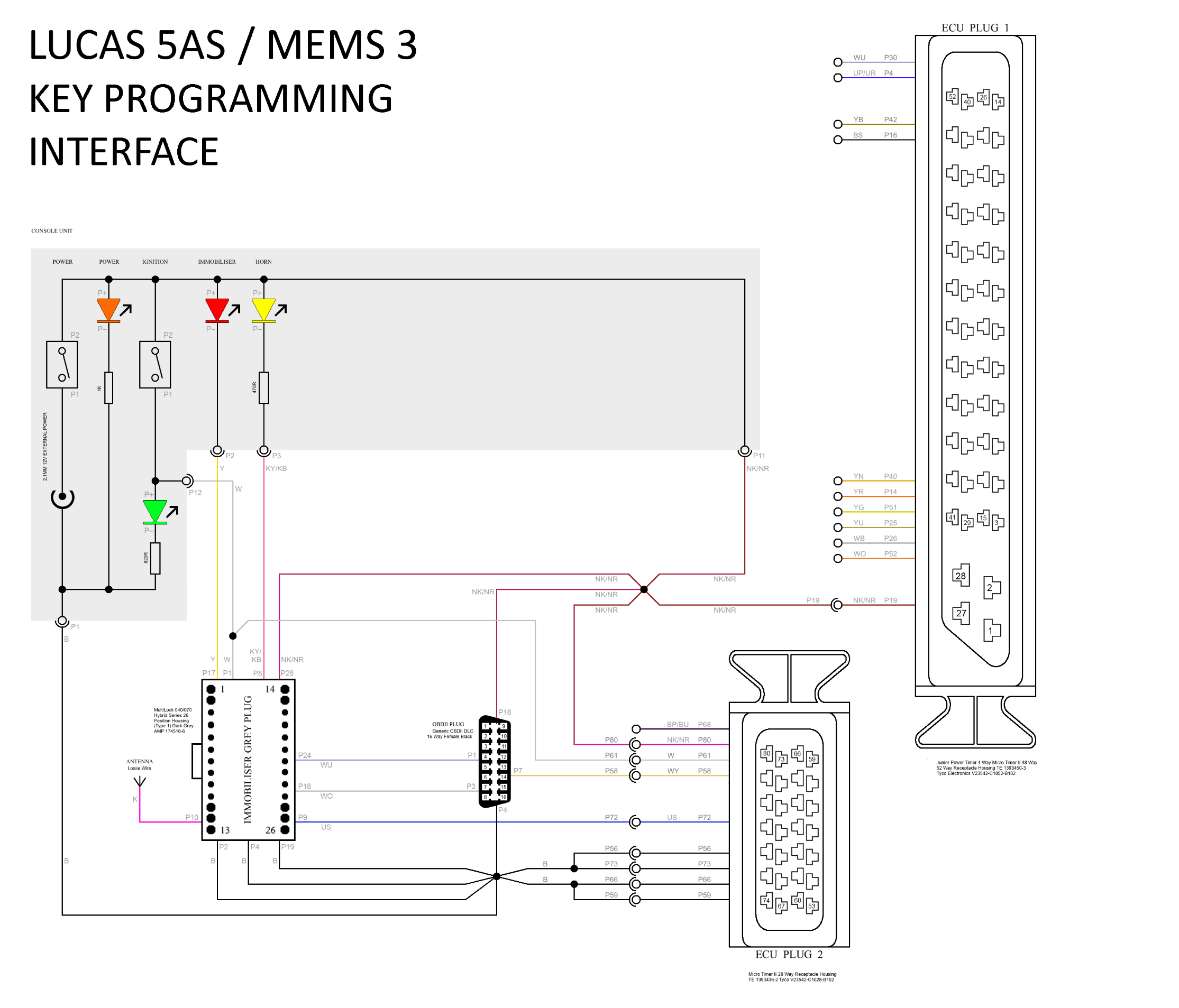
The simple interface circuit diagram is shown below.
The box shaded in grey is intended to be constructed in a box as a console unit to control the whole setup. This has a 12V DC supply socket, two switches and LEDs to indicate when they are on - one to power the whole interface on and off (simulates connecting the battery on the car - the key programmer works most reliably when the ECU and immobiliser are powered up clean, so I wanted to be able to reset them by powering off) and one to function as the ignition switch, plus LEDs for the immobiliser (representing the red flashing LED normally on the dash) and the horn (the immobiliser signals when it has accepted a key during programming by sounding the horn, or in this system by flashing the horn LED). Note that the different colour LEDs require different values of series resistors to operate at a sensible brightness on 12V as they have different forward voltages, and the immobiliser LED does not require a series resistor at all as this is already built into the immobiliser itself.
NB: Even with the
resistor values shown, the LEDs on my finished interface are very bright,
possibly rather too bright for comfortable viewing. Higher value resistors may
be more appropriate to limit the current and brightness but I didn’t go back to
experiment with lower values and left the resistors as shown on mine.
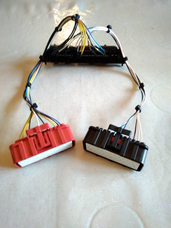
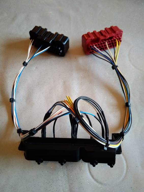
The rest of the system is constructed as a free standing wiring loom. As there are no significant currents in test system I used 0.5mm² cable throughout as this kept the whole loom as flexible as possible, which made it a lot more convenient on the bench (some of the terminals used such as the Multilock .040 terminals in the immobiliser plug are designed to take 0.5mm² or smaller cables). The wire colours I used are shown in the diagram below and these largely follow the colours of the same wires in the looms on the car. Some of the wire colours are hard to find in 0.5mm² cable and a lot of places only stock the full range in 1mm² upwards. I ordered my cable from http://shop.kabelknecht.de/ and was very happy with the quality. The insulation is rugged but flexible and the colour marking used is very clear. Whilst they stocked most of the colours, there were still some which were not available. Where two colours are shown in the diagram below (e.g. NK/NR - Brown Pink / Brown Red), the first colour (e.g. NK - Brown Pink) is the ideal colour according to the car loom convention and the second colour is the actual colour used in this project (e.g. NR - Brown Red) which is usually as close as I could get.
The wiring loom includes the following connections:
· Permanent and ignition switched power supplies and grounds for the ECU, immobiliser and OBDII socket.
· A free wire antenna for the immobiliser (just around 30cm of pink wire hanging freely away from the loom).
· Immobiliser and horn LED connections from the immobiliser.
· Diagnostic communication connections between the immobiliser and ECU and the OBDII socket.
· Coded signal from the immobiliser to the ECU.
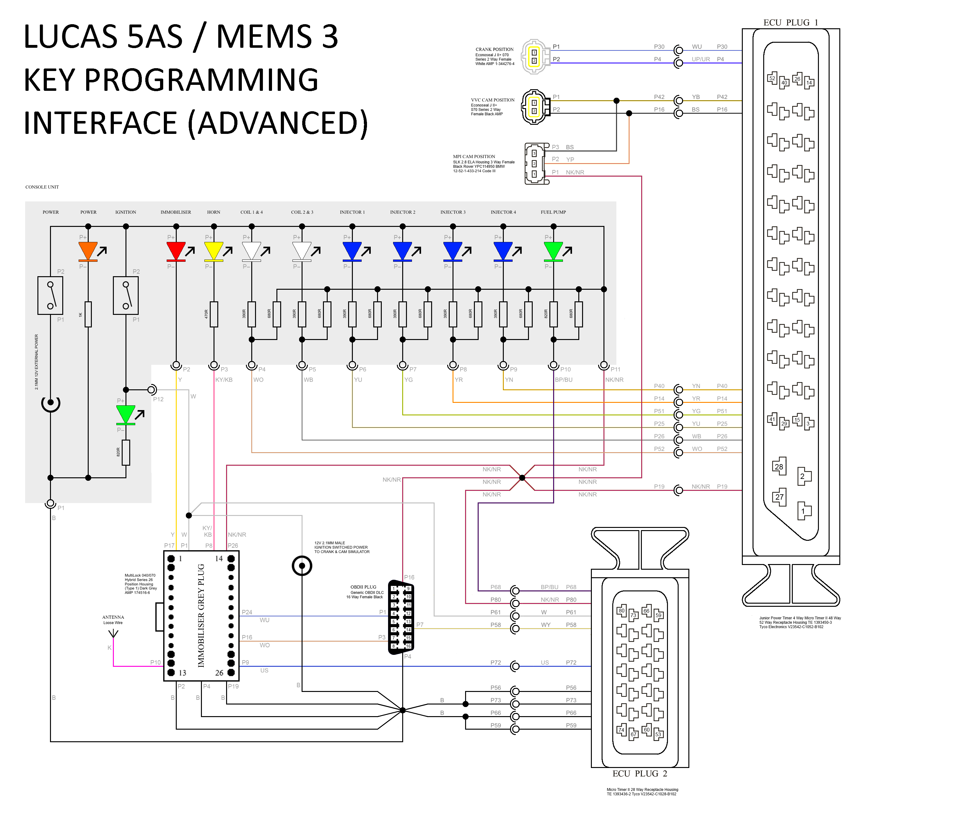
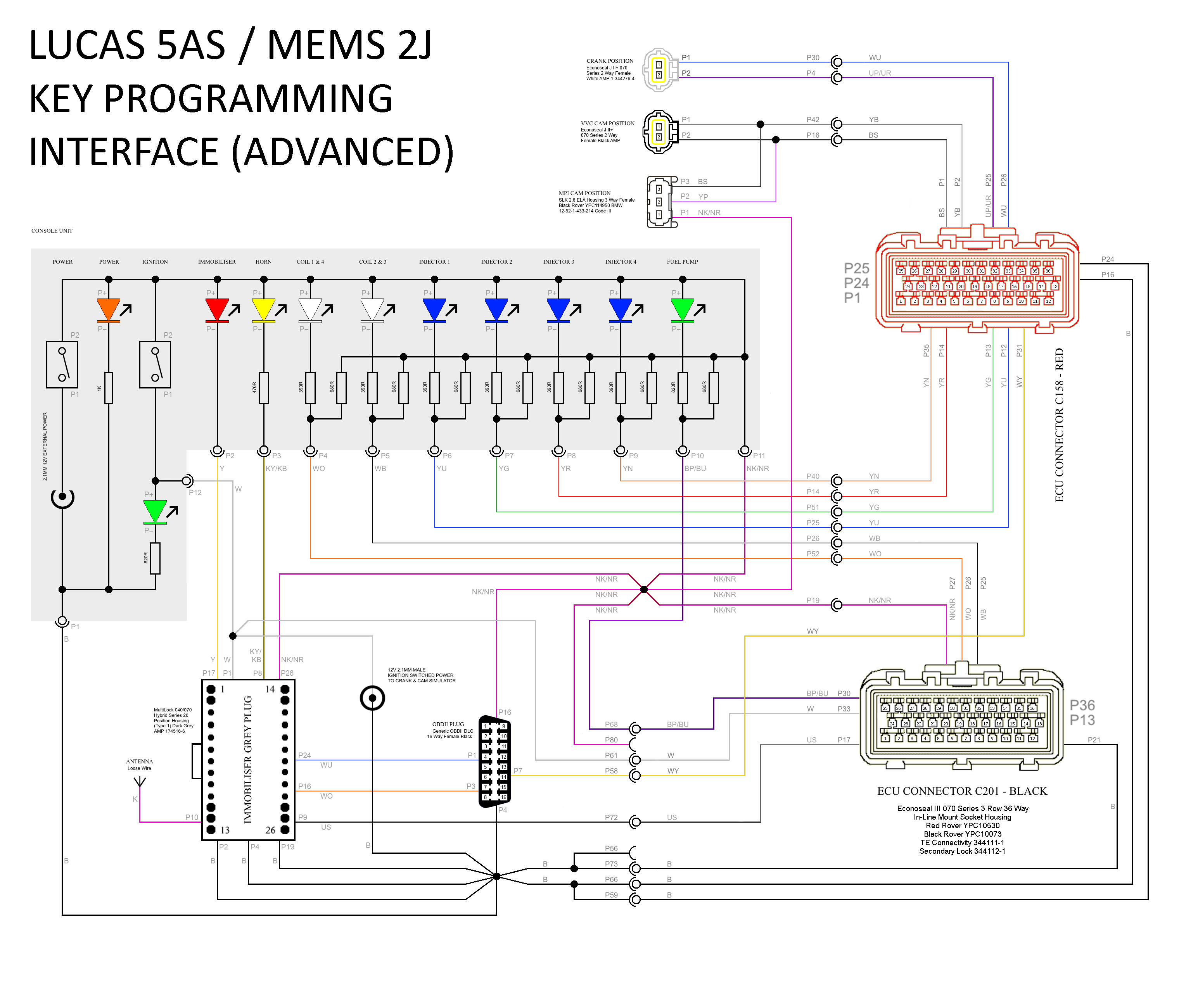
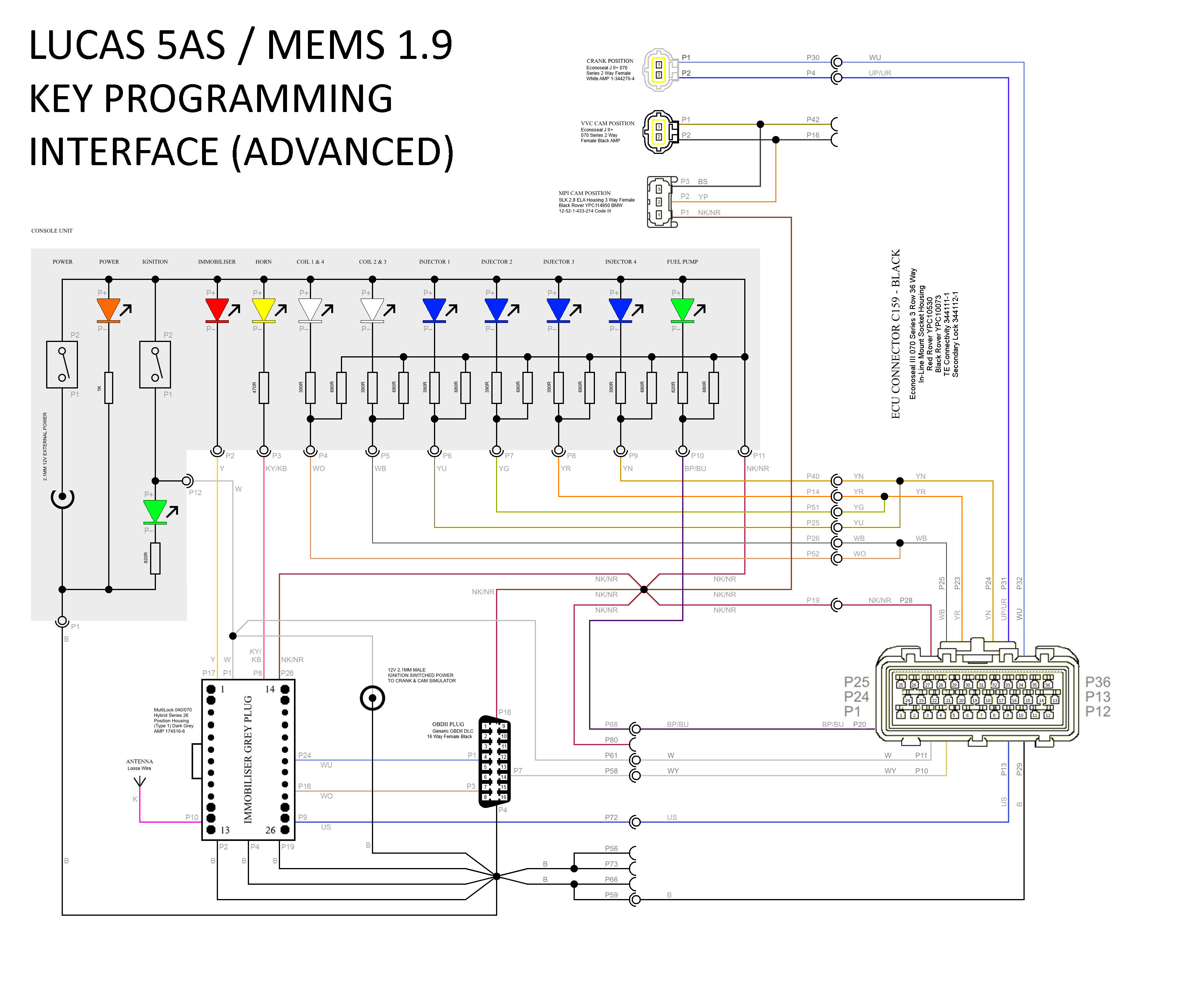
The advanced interface circuit diagram is shown below.
This contains everything included in the basic interface described above and is constructed in exactly the same way, but adds the following:
· LEDs in the console to indicate the operation of the ECU ignition coil drive outputs.
· LEDs in the console to indicate the operation of the ECU fuel injector outputs (for confirming the immobilisation status).
· LED in the console to indicate when the ECU has turned the fuel pump on.
· All of the wiring for the above from the ECU connectors.
· Connectors for the crank position sensor and cam position sensor (both VVC and non-VVC) and appropriate wiring to the ECU connector (in order to allow the Crank & Cam Simulator to be connected - NB: Only connect one of the cam position sensor connectors depending on the ECU being tested as they both use the same ECU pins but for incompatible signals and connecting both will give a mixed signal unreadable by either type of ECU).
Note that as well as series resistors, the LEDs for the ignition and injection outputs have low value pull-up resistors to the +12V supply rail. The ECU outputs which drive these are transistor switched which saturate to ground when turned on. These are high current outputs designed to switch around 1A in the case of the injectors and 10A in the case of the ignition coil packs. Without the pull-up resistors, leakage through the ECU drivers allows enough current to pass to light the LEDs fairly brightly even when turned off (only a couple of milliamps is required), making it very hard to distinguish between the on and off states. The pull-up resistors fix this by requiring a minimum current before the forward voltage of the LEDs is reached, giving a much clearer on/off action. Suitable values for all of the resistors are shown in the diagram, which again very according to the colours of the LEDs.
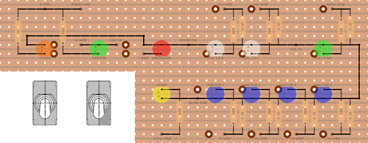
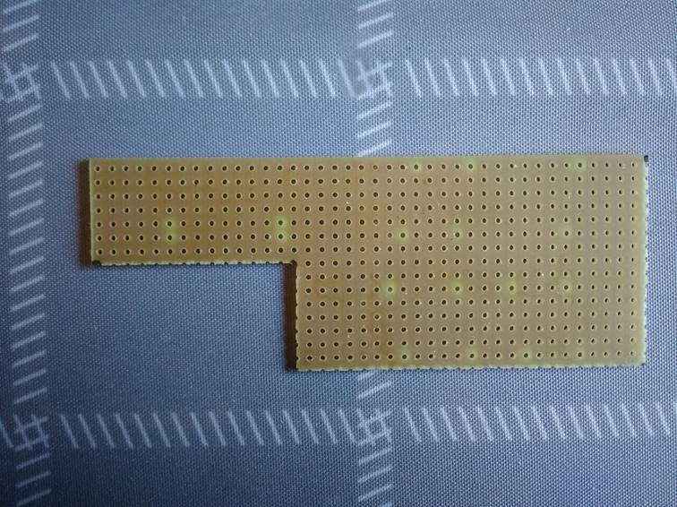
The console unit was constructed using stripboard and housed in a small plastic enclosure. My design for the circuit board is as shown below. If you want to construct the simple version of this interface, simply omit the seven addition LEDs on the right hand side and their corresponding resistors and wire connections. If anyone wants the original files for the plans and designs, including the circuit board which is a multi-layer Paint.NET project, I have everything saved and I’m more than happy to share.
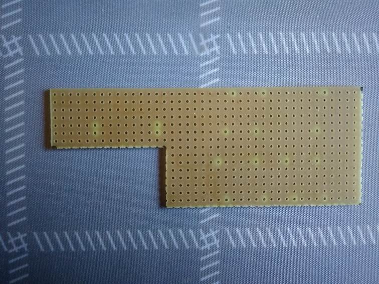
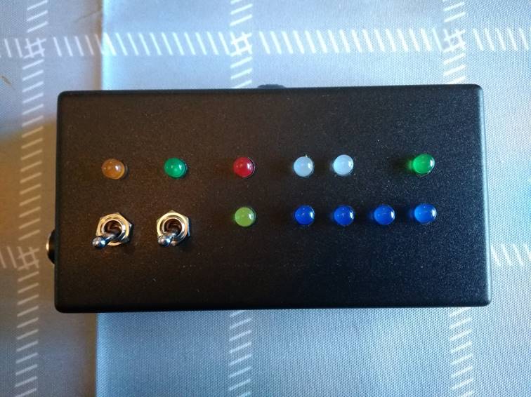
Here are some photographs of the completed console unit.
Bare stripboard, front view:
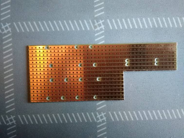
Bare stripboard, reverse view:
Completed console, front view:
Completed console, reverse view:
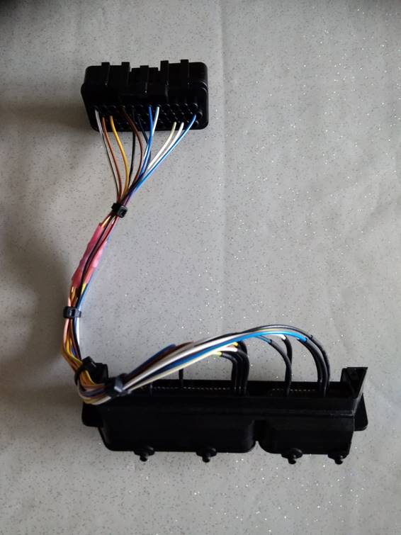
As originally conceived, the interface was targeted only at EU3 (MEMS 3) ECUs, however I have since had several requests for help with EU2 ECUs, both VVC (MEMS 2J) and non-VVC (MEM 1.9). Both of these ECUs can be programmed with this interface either by fitting the appropriate ECU connector(s) in place of the EU3 connector, or by making up EU3 to EU2 adapters. In my case, as I had already constructed the loom and didn’t want to start cutting and modifying, I went down the route of making adapters. I used the connectors removed from a couple of old EU3 ECUs, cut off the unused pins at the rear and soldered wires to the used pins, which were then wired onto appropriate 36-way Econoseal connectors for the EU2 ECUs.
In the case of MEMS 2J, one of the earths and the permanent power supply are not required. In the case of MEMS 1.9, only one earth is required and the injectors and coils are connected in parallel in pairs (as there is no cam sensor and a single coil with distributor).
All of the different ECUs behave very similarly whilst programming. With any of the ECUs, you use the key programmer exactly as though it was plugged into the diagnostic socket on the vehicle. I won’t describe the full programming procedure here as it varies from one programmer to another and the programmers are generally fairly simple and intuitive to use and come with instructions. Start by switching on the power switch on the interface which will also power up the programmer, then follow the usual procedure for the programmer using the ignition switch on the interface when required to turn the ignition on and off as instructed.
The 5AS immobiliser will flash the yellow horn LED once after each key is programmed to acknowledge that programming is complete.
After programming, the immobilisation status of the ECU can be tested by turning the power and ignition on and then switching on the Crank & Cam Simulator to simulate the engine being started, and watching whether the ECU continues to run the engine by observing the coil and injector LEDs and the fuel pump LED. If the ECU is correctly coded to the immobiliser, it will behave as it would on the car, allowing the engine LEDs to run when the immobiliser is disarmed and shutting it down when the immobiliser is armed. If not, the engine LEDs won’t run at all.
A little bit of experimentation also settles once and for all an argument that I’ve had with several people over the years: THE IMMOBILISER DOES NOT DISABLE THE FUEL PUMP! Common wisdom on the Internet has it that when immobilised, the ECU shuts down the fuel pump which kills the engine. This would be far too easy to bypass (I always wonder whether any of the people who keep putting forward this theory have ever tried jumping 12V into the inertia switch connector to force the pump to run to see whether the engine would then run - I can assure you it wouldn’t!). What actually happens is that the ECU shuts down the injectors, leaving the coils firing. You can see this clearly on the test interface as the blue LEDs stop flashing but the white LEDs continue to run normally. Obviously with the injectors shut down, the engine comes to a standstill and the crank sensor signal then stops. The ECU runs the fuel pump purely in response to a crank sensor signal; it doesn’t have to be a clean signal or one that it can synchronise with, anything with occasional zero voltage crossings is enough to get the ECU to run the pump. So when the crank sensor signal stops, the ECU shuts down the fuel pump a fraction of a second later. When running on this interface, even after immobiliser causes the ECU to shut the injectors down, the fuel pump LED remains lit for as long as a crank sensor signal is applied. So the pump stops because the engine stopped, not the other way around. On my car I have an inline fuel pressure gauge in the high pressure hose, and when the engine stops because of the immobiliser the fuel rail is left full pressurised rather than exhausted.