Decoding
& Cloning The Lucas 5AS Immobiliser -
Part 2
So you get what you paid for, and my Chinese clone XPROG-M programmer died. It was never very healthy, there was clearly a dry joint or bad connection somewhere on the board that made it work intermittently but I failed to find it and it eventually packed up completely. OK, I’ll be honest, I tried to reflow solder it to fix the problem and fried it! So I had to order another one and had a bit of a battle with UK customs which involved it being returned to China twice, but eventually it arrived and I was back in business. This one seemed a lot more reliable.
In the meantime I wasn’t twiddling my thumbs on this project though.
Firstly, I set up a test mule 5AS immobiliser. As several people correctly pointed out, repeatedly soldering and desoldering the microcontroller was not a practical solution when it came to tracking down the configurable properties in the EEPROM data. I was going to have to try out many different configurations to work out what some of the settings did (I would thing I’ve actually reprogrammed it several hundred times in total now). One alternative was to try to crack the communications protocol which is used to configure the unit. This however had three drawbacks:
· I didn’t know where to start. If I had a tool that could program the 5AS I would at least have some communications to look at and attempt to decode, but I didn’t - and if I did, I wouldn’t need to crack the communications protocol anyway!
· I would then be limited to changing only those parameters supported by the protocol. Whilst this would have helped me in providing some guidance as to what was possible, it may also have limited me and prevented me from playing with things that were never really intended to be configurable.
· If I “bricked” an immobiliser by applying settings which prevented it from operating normally, I may not then be able to communicate with it to put things back as they were to recover it.
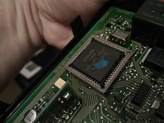
So instead I opted to remove the microcontroller chip and replace it with a socket that would allow me to just plug the chips in and out without soldering. This turned out to work really well. Once I’d got into practice, I could shut my test system down, unplug the chip and plug it into my programmer, load a new configuration and then return the chip to the immobiliser and power it back up in about 20 seconds, so it really took all of the pain out of the cycle.
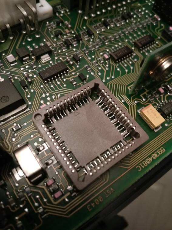
Learning the best way to solder the socket in took a little time, but once I’d got it cracked it was straightforward so I went ahead and soldered sockets into all of my spare immobilisers, making them all easily programmable now. I would normally use 350°C hot air for desoldering the microcontroller quickly to avoid damage but using anything like that just melted the plastic socket. In the end I worked out that anything less than 200°C would not get the solder paste to melt and flow properly but anything more than 200°C damaged the socket; 200°C exactly though was spot on, it needed slow and careful working to make sure that all of the solder paste had fully fused on all of the connections but it really didn’t impact on the plastic socket at all so I could take my time.
Secondly, I used the time to develop the software utility I wrote earlier into to a fully configurable 5AS editor and hacking tool.
You can download a copy of this tool here: https://andrewrevill.co.uk/Downloads/Edit5AS.zip. You need to download the ZIP file and unzip all files into a single folder. To run the application, double click the "Edit5AS.exe" file.
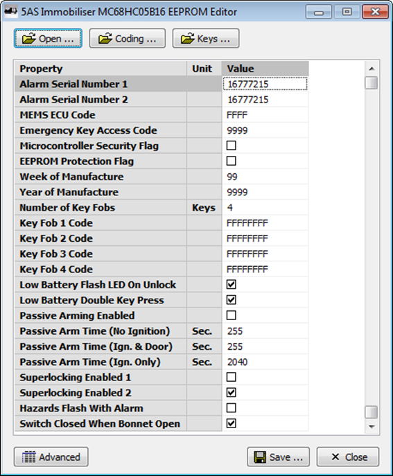
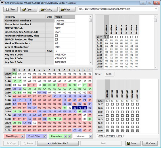
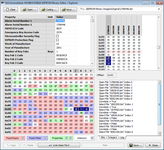
In basic mode, it now acts as proper editor for setting the properties of an immobiliser. It lets you open one BIN file, downloaded from the microcontroller EEPROM, and update the various properties. The properties are defined using an external text file so additional properties can be added as found without recompiling the tool, unless they behave in some way not seen previously. Each property is edited in the appropriate format (e.g. binary, binary coded decimal, decimal or Boolean check box) and validated according to defined minimum and maximum values, allowed digits etc.
In advanced mode it allows me to open up multiple files at once and compare them. It highlights the areas for the storage of properties defined in the text file described above (in green, with a dark blue highlight showing the current property when you click into the editor grid). It also highlights in red any areas which are always 00 or FF in all of the open files (and are probably unused) and in blue any areas which hold other fixed values across all files (and probably correspond to common settings). White areas hold variable data which gives me a clue where to look when I have properties which vary between immobilisers. It allows me to edit property values as above, or to directly manipulate individual bytes and even single bits. I can edit anything anywhere in any grid and the others update to reflect the changes.
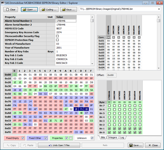
In addition I built in a number of tools to make it easier to hunt down correlations of data with known features. In the top right hand grid in the picture below I have set correlation flags for the superlocking feature. From testing, I knew that the first two immobilisers had superlocking enabled and the others didn’t (each flag can be set to “True”, “False” or “Don’t Care” where it is not known whether a certain feature is present in a given immobiliser or where I want to exclude one form the comparison for one reason or another).
The scrolling down, you can see it immediately highlights the byte at offset 0x35 as being strongly correlated (you can see below that bit 6, highlighted in red, could possibly be controlling superlocking if a 0 turns it on, and bits 4 and 3, highlighted in blue, could possibly be controlling superlocking if a 1 turns it on). The byte at offset 0x36 was also highlighted as being somewhat correlated, with one single bit matching the pattern set.
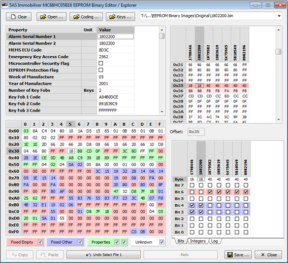
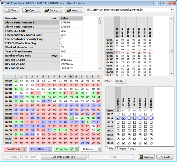
The only other byte that it highlighted was at offset 0x9A, where bit 6 appeared to be correlated. This immediately narrowed down my search to 5 bits across 3 bytes and made it very easy to try toggling these bits to see what effect they had. In this case it turned out that the two single bits at offsets 0x36 and 0x9A together controlled superlocking.
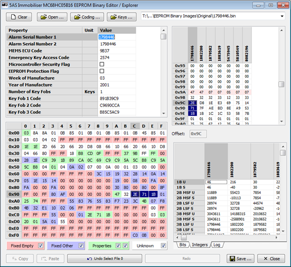
I also added a feature to decode the data at the current address as 1, 2, 3 and 4 byte integers in both most significant byte first and least significant byte format, both signed and unsigned. This turned out not to be so useful though as the only multi-byte integer I found was the serial number. Here you can see the serial number 1798446 decimal appearing as a 3 byte, least significant byte first, unsigned integer (row “3B LSF U”). In other cases, where integer numbers larger than 255 were needed (such as to set a 600 second passive arming time delay), a lower resolution was used (in this case the time delay is specified as a multiple of 8 seconds).
I also added a complete history log with full undo and redo functionality, which made it a lot easier to keep track of the changes I was making and what was affecting what.
So what did I manage to find using all of this?
Well my motivation for a lot of this is a project I have planned, which I will eventually write up separately, in which I want to enable the alarm functionality of the 5AS on my car. In order to do this and to make it work the way I want I need to be able to adjust certain settings, so I had a list of settings I really needed to find. I think I’ve found all of those, plus a few others. To be honest I think I’ve found most of the settings I’m aware of that might be at all interesting or useful in a Caterham installation (and some which are of no use at all).
I’ve listed below the properties which I’ve found so far. There’s a sneak preview summary of the list in the first picture of my software editor earlier in this post, but below I’ve listed the identified properties in full, with their display and editing formats, offsets in the EEPROM, length in bytes, LSB or MSB arrangement where the length is greater than 1, active levels for bit flags and useful notes as appropriate.
There’s still a lot of data in the EEPROM that I haven’t decoded. A lot of this will turn out not to be configuration settings. I know for sure that the alarm records a certain amount of logging information about the last 5 events that triggered it and this will account for some of the bytes. There is also quite a bit of what I might call “dynamic configuration” data which will change at run time, such as rolling key states and other information used to maintain synchronisation with the key fobs, counts of the number of low battery transmissions received form each key fob etc. There is also information recording the current state of the immobiliser and alarm as all of this is preserved when the unit is powered off.
So far I’ve done quite a bit of probing of the areas highlighted in blue in the screenshots above, i.e. areas which hold values other than 00 or FF and which have the same values in all immobilisers I have seen, looking for behaviours which are the same across all the immobilisers I have but still configurable. I have tried setting blocks of these bytes to 00 and to FF to toggle all of the bits to see if I can trigger any strange behaviours to investigate but so far I haven’t turned up anything particularly useful. I seem to have managed to put it into an engineering test mode where it was reporting sensor states on the security LED. I also found a way of cleaning up the outputs by turning off the locking motor drive, but it seemed to disable the security LED so wasn’t particularly helpful; I think it was more a malfunction than a feature.
I haven’t yet played much with the areas in red, which are always 00 or FF. My first working assumption was that these were unused areas, but especially where they appear as single bytes they are equally likely to be bit flags which are always set one particular way as standard, or values which just happen to be 0 or 256, so there will probably be more to come when I get the time to play more, but I think I’ve got most of the important stuff already.
For now, when program an immobiliser I’ll just leave all other unknown areas alone - or more likely, I’ll use one immobiliser which I know is working just as I want it to for my project as a template, only update those areas I understand and then import the coding data from other immobilisers to make up new files for them.
So here’s the full list so far:
Alarm Serial Number 1 (This Alarm)
Decimal Integer
Offset 0x9C
Length 3
LSB First
Repeated at Offset 0xC7
This is the serial
number printed on the label on the front of the case. For some unknown reason
it always appears twice in the EEPROM data at offsets 0x9C and 0xC7. The two
copies are always identical. I believe this to be informational only. I don’t
believe it affect functionality in any way.
For modified 5AS units
which have been upgraded with a template taken from another, I have decided to
use the field at offset 0x9C to store the actual serial number for the current
unit and the field at offset 0xC7 to store the serial number of the unit from
which the template was taken.
Alarm Serial Number 2 (Template Used)
Decimal Integer
Offset 0xC7
Length 3
LSB First
Repeated at Offset 0x9C
This is the serial
number printed on the label on the front of the case. For some unknown reason
it always appears twice in the EEPROM data at offsets 0x9C and 0xC7. The two
copies are always identical. I believe this to be informational only. I don’t
believe it affect functionality in any way.
For modified 5AS units
which have been upgraded with a template taken from another, I have decided to
use the field at offset 0x9C to store the actual serial number for the current
unit and the field at offset 0xC7 to store the serial number of the unit from
which the template was taken.
MEMS ECU Code
Hexadecimal Integer
Offset 0x3B
Length 2
LSB First
This is the unique
immobiliser identity code sent to the MEMS ECU. All values other than 0x0000,
0xFFFF and 0xF0F0 are permitted.
Emergency Key Access Code
Hexadecimal Integer
Offset 0xA0
Length 2
MSB First
BCD, MSD First
This is the code which
can be entered using the driver’s door key to disable the alarm and immobiliser
if the key is lost or inoperative.
Microcontroller Security Flag
Boolean Flag
Offset 0x00
Bit 0
Active Low
This is a feature
implemented in the hardware of the microcontroller. When set to 0, this bit is
designed to prevent the microcontroller being placed into non-user mode and
prevents access to the memory contents by external programmers. Some
programmers such as the XPROG-M claim to be able to circumvent this with
glitching attacks. In the standard 5AS this bit is inactive (set to 1) and the
microcontroller is therefore open.
NB: In my 5AS editor I
added a confirmation prompt when changing this property as if set to 0, it may
no longer be possible to program the microcontroller again.
EEPROM Protection Flag
Boolean Flag
Offset 0x00
Bit 1
Active Low
This is a feature
implemented in the hardware of the microcontroller. When set to 0, this bit
prevents write access to an area of the EEPROM to protect it against accidental
overwriting. In the standard 5AS this bit is inactive (set to 1) and the EEPROM
is therefore unprotected.
NB: In my 5AS editor I
added a confirmation prompt when changing this property as if set to 0 it may
prevent the normal operation of the immobiliser.
Week of Manufacture
Hexadecimal Integer
Offset 0xCF
Length 1
BCD (0-9 Only), MSD First
This is the week
number printed on the label on the front of the case. I believe this to be informational only. I don’t believe it affect
functionality in any way.
Year of Manufacture
Hexadecimal Integer
Offset 0xD0
Length 2
MSB First
BCD (0-9 Only), MSD First
This is the year
number printed on the label on the front of the case. I believe this to be informational only. I don’t believe it affect
functionality in any way.
Number of Key Fobs
Decimal Integer
Offset 0x53
Length 1
1-4
This is the number of
key fobs that the 5AS is programmed to recognise. There are slots for four key
codes in the EEPROM, so up to four keys may be programmed. The codes for the N
programmed keys appear in the first N slots, the others are ignored.
Key Fob 1 Code
Hexadecimal Integer
Offset 0x42
Length 4
LSB First
This is the unique key
code for the first key fob programmed.
Key Fob 2 Code
Hexadecimal Integer
Offset 0x46
Length 4
LSB First
This is the unique key
code for the second key fob programmed.
Key Fob 3 Code
Hexadecimal Integer
Offset 0x4A
Length 4
LSB First
This is the unique key
code for the third key fob programmed.
Key Fob 4 Code
Hexadecimal Integer
Offset 0x4E
Length 4
LSB First
This is the unique key
code for the fourth key fob programmed.
LED Pattern Mask (Armed)
Hexadecimal Integer
Offset 0x90
Length 1
This byte determines
the LED flash pattern when the immobiliser is armed. The pattern encoding can
generate a range of LED flash patterns with one or multiple flashes per cycle
as well as permanently on or off. Some example flash patterns are listed below:
·
0x00
$00000000 Permanently Off (Default Disarmed Pattern)
·
0xFF
$11111111 On for 8ms, Off for 1016ms (Default Armed Pattern)
·
0xFE
$11111110 On for 16ms, Off for 1008ms
·
0xFC
$11111100 On for 32ms, Off for 992ms (My Preferred Armed Pattern)
·
0xF8
$11111000 On for 64ms, Off for 960ms
·
0xF0
$11110000 On for 128ms, Off for 896ms
·
0xE0
$11100000 On for 256ms, Off for 768ms
·
0xC0
$11000000 On for 512ms, Off for 512ms
·
0xBC
$10111100 On for 32ms, Off for 480ms
·
0xA0
$10100000 On for 256ms, Off for 256ms
·
0x90
$10010000 On for 128ms, Off for 128ms
·
0x88
$10001000 On for 64ms, Off for 64ms
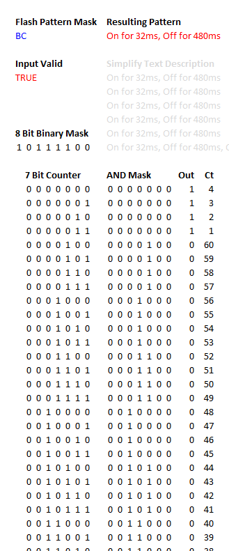
The rules for
determining the actual flash pattern from the mask byte took me a little time
to fathom out but in fact the algorithm is fairly straightforward. In words:
·
Take a
7-bit bit binary counter, incrementing every 8ms (so wrapping back to 0 after
1024ms).
·
Bitwise
AND the 7-bit counter with the lower 7 bits of the mask.
·
If the
resulting bits are ALL 0, take the
high bit of the mask, otherwise take its inverse.
·
If this is
1 the LED is ON, if this is 0 the LED is OFF.
As far as I can see,
this generates the corresponding flash pattern for all of the mask bytes that I
have tested. I put together an Excel spreadsheet that generates a text
description of the flash pattern generated by any given mask byte:
As a matter of
personal preference I have changed this from the standard value of 0xFF (8ms
Pulse, Every 1024ms) to 0xFC (32ms Pulse, Every 1024ms). This makes the
flashing LED rather more obvious and visible and makes it clear that the car is
protected by a security system.
LED Pattern Mask (Disarmed)
Hexadecimal Integer
Offset 0x89
Length 1
This byte determines
the LED flash pattern when the immobiliser is disarmed. The pattern encoding
can generate a range of LED flash patterns with one or multiple flashes per
cycle as well as permanently on or off. The pattern is encoded exactly as for LED Pattern Mask (Armed) above.
Low Battery Flash LED On Unlock
Boolean Flag
Offset 0x38
Bit 2
Active High
When set to 1, the
security LED flashes in a double pulse pattern for several seconds after
unlocking to indicate that the key fob used transmitted a low battery warning.
When set to 0, this feature is disabled. There is believed to be a further setting
which configures the number of consecutive low battery messages which must be
received before this warning is activated, although this has not been found
yet.
Low Battery Double Key Press
Boolean Flag
Offset 0x38
Bit 3
Active High
When set to 1, the key
fob button must be pressed twice when the key fob used transmits a low battery
warning. This gives the impression to the user that the key fob is failing with
a low battery. When set to 0, this feature is disabled.
In all immobilisers I
have tested this has been set to 1 enabling the feature however as a personal
preference I have disabled it.
Passive Arming Enabled
Boolean Flag
Offset 0x37
Bit 6
Active Low
When set to 0, the
immobiliser functionality (not the
alarm functionality) is engaged automatically after a certain timeout period
has elapsed. There are three different timeout values. The first applies when
the unit is unlocked but the ignition is not turned on. By default the
immobiliser engages after 30 seconds. The second applies when the unit is
unlocked and the ignition is turned on and off again. By default the
immobiliser engages after 10 minutes. The third applies when the unit is
unlocked, the ignition is turned on and off again and then the driver’s door is
opened (in a Rover). By default the immobiliser engages after 30 seconds. When
set to 1, this feature is disabled. If passive arming is disabled and the
immobiliser is disengaged, it should never engage again on its own. The current
state is maintained even when powered off and on again. This allows the
immobiliser to be effectively removed in that the user should never need to
interact with it.
For my planned alarm
project, I wanted to be able to set either the immobiliser, or set both alarm
and immobiliser. With passive arming, I can treat the key fob button as “disarm
everything ready to go” and “set the alarm”. if I only
want immobiliser functionality without setting the alarm I can just leave the
passive immobiliser to engage on its own. Using the settings below I can set the timeouts appropriately.
Passive Arm Time (No Ignition)
Decimal Integer
Offset 0x21
Length 1
Multiple of 1 Second
This is the number of
seconds until the passive immobiliser engages, if enabled, when the unit is
unlocked but the ignition is not turned on. This is a single byte and is
multiples of 1 second, so usable values are from 1s to
255s (4 minutes 15 seconds). The default value is usually 30s. If set to 0, this does not wrap to 256s; it is treated as 0s and
the immobiliser engages immediately as soon as it is disabled.
This timeout makes
sense in a Caterham installation. It is intended to immobilise the car if it is
accidentally unlocked.
From my planned alarm
project, the alarm will be triggered if the driver enters the car without
disengaging the alarm with the key fob. It would then be slightly annoying if
the immobiliser reengaged before the driver has time to enter the car and
insert the ignition key, so I have increased this from 30s to a round 240s (4
minutes).
Passive Arm Time (Ign. & Door)
Decimal Integer
Offset 0x20
Length 1
Multiple of 1 Second
This is the number of
seconds until the passive immobiliser engages, if enabled, when the unit is
unlocked, the ignition is turned on and off again and then the driver’s door is
opened (in a Rover). This is a single byte and is multiples of 1 second, so
usable values are from 1s to 255s (4 minutes 15
seconds). The default value is usually 30s. If set to 0, this
does not wrap to 256s; it is treated as 0s and the immobiliser engages
immediately as soon as it is disabled.
This timeout makes no
sense in a Caterham installation as there is no driver’s door switch. It is
intended to immobilise the car quickly after the driver leaves the vehicle, but
in a Caterham the conditions under which it applies will never occur and it is
therefore largely irrelevant.
Passive Arm Time (Ign. Only)
Decimal Integer
Offset 0xAD
Length 1
Multiple of 8 Seconds
This is the number of
seconds until the passive immobiliser engages, if enabled, when the unit is
unlocked and the ignition is turned on and off again. This is a single byte and
is multiples of 8 seconds, so usable values are from 8s to 2040s (34 minutes).
The default value is usually 600s (10 minutes). If set to 0,
this does not wrap to 2048s; it is treated as 0s and the immobiliser engages
immediately as soon as it is disabled.
In practice, the
timing here seems to be approximate. It appears as though the number specified
is the number of ticks to be counted from a clock which ticks once every 8
seconds, however as the time to the next tick can be anywhere between 0s and 8s
when the user turns off the ignition at a random moment, the first tick may
occur after a shorter elapsed time. So setting a value of 8s actually results
in the immobiliser engaging anywhere between 0s and 8s, setting a value of 16s
actually results in the immobiliser engaging anywhere between 8s and 16s etc.
With a default value of 75 (x8=600 seconds) the immobiliser may engage anywhere
between 9 minutes 52 seconds and 10 minutes after switching off the ignition.
This timeout makes
sense in a Caterham installation.
Superlocking Enabled 1
Boolean Flag
Offset 0x36
Bit 2
Active Low
Inverted at Offset 0x9A, Bit 2
When set to 0, this
enables the superlocking or deadlocking functionality found on later Rovers,
where a double-click of the key fob lock button
deadlocks the doors and prevents them from being opened mechanically. This
feature is irrelevant in a Caterham installation but if enabled can be
confusing as there are two different lock states (especially for my planned
alarm project where the indicators will be wired to flash when the alarm is
armed and different flash patterns would be produced which would be
meaningless). When using a 5AS from another vehicle, this feature may be
enabled and may be disabled be setting this bit to 1.
For some unknown
reason, superlocking appears to need both offset 0x9A bit 2 setting to 0 and
offset 0x36 bit 2 setting to 1. In all immobilisers I have seen where
superlocking is disabled, both of these bits are inverted.
Superlocking Enabled 2
Boolean Flag
Offset 0x9A
Bit 2
Active High
Inverted at Offset 0x36, Bit 2
When set to 1, this
enables the superlocking or deadlocking functionality found on later Rovers,
where a double-click of the key fob lock button
deadlocks the doors and prevents them from being opened mechanically. This
feature is irrelevant in a Caterham installation but if enabled can be
confusing as there are two different lock states (especially for my planned
alarm project where the indicators will be wired to flash when the alarm is
armed and different flash patterns would be produced which would be
meaningless). When using a 5AS from another vehicle, this feature may be
enabled and may be disabled be setting this bit to 0.
For some unknown
reason, superlocking appears to need both offset 0x9A bit 2 setting to 0 and
offset 0x36 bit 2 setting to 1. In all immobilisers I have seen where
superlocking is disabled, both of these bits are inverted.
Hazards Flash With
Alarm
Boolean Flag
Offset 0x36
Bit 1
Active Low
When set to 0, the
hazard lights are flashed with the pulsating alarm sound (in a Rover).
In a Caterham the
required wiring is not present but this is relevant to my planned alarm project
as the additional wiring will be added in order to drive the hazard lights.
Switch Closed When Bonnet Open
Boolean Flag
Offset 0x3E
Bit 0
Active High
When set to 1, in a
Rover the alarm recognises the bonnet as being closed when the input from the
bonnet switch is open circuit and open when the switch is close and the input
is short circuited to ground. When set to 0 the alarm recognises the bonnet as
being open when the input from the bonnet switch is open circuit and closed
when the switch is close and the input is short circuited to ground.
In a Caterham
installation it is important this is set to 1 if the alarm functionality is to
be activated, as the bonnet switch input is not connected. The alarm needs to
see this as “bonnet closed” or it will not engage.
For my planned alarm
project however, I wanted one trigger input which would activate the alarm when
not shorted to ground. The bonnet
switch input is the only input which may be programmed to operate in this way,
by changing this bit to 0. This may then be used to activate the alarm if the
handbrake is released, as the handbrake incorporates a switch which short
circuits to ground when the handbrake is applied.