Cloning The
Rover MEMS3 ECU
The Rover MEMS3 ECU as used with the K Series EU3 engine is not remappable in the conventional way. It does not provide published, well defined and understood interfaces for reading and writing mapping data in the way that for example an Emerald ECU does. There are however some companies offering modified maps for the MEMS3 and some were produced with Caterham-specific firmware, such as the Supersport ECU.
My ECU has a custom map and firmware loaded. I have a bit of an obsession with spare parts and a desire to maintain my car for very many years to come, so I felt very exposed knowing that I was unable to back up my ECU, especially when MEMS3 ECU hardware is readily available cheaply on eBay and the likes. I therefore set out to clone my ECU.
As well as being used to clone the ECU pre-emptively, this procedure could also be used retrospectively in the case of a failed ECU to effect a repair by transplanting the firmware into another ECU with identical hardware provided that the memory chips were not damaged. Typical failures in this ECU are more commonly ignition drivers and other high-load circuitry failing.
Let me say up front;
I am in no way attempting to “rip off” anyone producing customised MEMS3 maps.
I will not be sharing or distributing any software, this is purely for my own
legitimate back up purposes. If anybody wants an illegal copy from me - don’t
even ask! The only thing I’m sharing is the process I used to clone the ECU in
the hope that the knowledge may be useful to others who may wish to do the
same, or who want to understand the ECU a little more. However if anyone
already has a modified ECU and a legitimate reason to move the firmware onto
another ECU, such as a fault with the original, I would be happy to help.
Let me also say that I have read many internet forums threads which discuss cloning the MEMS3 ECU and which after many pages eventually fizzle out without reaching a conclusion. A lot of these plans revolve around various Chinese clones of chip tuning tools and my own experiences with these are particularly disappointing. The process I describe below was successful. I have documented the complete process I went through to produce a fully working and robust clone of my ECU. In the process of research I’ve now made quite few clones of various MEMS3 ECUs and I haven’t lost one yet.
I don't think anything that I've done hasn't been done many times before, but in all of the discussions I could find on the Internet, those who knew what they were doing always seemed to be very cagey and protective of the information, presumably for commercial reasons. My intention here is to put it all out in the public domain, clearly and openly documented.
The overall plan was to open up the case and identify the memory chips used to store to mapping and firmware, remove them, copy their contents into a file on the PC for backup, copy these files to new memory chips and then use these chips to replace the memory chips in another ECU. In theory this should result in the new ECU inheriting all of the firmware and data of the old ECU - but the idea was dependent on a number of assumptions. These included that the firmware was all stored in separately identifiable chips and not in programmable elements within the microcontroller, and that there was no explicit copy protection that checked things such as the processor serial number.
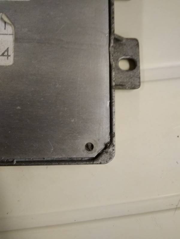
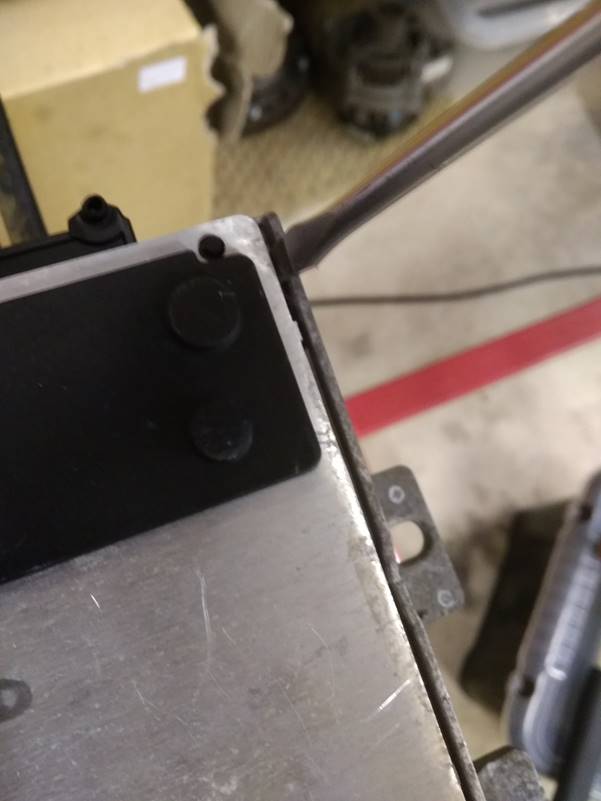
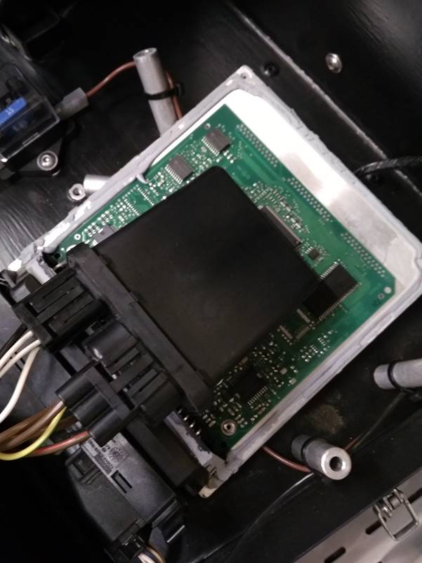
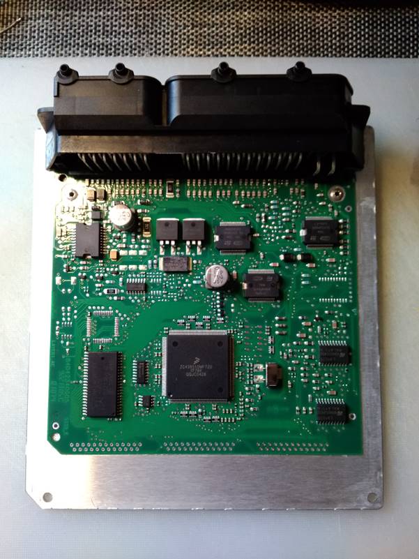
So the first challenge was to get the case of the source ECU open without damaging the circuit board. I bought myself a cheap Rover 1.4 MEMS3 ECU and opened that up for a good look first to check what I might be at risk of damaging. The circuit board is bonded to the flat aluminium “lid” so it is important not to bend this much when removing it, but this is bonded firmly to the cast case using a very strong and hard silicone sealant. The circuit board is actually shorter than the full length of the case though, and so at the narrow end of the ECU away from the connectors there is a little more scope for flexibility. In the end I found it was possible to split the lid off the case starting from the flat side in this corner:
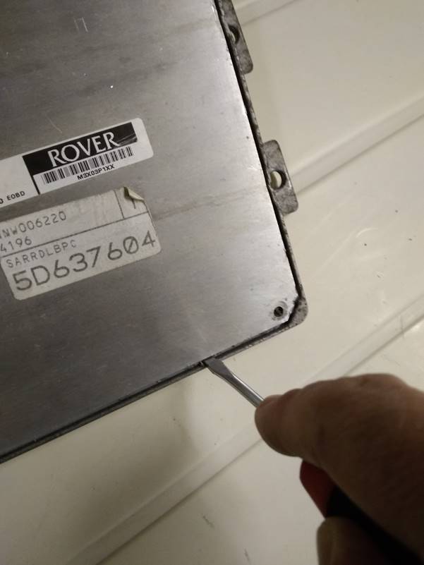
The trick was to insert a small flat screwdriver very firmly and prise the lid upwards. To avoid bending the circuit board, I only lifted the corner a tiny amount until the silicone sealant could be heard splitting. I then worked along the bottom edge moving along a couple of centimetres at a time, again lifting it just until it could be felt to separate. I then worked up the two sides towards to connectors and finally lifted the lid, splitting the sealant around the connector. If you make sure you push down hard on screwdriver so that you lift the lid from deep down, any marking of the lid will be on the inner edge and invisible when reassembled.
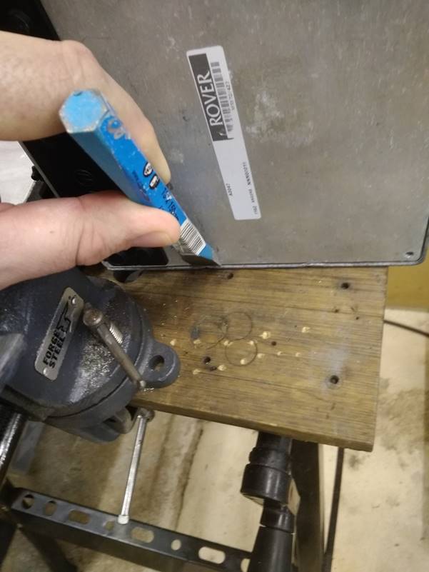
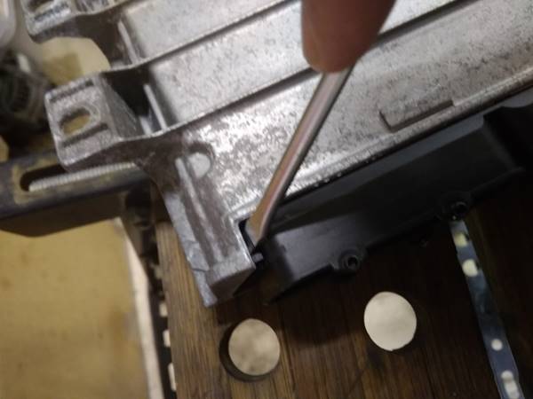
There are a couple of points along each side of the ECU where the cast casing is staked in to grip the lid. It can make things a little easier if these staked points are knocked back first. I did this by placing the ECU on its edge on a wooden work bench and placing a cold chisel against each stake, giving it one good firm clout with a hammer. If you do this, make sure the case is well supported on a flat surface and don’t use too sharp a chisel, it is all too easy to cut or fracture a lump out of the edge of the casing.
At the connector end of the casing, the silicone sealant passes up the sides of the plastic connector housing and across the top. This can make it particularly stubborn to get the casing open at this end. If you use force to prise the case open as shown below, there is a good chance of bending the panel in a way that makes it hard to flatten again afterwards.
Instead, with some care, it can be best to separate the connector by levering as shown below:
Once the lid is off the case as shown below, check the lid panel, especially around the corners where it may have been slightly bent. If so it can be straightened out by clamping the edge of the panel in a vice and gently pulling it back into shape. The panel needs to flat in order to fit back into the case and seal at the end of the process. Be very careful not to damage the printed circuit board which is firmly bonded to the lid.
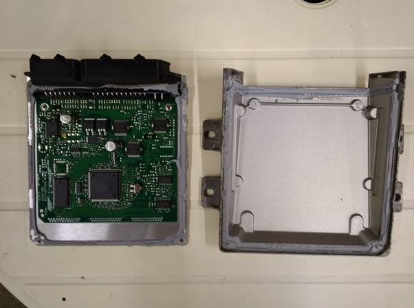
With the case off you can see what I meant about a little more scope for flexibility at the bottom.
NB: Since writing
this, I have opened up a Rover 216 ECU and discovered that the entire circuit
board had been sealed with what appeared to be a layer of silicone sealant
sprayed on. The whole circuit board was covered in a thin clear silicone layer,
which would have made soldering impossible. If you come across this, you will
need to strip the silicone layer from the entire circuit board before
proceeding. To remove it I plastered it liberally in Unibond Silicone Sealant
Remover. I spread a large quantity of the silicone remover over the board and spread
it with a small paintbrush, working it liberally into all of the component
connections. The silicone used, although soft and rubbery to touch, does seem
to be fairly resistant to softening with silicone remover. The instructions for
the silicone remover say that you should leave it on for at least 3 hours. I
left it on for 12 hours and then scrubbed the board clean with a toothbrush
under hot running water, using lots of soap liquid. It still hadn’t completely
softened the silicone and I had to apply a second coat which I left for a
further 24 hours. I finally removed it all from the board using a toothbrush
and hot soapy water as above. The dried silicone remover is somewhat oily and
smelled of paraffin; Gunk Ultra degreaser seemed quite effective at removing
the last traces. Make sure you really get all residual traces silicone remover
off, working well between the pins of the ICs etc. I used a long bristled nylon
kitchen brush to get in between the pins of the main connector headers. After a
final clean and blow dry, the board looked pretty much the same as the others I
had seen and soldering was no problem at all.
I repeat here the
warning which I mention regarding Unibond Silicone Sealant Remover later in
this article; Warnings on the label say it can cause severe chemical skin
burns. I ended up with very sore fingers. Wear gloves!
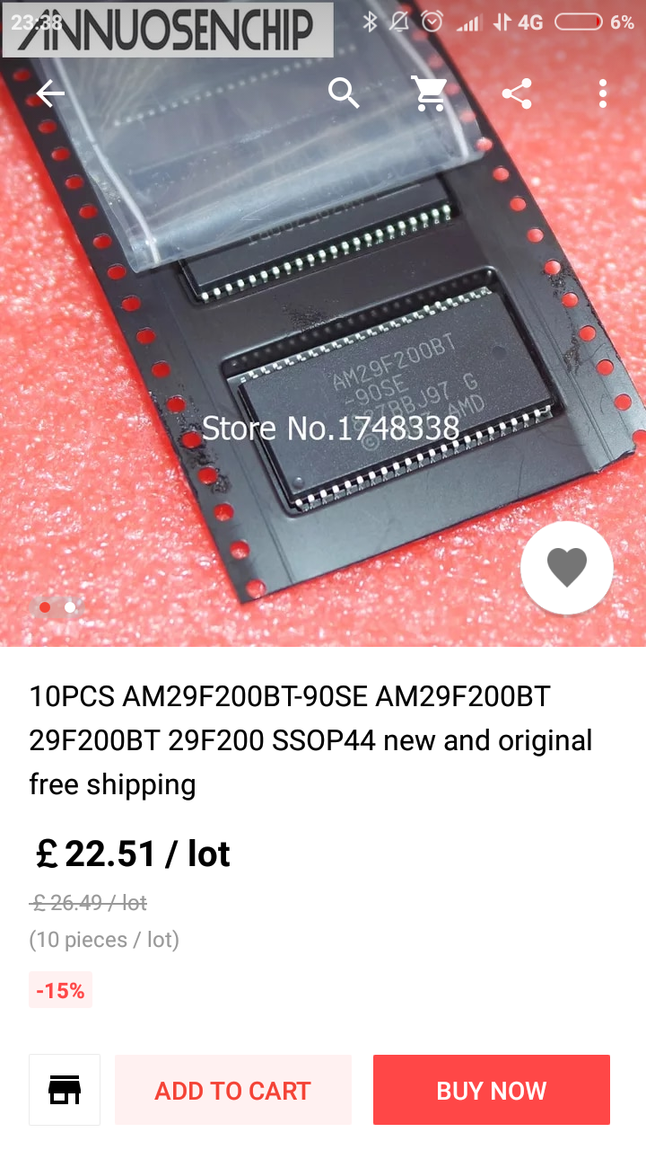
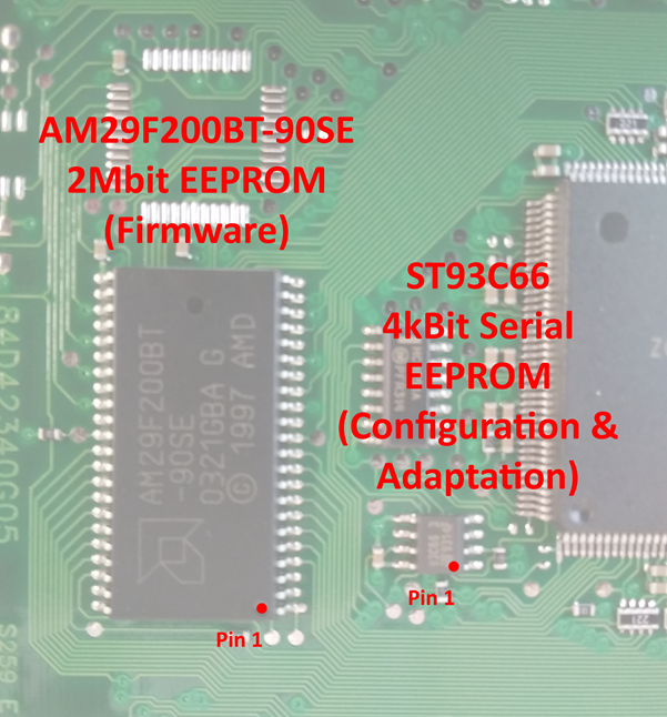
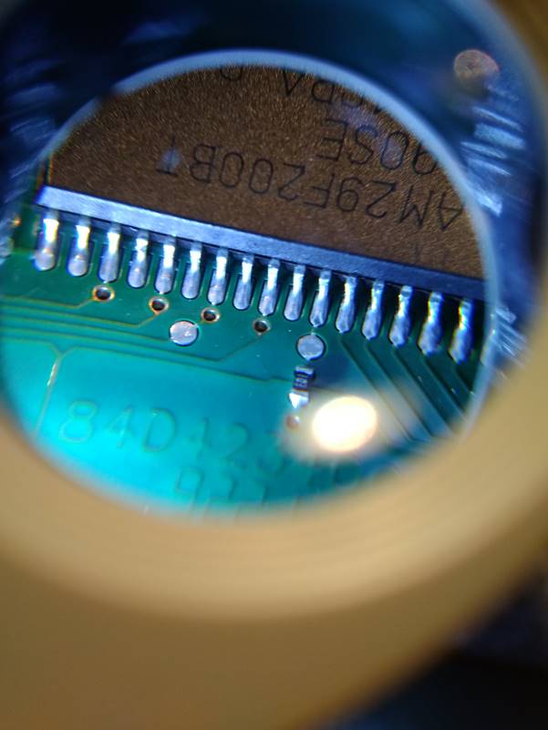
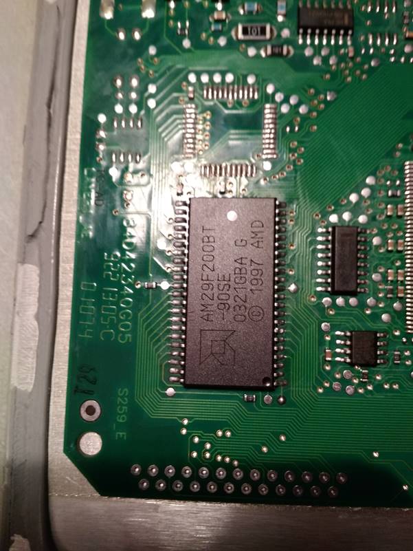
The memory chips are readily identifiable. There is a 29F200 2Mbit flash EEPROM chip (specifically an AMD AM29F200BT-90SE, and this exact variant should be used when buying new chips, the “B” signifies a later B version of the design, “T” for top memory address boot sector, “90” nanosecond access time (speed) and the “SE” version covers the full automotive temperature range). This is an obsolete chip but still obtainable if you shop around, I ended up ordering a pack of 10 from China via a seller on AliExpress for £22.51, or £2.25 each. You will see later on why I recommend using new memory chips rather than reprogramming the existing ones - the process of getting them off the PCB is pretty aggressive. Given that new chips are still available I would prefer to replace them than to rely on the chips in the long term after putting them through that, although in reality if you were unable to source replacements, reprogramming the original chips would probably be perfectly satisfactory.
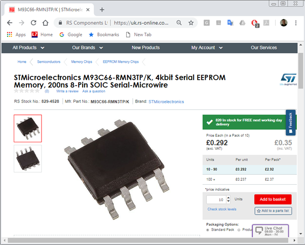
There is also a 93C66 4Kbit serial EEPROM. This also comes in various flavours - some manufacturers provide A/B/C versions. The C version is configurable for 8 bit or 16 bit architecture, the A and B versions are fixed 8 or 16 bit. The chip is simply marked ST93C66. The chips produced by ST are all of the configurable C variant. This is also an obsolete chip and finding an exact much proved a lot harder, however it has been superseded by the M93C66 which is still current and intended to be backwards compatible with older designs but with twice the maximum clock frequency and a wider supply voltage range. The exact version which is compatible is ST part number M93C66-A125 or M93C66-RMN3TP/K (“R” is 1.8V to 5.5V supply, “MN” is SO8 150 mils surface mount package, “TP/K” refers to the packaging and manufacturing plating process used). I’ve tested this chip in the MEMS3 quite extensively and it seems perfectly happy with the upgrade. These are readily available in small numbers from the usual suppliers such as RS Components, Mouser Electronics etc. I bought a pack of 10 from RS for £3.50, or £0.35 each.
It seemed logical to me that the larger 29F200 would be used to hold all of the static firmware; the operating software and maps, with the much smaller 93C66 holding dynamic configuration information such as immobiliser security code, adaptation data and DTC codes etc. So essentially the contents of the 29F200 would be read-only to the ECU in normal operation (other than when being flashed with new firmware) and the 93C66 would be read-write and used to store information that changed at run time. Experiments swapping individual chips between ECUs confirmed this to be the case. Cloning both the 29F200 and 93C66 into a target ECU therefore leaves it with not only the firmware and mapping of the source ECU but also the immobiliser pairing, TPS calibration and engine adaptations.
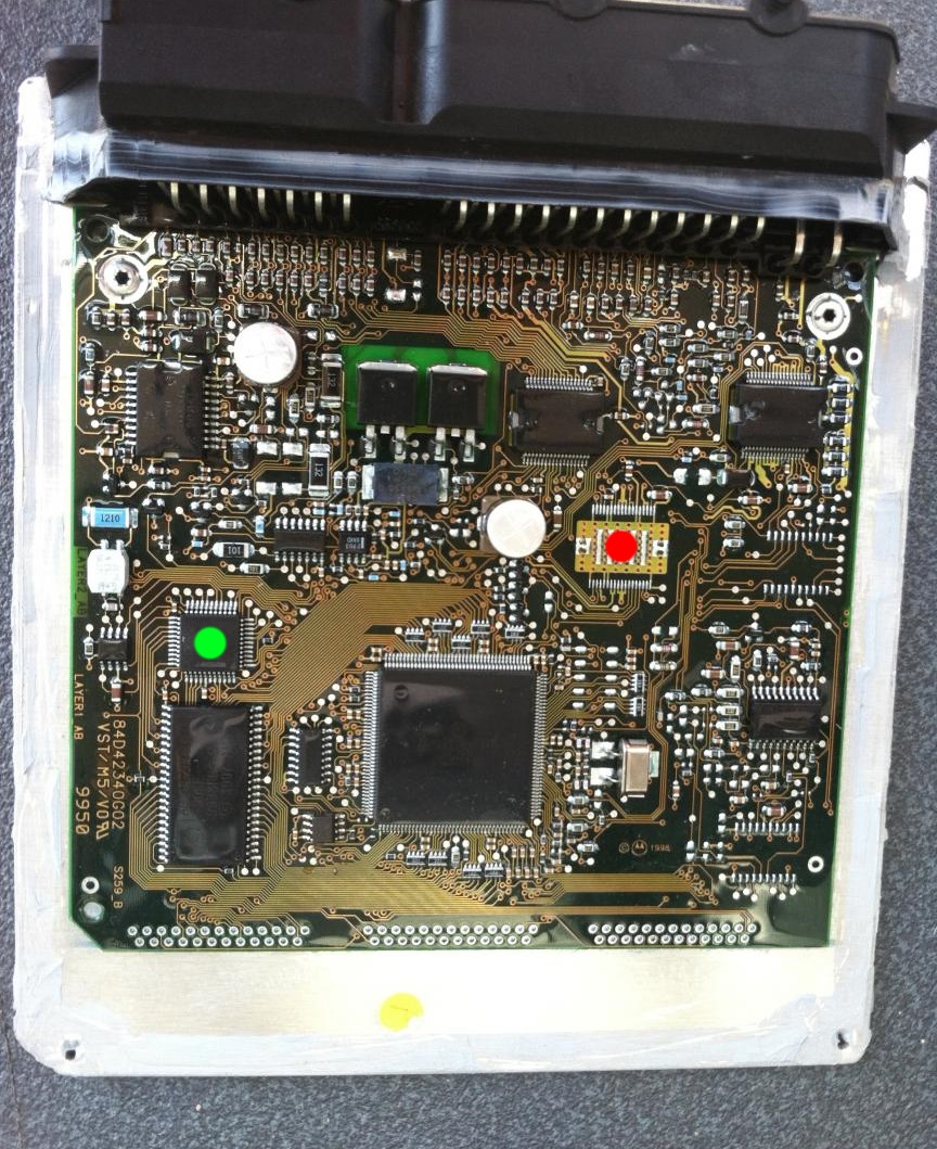
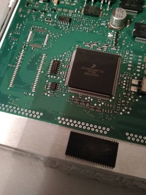
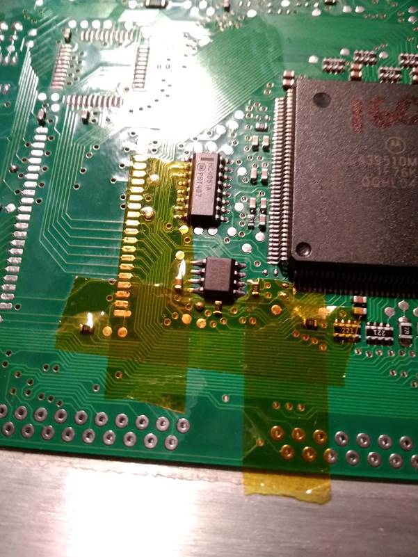
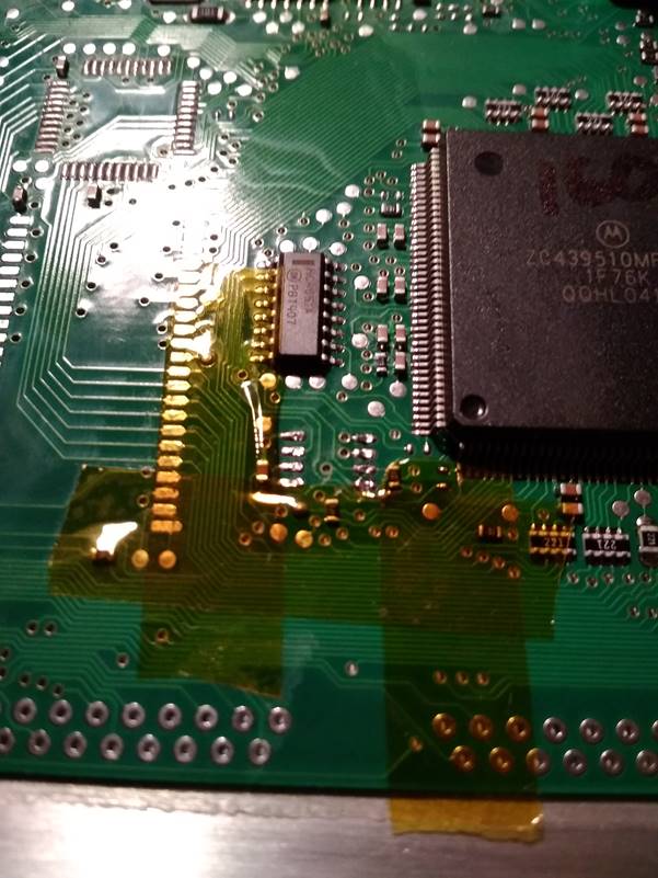
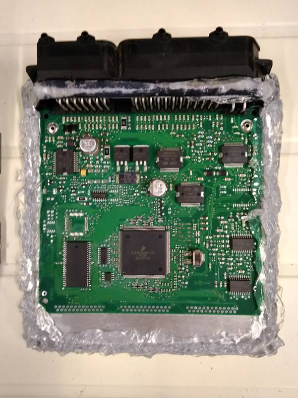
At this point it is worth mentioning that the first “M” in “MEMS” stands for “Modular”. Not all MEMS3 ECUs are created equal. There are a number of sets of solder pads in my ECU for chips which are not present, which may be present in other ECUs equipped with different modular options. There are also chips present in my ECU which are not present in some other MEMS3 ECUs. In the picture below of another ECU, the red dot highlights a chip which I have which is not present and the green dot highlights a chip which I do not have. As far as I can make out, the extra chip I have seems to be associated with VVC ECUs (mine is a VVC engine) while the missing chip seems to be associated with an automatic gearbox, although I may be wrong here.
The point is that there’s no guarantee that the firmware from one ECU will work in another ECU which is not identical at a hardware level. To be on the safe it is best to use another ECU with the same NNNxxxxxx part number, although some ECUs with different part numbers may still have identical hardware. For example earlier MEMS3 VVC engines from the MGF Trophy 160 used an NNN000100 ECU whereas the later MEMS3 VVC engines from the MG TF used an NNN000160 ECU. As far as I can tell the only differences between these two parts are in the firmware loaded and the hardware is identical (at least as far as the systems we use in our Caterhams are concerned); I have been able to swap maps between them without problems.
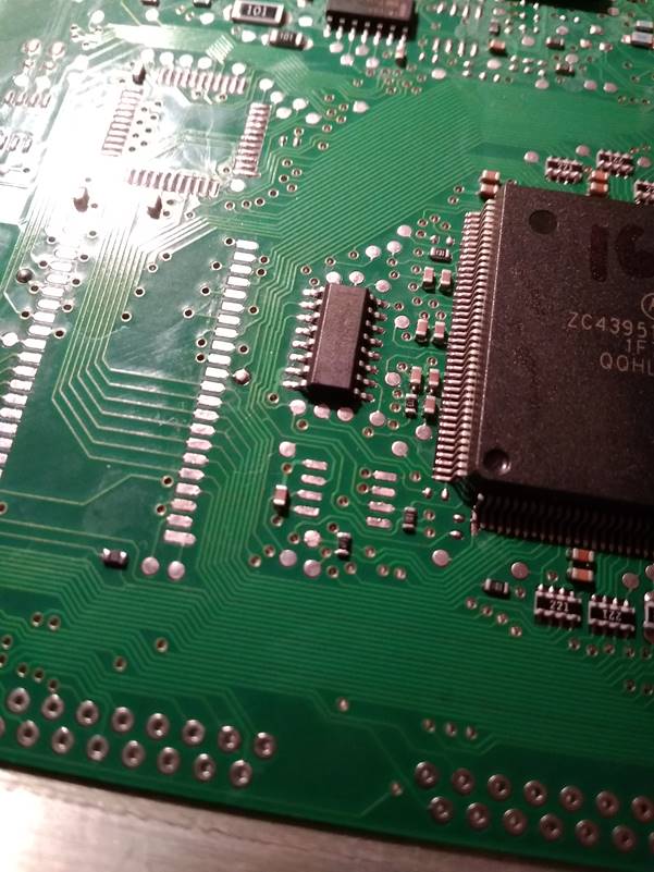
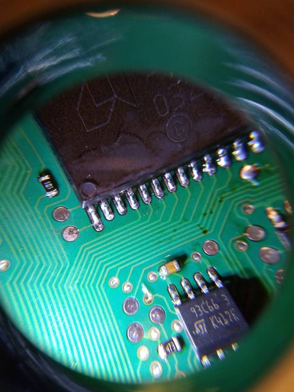
The picture below shows the two chips. The 29F200 is a 44-pin PSOP44 package. The 93C66 is a much smaller 8-pin SOIC8. Pin 1 of the 29F200 is clearly marked with an indented dot. Despite the manufacturer’s documentation for the 93C66 specifying that pin 1 will be similarly marked, I couldn’t see any identifying marks on the chip at all. As it is critical to make sure that the chips are replaced in the correct orientation, I tracked down which was pin 1 by identifying the two power supply pins on both chips and checking which pins on the 93C66 were connected directly to the known supply pins on the 29F200. The results were only compatible with pin 1 being in the same position on both chips as shown below.
Both components are surface-mount devices, soldered to the top side of the board only, rather than with leads passing through holes.
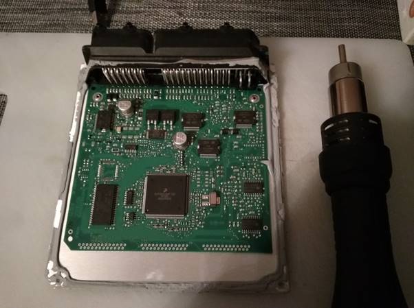
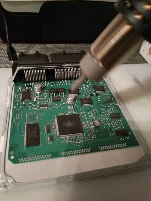
Tools used to remove the 29F200 were a solder rework hot air gun as shown below …
And a high temperature vacuum pickup pen as shown below.
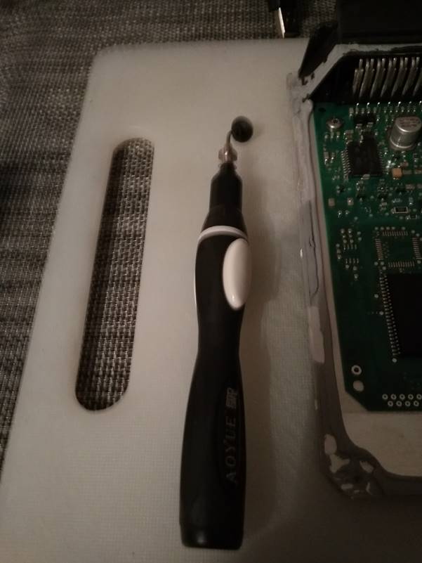
The basic idea is to use a jet of temperature-controlled hot air to heat and melt the solder on the pins of the chip while gently lifting it with the vacuum pen, allowing the chip to gently lift free as the solder reaches melting point. The issue turned out to be the construction of the PCB itself. The PCB is glued very strongly to the aluminium plate for robustness, but if you do peel one off (which will destroy it!), you find that rather than a rigid board it feels more like a flexible copper plate; I think that the metal layers and ground planes form the majority of the board with thin mica layers between them, meaning that the majority of the board is metallic and therefore a good conductor of heat. Once bonded to the aluminium plate it turns out to be very difficult indeed to heat the all of the chip pins simultaneously to the point where the solder melts.
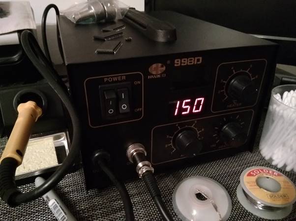
In the end the technique I had to use was to preheat the whole board for several minutes using air at 150°C (actually in later attempts I preheated the whole metal panel from the back side with a large mains-powered heat gun, heating evenly just to the point where I could not bear to hold a finger on the metal for anything more than half a second or so, then flipped the board over and proceeded as shown below, working quickly before it cooled down)…
Then turn the
temperature right up to 450°C and
the airflow to maximum.
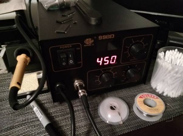
Even with these aggressive settings it took several minutes of evenly heating the pins at close range before the chip could be lifted off, by which time the whole chip package was extremely hot. I fully expected the chip to be totally destroyed by the time it came it off, but after doing four boards in this way every chip was fully functional once it had been allowed to cool down so they do appear to be more robust than I anticipated. Because of this aggressive treatment I decided not to reuse the chips which I had removed but to use brand new chips in every case.
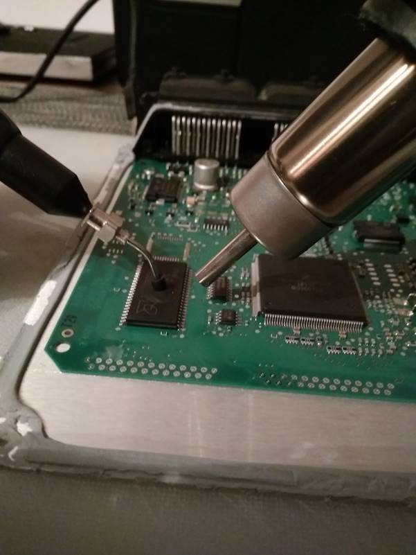
Eventually the chip can be gently lifted free with the vacuum pen and allowed to cool. Once free, allow everything to cool thoroughly before doing anything else. Do not be tempted to use force to lift the chip or the board will be damaged. When heated with an air jet it becomes quite delicate. The force provided by the vacuum pen is just enough to lift the chip without doing any damage once the solder melts.
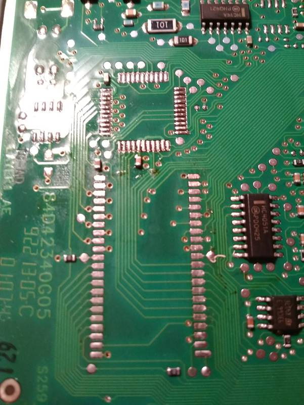
Once everything had cooled down, the next job was to clean up the excess solder on the pads on the circuit board. For this job I painted the solder pads liberally with alcohol-based liquid flux and then applied copper solder mop braid with a soldering iron, wiping it slowly down each line of pads.
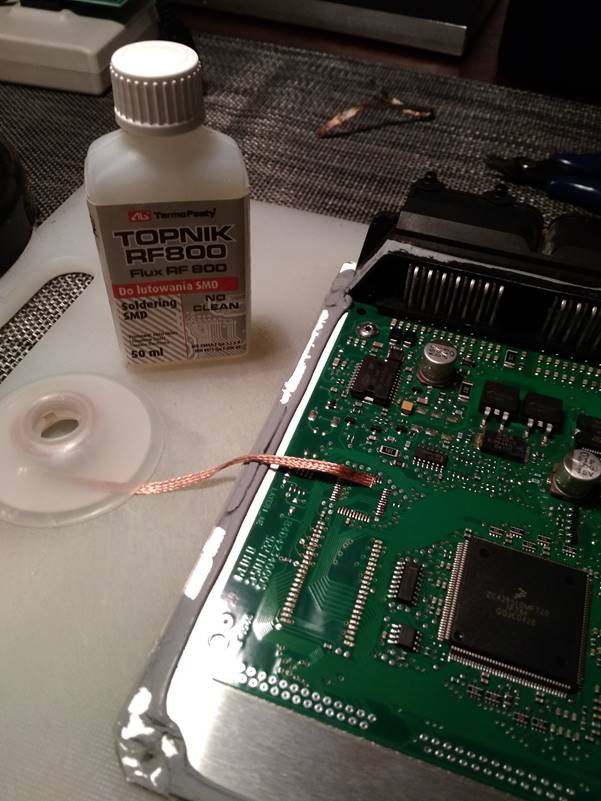
When finished I cleaned the pads with pure isopropyl alcohol on a paper wipe to remove the flux residue.
The 93C66 chip now needs to be removed following a very similar procedure. Due to its smaller size, it comes off a lot more easily. There are a number of tiny (sub-millimetre) surface mount resistors mounted very close to the chip. If you use 450°C and maximum airflow on this chip it comes away in a couple of seconds but the surrounding components will also become loose and blown away by the airflow, leaving you with a complicated repair using solder past reflow. Use a gentle airflow on the smaller chip, focused very precisely on the chip itself. In this way most of the surrounding solder is undisturbed and where it does melt the components do not move before the solder sets again.
In addition, high temperature Kapton adhesive tape may be used to provide a degree of shielding and to anchor adjacent components in place during the application of hot air.
It is very difficult to lift a chip this small with a vacuum pen. Instead a pair of fine tweezers may be used, but be very careful not to pull the chip too hard as this may cause the tracks on the PCB to become damaged. Just the very lightest touch is needed, allowing the chip to come away only as it becomes free.
With care the chip should come away cleanly, leaving the surrounding components undisturbed.
The
Kapton tape may then be very gently peeled off and the solder pads carefully
cleaned up with alcohol based liquid flux, solder mop braid and finally pure
isopropyl alcohol.
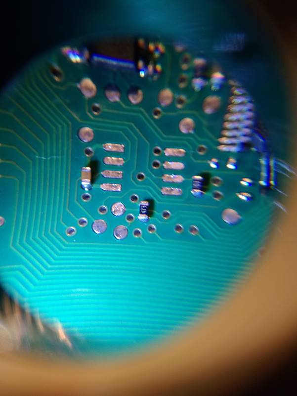
It is worthwhile at this point to make a very close inspection of the surrounding components with a jeweller’s loupe to make sure that noting has been dislodged or damaged and that no remedial work is needed.
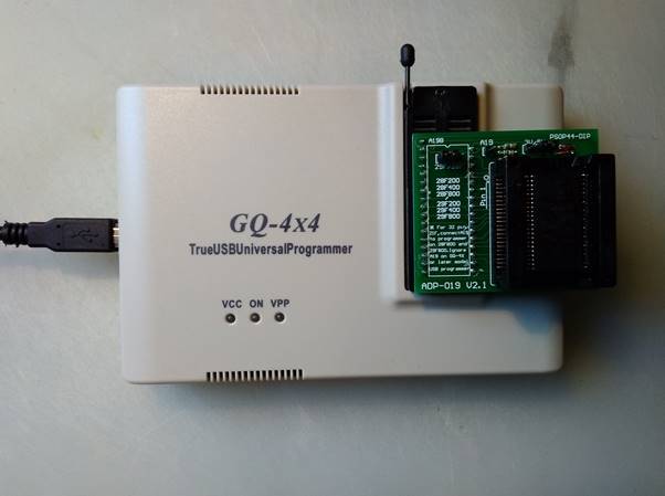
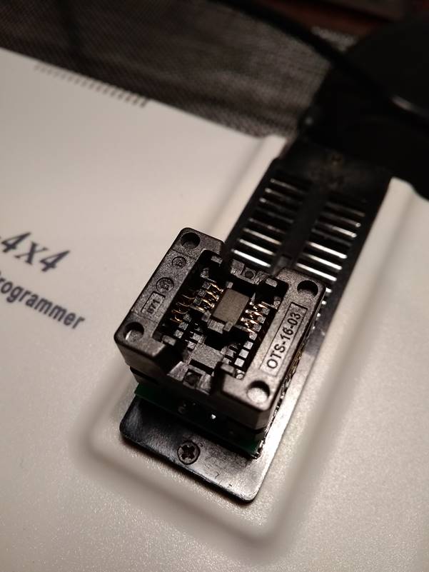
This whole process then needs to be repeated for the target ECU. At this point you will have two identical ECUs with the memory chips removed. Be careful not to mix them up. I then moved on to the process of copying the contents of the memory chips. For this I used a GQ-4x4 universal programmer, which is readily available online. It runs from a single USB connection and comes with software that works with recent versions of Windows. In my case I used a Windows 7 64-bit laptop.
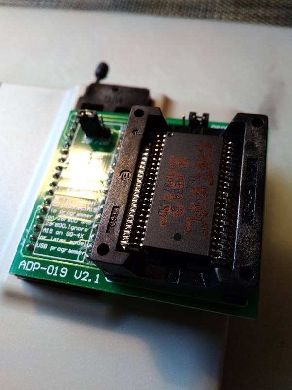
To mount the PSOP44 surface mount package of the 29F200 into the ZIF socket of the programmer, an ADP-019 adapter is needed. This has a couple of hardware jumpers which need to be set to “29” family and “5V” and mounted as shown in the lower pins of the ZIF socket.
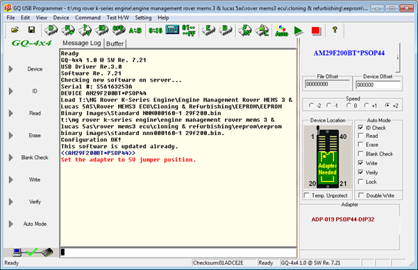
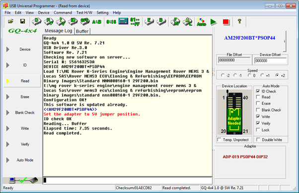
When the software launched, I clicked on “Device” and selected “AMD” as the manufacturer and “AM29F200BT*PSOP44” as the device. It is important to select the correct device. As mentioned earlier there are numerous variants of the 29F200 chip. The software then displays instructions for mounting the device in the adapter and setting the jumpers as required.
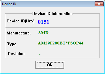
With the memory from the source ECU loaded into the adapter, I clicked “ID”. The programmer then confirmed the identity of the device loaded. This is the point where you find out whether the chip has survived the desoldering process or not! In my case, every chip I’ve removed using this procedure has been fine. What I did find however was that the connector clip on the adapter is not 100% reliable, probably largely due to small amounts of residual solder and flux residue on the chip pins. If the device doesn’t identify correctly, try removing and repositioning it in the adapter and double-check the orientation. On some I had to do this a few times to get a good read of the chip ID, so there were obviously some pins which were not making a good connection.
Once the chip was identified correctly I clicked “Read” and the contents of the chip were read into a buffer in a few seconds.
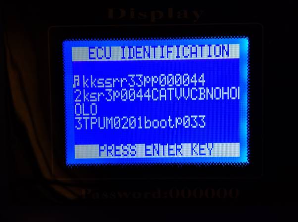
The chip contents are just binary data and there is very little recognisable. There was a little bit of character data which could be matched with the ECU identification string displayed by a T300 key programmer which looked promising. At this point I saved the data to a file. The software lets you load and save the contents of the buffer to raw binary .BIN files. This saved copy would be my long-term backup of the ECU firmware and mapping.
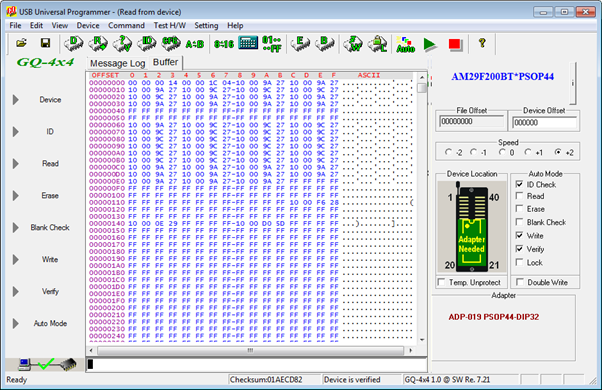
I then loaded a new 29F200 chip into the programmer and once again clicked “ID” to verify communications. As supplied the chip is blank, which in this case means every single binary bit is a “1” and the buffer will show FF hex for every bite if read. Just to be sure I clicked “Erase” and then “Blank Check” which verifies that the chip has been successfully erased and that all of the addresses read FF hex. I then clicked “Write” to write the contents of the buffer, loaded from the source memory chip, to the new target memory chip. This results in the new target memory chip being a complete and perfect clone of the source, and contains a clean copy of the firmware and mapping ready to be soldered into the target ECU.

An ADP-004 adapter is also available for the SOIC8 surface mount package of the 93C66 which can then be read and written in almost exactly the same as shown below for the 29F200. The main difference is that the 93C66 does not support the “ID” function. I selected “ST” as the manufacturer and “M93C66 (8BIT)” as the device. The 93C66 chips installed in the ECU do not have pin 1 clearly marked as described above. On all of the devices I have seen, pin 1 in the pin adjacent to the ST logo.
As the data is read serially from this chip on a single pin, you are unlikely to get incorrect data due to a bad connection. Rather than relying on getting a good ID from the chip to verify communications, so long as the buffer appears to contain variable data after the read operation it is most likely to be correct. If the buffer contains all hex 00 or all hex FF, the read has not succeeded. The contents of this chip usually seem to consist largely of a block which is repeated twice - my guess is that it implements some kind of fail-safe with an active copy and backup copy of the configuration data to allow it to recover if writing the configuration data files. If you see that general structure, you can be fairly sure that the read has succeeded. If the device doesn’t read successfully, try removing and repositioning it in the adapter and double-check the orientation.
Soldering the chips back in is a fiddly operation. Both the 29F200 and the 93C66 are done in exactly the same way. Again take extra care not to damage or disturb surrounding components, especially when soldering the 93C66 chip.
There are numerous techniques for soldering surface mount chips, in particular the use of a solder paste which then melts and flows around the pins when hot air is applied or a technique known as “drag soldering”, where a soldering iron is run along each row of pins dragging a bead of molten solder. In the end I found that neither of these techniques gave satisfactory results and I was plagued with poor dry joints and almost invisible whiskers of solder bridging the pins. I think the main problem was the heat sinking effect of the metal back plate to which the circuit board is bonded as mentioned above. Below I describe the procedure I used which gave really neat results and with practice produced results which were practically indistinguishable from the factory soldering.
The first thing I did was to align the chip very carefully on the solder pads on the board and tack the corner pins with a spot of solder. There’s no need to worry about getting a good joint at this point. You need to ensure that the pins of the chip sit centrally within the area of the pads all the way along both sides. Any misalignment makes the final soldering process a lot harder. The pins are only spaced 1.27mm or 1/20” apart so soldering takes a steady hand. A jeweller’s loupe allows a close inspection of the pins and any finished soldered joints. Make absolutely sure at this point that the chip is correctly oriented, referring to the diagram earlier showing the location of pin 1. Tack one corner and inspect. If not correctly aligned the solder can be melted by touching the soldering iron and the chip position can be adjusted. Once happy with one corner, tack the corner diagonally opposite and inspect again. Only once you are completely happy with the alignment of the whole chip, tack the other two corners in place.
Don’t worry at this point about spattering of molten solder on the board, whiskers of solder, dry joints etc. The purpose here is just to fix the position of the chip correctly.
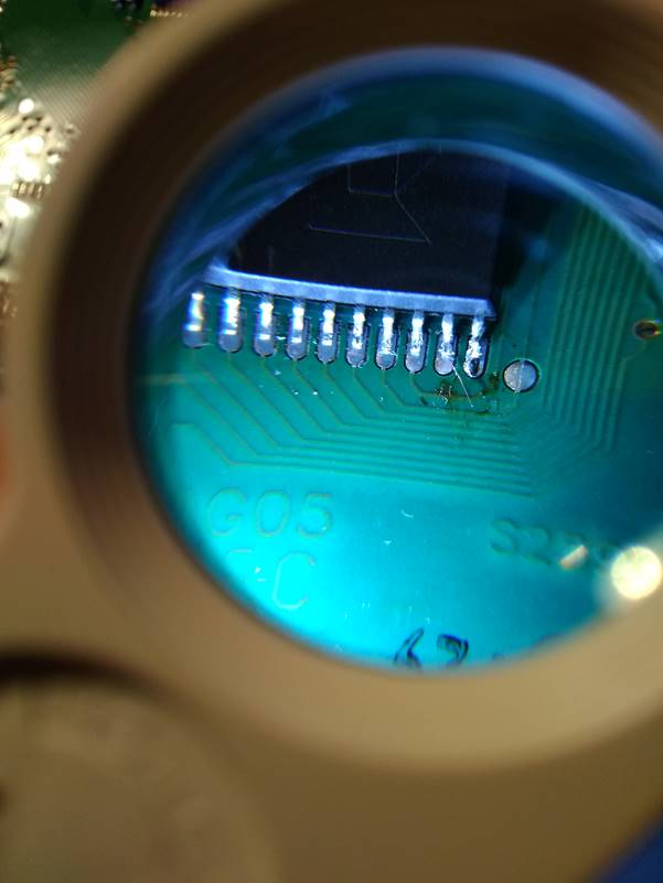
I then drag soldered down each side of the chip in turn. Using plenty of alcohol-based liquid flux on the pins and pads I applied a little solder to one end and slowly dragged the iron along the line of pins allowing the molten solder bead to flow around each in turn. When finished this resulted in most of the pins being soldered into place but numerous poor dry joints and bridges between pins. You can see in the picture below that the 7th pin from the left has very little solder on the chip pin and that there are bridges between several pins to the right of the picture. You can also see solder spattering and flux residue on the board. At this point the chip is at least firmly mechanically attached.
I then carefully reflowed each pin one by one by hand using large quantities of alcohol based liquid flux to produce much better and more even soldered joints, then cleaned up with pure isopropyl alcohol on a paper wipe to remove any solder spattering flux residue as shown below. The technique was to put very liberal quantities of flux over a few adjacent pins until they were literally bathed in fluid, then just touch the tip of the soldering iron to each pin in turn just long enough to allow the solder to melt. A little extra solder could be added carefully if required. The action of the flux and the surface tension of the solder encouraged the solder to flow neatly around the pin and pad and caused any bridges to pull back in, leaving clean joints. The flux used was of the no-wash type which does not leave corrosive residue and doesn’t not really need to be washed off afterwards but for neatness and to allow a thorough inspection I cleaned up carefully with pure isopropyl alcohol.
You can see in the picture below that the final result was a lot neater and very similar to the original factory soldering.
And here is the finished chip.
At this point I plugged the ECU back into the car for a quick test. If the ECU doesn’t run the engine at this point, the most likely issue will be a poor connection on one of the soldered pins or a tiny bridge between two pins. Typical results when the memory chip is not soldered correctly always seem to be the same; the failure mode is that the fuel pump runs continuously and the engine will not fire. This seems to be the default initial state of the driver hardware when the microcontroller does not run. Until I’d had a bit of practice soldering these chips, my first few attempts resulted in a no-start condition and I was quite convinced that I’d damaged the chips during the process, but in every case the fault came down to soldering and I was able to resurrect the ECU by paying careful attention to each soldered joint. Look carefully for bridges and dry joints using a jeweller’s loupe and resolder any pins where you are not 100% happy, using copious amounts of liquid flux to help the solder flow properly.
With the ECU mounted in the Car, my T300 key programmer showed the same ECU identification data for the target ECU as for the source ECU. This included the string “CATVVC”, for Caterham VVC, which was not present in the Rover identification data. A quick test drive also confirmed that the car clearly was running on the modified map and driving as expected.
So from an electrical point of view, that was it. Mission accomplished!
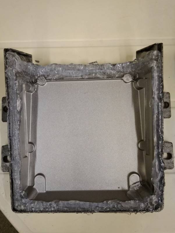
All that remained was to clean up the silicone residue and seal the case against moisture ingress again.
To remove it I plastered it liberally in Unibond Silicone Sealant Remover. The silicone sealant used is particularly hard and tough. The instructions for the silicone remover say that you should leave it on for at least 3 hours. On bathroom sealant this is enough to reduce the silicone to a soft jelly, but on this stuff it did very little. It took 12-24 hours to soften the sealant to the point where it was easily removed. Just give it time, it does work eventually.
The silicone remover comes with two warnings. Firstly, do not use on aluminium. I didn’t have much choice, so I ignored this. If didn’t mark the metal at all and I didn’t see any problems at all. Secondly, it says it can cause severe chemical skin burns. I did have a choice here, but I also ignored it. I ended up with very sore fingers. Wear gloves!
Here it is applied to the lid.
And the case.
I scraped the softened silicone off with a plastic scraper. Be very careful not to slip with the scraper or you will remove surface mount components from the circuit board. I then cleaned the board thoroughly.
My cleaning process may be appear to be slightly unorthodox and aggressive. Feel free to clean up however you want. In my case I convinced myself that there was nothing on the board that was likely to be damaged by water, so I gave it good scrubbing with a toothbrush and washing up liquid under a hot tap! I then cleaned it further with a toothbrush and plenty of isopropyl alcohol, followed by a rinse and a very thorough blow dry using an air blow gun on my compressor. No harm was done. Just make sure it is completely dry before even thinking of powering it up again. If in doubt, leave it in a warm airing cupboard overnight.
Here is the finished result:
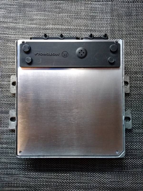
Before reassembly I decided to give the whole thing a good clean up. Here is the cover plate after working it over with Scotch Brite abrasive pads. OK, so I lost the original Rover part number labels, but what was inside no longer corresponded with the original labelling anyway so I didn’t mind.
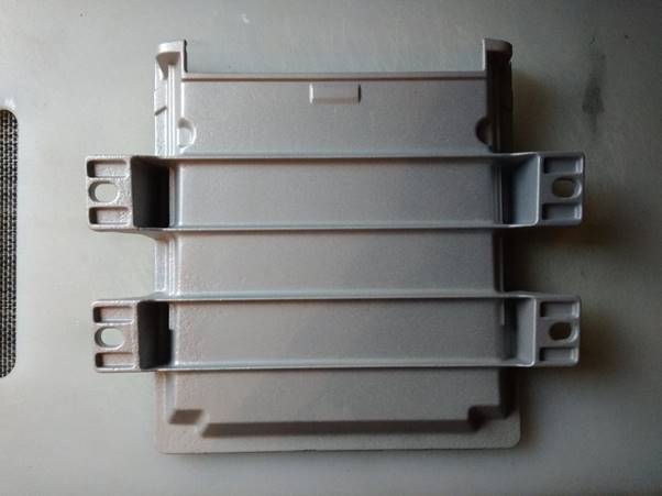
I also got a local auto restoration workshop to blast the casing for me while it was separated in order to remove all of the powdery corrosion and dirt. After blasting I gave it a good wash to remove any residual blast media.
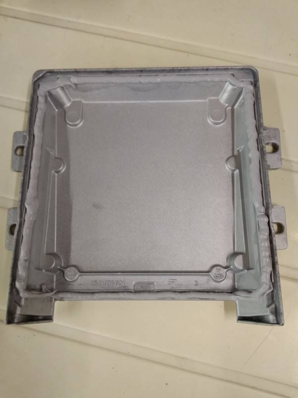
Finally I used JB Weld Ultimate Grey sealant to seal the casing again. This is a particularly tough and durable RTV silicone which was a good match for the sealant originally used, in terms of strength, hardness and colour.

A good thick continuous bead around the edge of the casing as shown below should ensure that the ECU is full environmentally sealed and waterproof as it was before I started. I erred on the generous side as I don’t envisage this ECU ever coming apart again, especially as I am now able to produce ECUs with my custom mapping to order.
The cover plate then pressed firmly into place with some evidence of the silicone squishing out all around the edge, suggesting it had made a good seal.
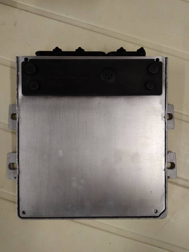
Job done! The cloned ECU is now installed in my car looking very shiny and running very nicely.