Remapping the Rover MEMS 1.9 ECU
Download
Link: https://andrewrevill.co.uk/Downloads/MEMSTools.zip
This one has taken some time to bring to a conclusion, but I now have a working remap solution for the MEMS 1.9 ECU.
Overview
- The MEMS 1.9 ECU can now be remapped and reprogrammed.
- This enables remapping of non-VVC EU2 MG Rover, Caterham etc. It also enables remapping of MEMS 1.9-base SPI Minis and Rover T-Series including Morgans.
- My MEMS Mapper software has been updated to fully support the MEMS 1.9 ECU. This includes:
- Visual editing of tables and scalars, now with full ex-factory PETA definitions.
- Firmware immobiliser delete. Properly and permanently disables the immobiliser function on MEMS 1.9.
- Dual map, live switching. I’ve been able to replicate the dual map features I implemented on MEMS 2J and MEMS3 right across the MEMS 1.9 range. With switch or throttle-based inputs.
- Mark Stacey at Kmaps is now able to offer remaps using my modified MEMS 2J and MEMS 1.9 ECUs (as well as MEMS3 as always). If you want a professional remap on a MEMS 2J Caterham EU2 VVC, Elise, MGF VVC, Mini MPI, Rover 200 Coupe etc., or a MEMS 1.9 Caterham EU2, Elise EU2, MGF, Mini SPI etc. then Mark is the man to talk to!
Details
The MEMS 1.9 ECU was never designed to be remappable, so enabling remap is a much more complicated process than on the later MEMS 2J and MEMS 3 ECUs. It is based on an Intel AN87C196KD microcontrollers that has internal, One-Time-Programmable ROM. There is no separate ROM chip that can be replaced with programmable EEPROM, and the internal ROM cannot be reprogrammed once written to.
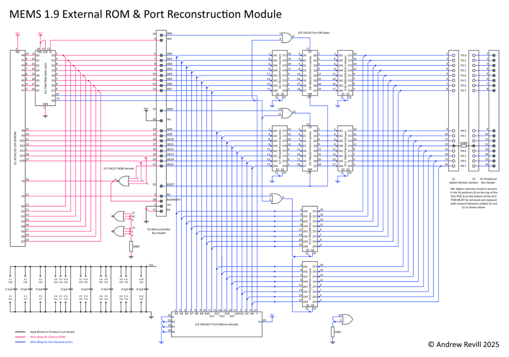
It is possible to add an external EEPROM, but this comes at a cost. The microcontroller has one set of pins which can function EITHER as an external memory bus OR as IO ports, but not both at the same time (at least not without a complex demultiplexing scheme and limited functionality). Unfortunately, MEMS 1.9 uses the IO ports affected (PORT3 and PORT4) extensively, so as soon as you add external programmable EEPROM, you lose control of the main relay, fuel pump, IACV, injectors etc. The only practical solution is to develop a remap expansion board which contains not only external EEPROM but a full recreation of the microcontroller’s internal IO ports which are lost in external logic.
Early
Prototype
I did develop and post about a prototype remap board some time ago. This was a large, cumbersome and fragile prototype but it did allow to work out what was possible, what the potential problems were and what changes would be needed to turn this into a viable and robust solution:
Finished
Version
I have since spent several months working on this, refining the design and upgrading my MEMS Mapper tool set to support it. The final remap module is proper 4-layer printed circuit board module that fits inside the ECU case. The circuit design has evolved quite a bit (and in places simplified once the full requirements were understood). Along the way I’ve had to learn PCB CAD and intel AN87C196KD architecture and assembly language. There have been several iterations of the module, some more successful than others! At this point I need to say thank you those people who have had the patience to stick with me and test the various modules in their cars, notable Richard Stevens who had had pretty much every different iteration in his Caterham at one point or another.
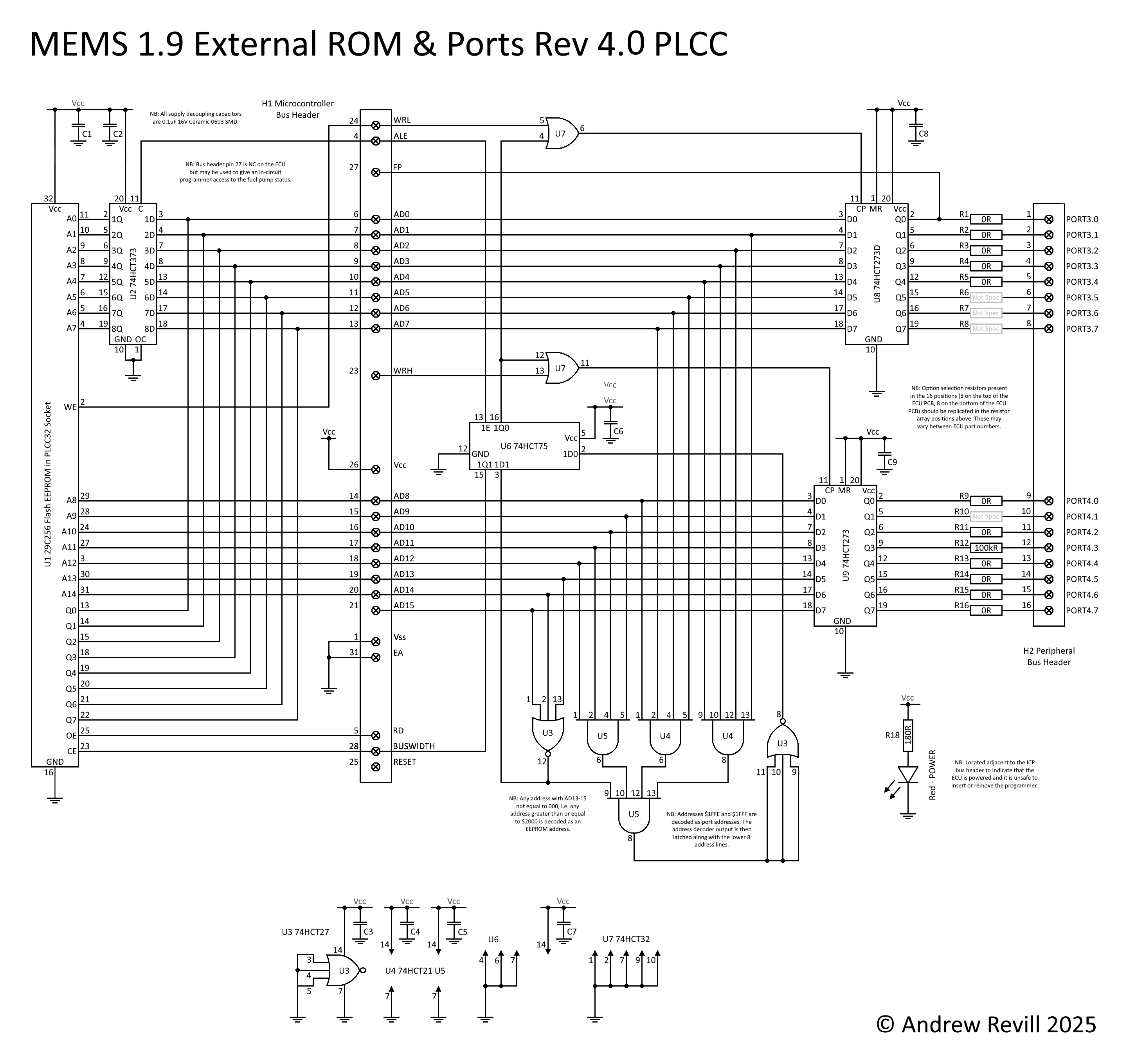
The latest modules switch from 74LS/74ALS through-hole integrated circuits to 74HCT surface-mount exclusively, except for the EEPROM chip which switches from a DIP format in a ZIF socket to a smaller PLCC package. As these EEPROM chips are basically obsolete (but still easily obtainable in bulk from specialist surplus stockists), the PCB manufacturer is unable to supply the PCB with the ROM mounted, so instead I get the boards assembled with a PLCC32 socket and just plug the chips in myself.
The other main changes are around the address and enable decoding logic, partly to simplify it, partly to enable me to work with readily available devices in the 74HCT family and partly to resolve some twisted glitches where data on the multiplexed data and address bus could be mistaken for addresses under some circumstances, trigger dummy ROM write cycles and crashing the ECU. There’s also some considerable simplification of the IO port logic; the original design allowed for the ports to be used for input as well as output, and had tristate logic and inversion of the reset state to match the microcontroller’s internal logic exactly as per the datasheet, however in practice (after testing and working through all of the MEMS 1.9 firmware code) I could see that all that was needed was a basic output capability (interestingly, not quite true for MEMS 1.6 where the firmware does not keep a local copy of the state of the ports, so needs to be able to read back what it last wrote when toggling bits).
Along the way I’ve had to teach myself to use EDA/CAD tools. The above circuit diagram was converted into an EasyEDA schematic …
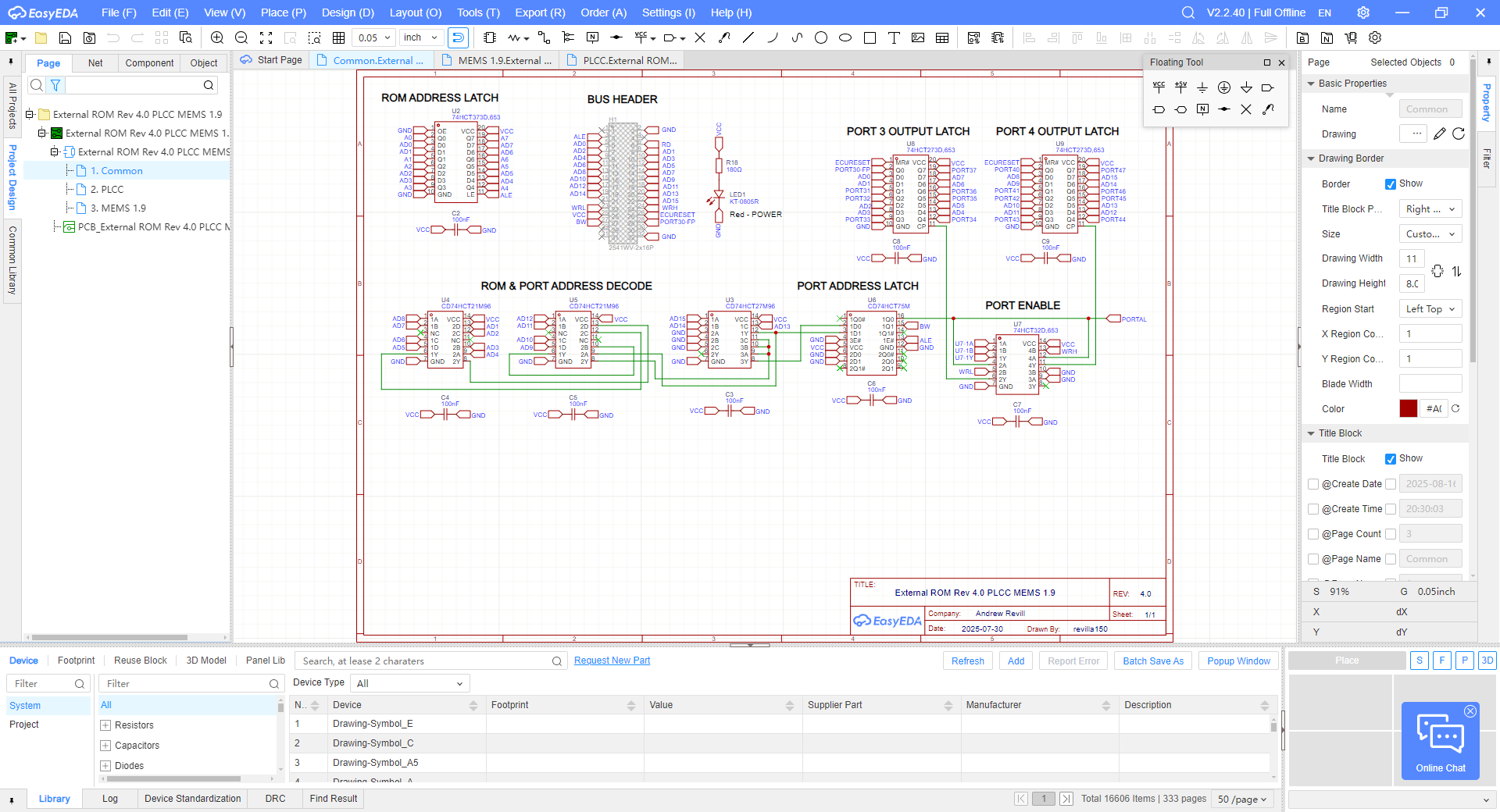
Then a PCB design …
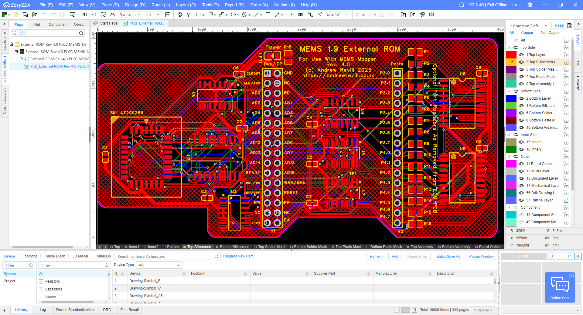
Which was finally manufactured for me by JLCPCB.
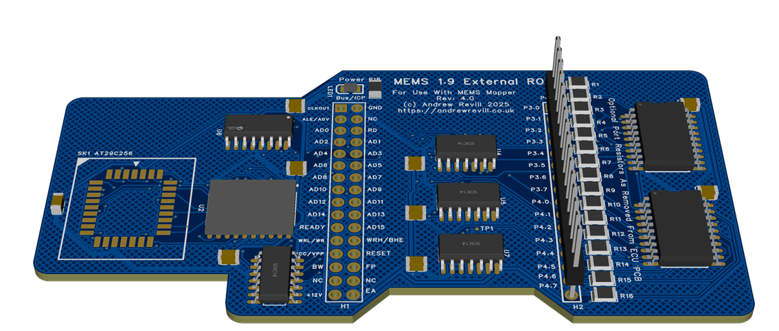
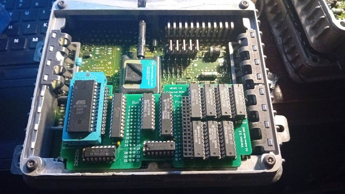
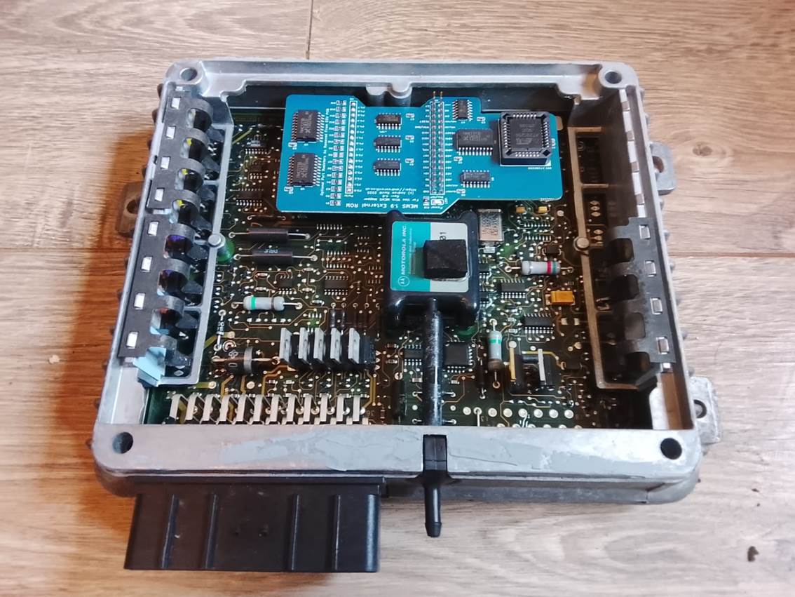
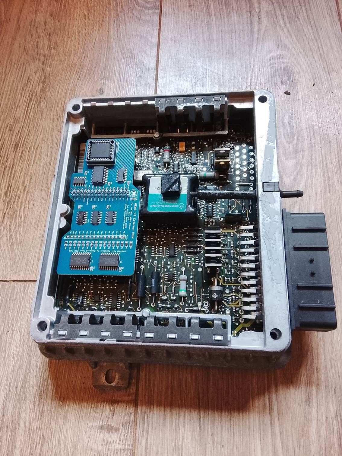
The finished board fits neatly inside the case of the MEMS 1.9:
Installation is not entirely straightforward. The MEMS 1.9 has pads for the necessary bus headers on both the MCU bus and port side on the PCB. These are generally connected together using 0Ω resistors (shorting links with the form factor of an SMD resistor, allowing them to be optionally placed by pick-and-place machines during manufacture). The silicone conformal coating needs to be stripped around these header pads, which are then cleared of solder using an electric desoldering pump.
It is then necessary to remove any optional resistors connecting the MCU bus lines to the ports from the PCB. These resistors are arranges in two rows of 8 resistors, one row on top of the board:
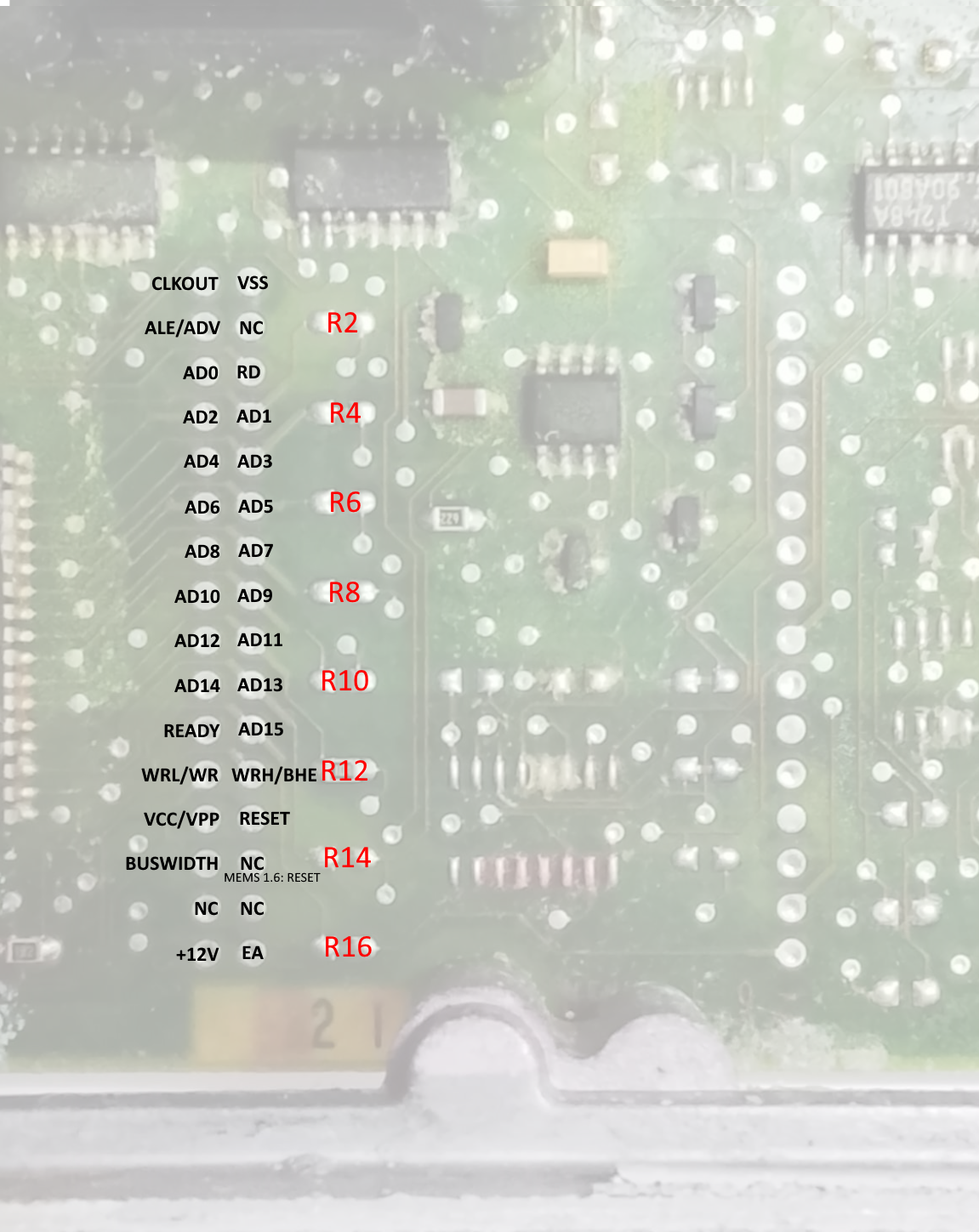
And one row on the bottom of the board:
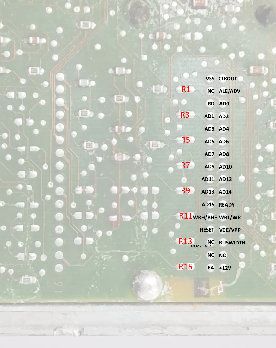
It is necessary to make a careful note of which of the 16 resistors were and were not installed; this pattern needs to be replicated on The remap board itself which has a row of 16 sets of resistor pads labelled R1 to R16. There are only around 4 different combinations of options installed corresponding to 4 basic hardware configurations of the ECU, with all of the different part numbers then being different software configurations on these basic hardware configurations. I’ve had the boards manufactured with the most common set of options resistors installed, but for example MGF ECUs will have additional options installed to support the engine bay temperature sensor and fans and these need to be configured on the remap board by installing the missing resistors. I’ve made sure that the pads on the remap board match resistors of the same size as those used on the ECU PCB, so the existing resistors can simply be desoldered form the ECU PCB and soldered onto the remap board.
Note that R12 forms part of the Main Relay latching circuit as has a resistance of 100kΩ, not 0Ω like all of the others. I have had the remap boards manufactured with this 100kΩ resistor already installed as it is require din all ECUs.
Note also that on later ECUs, some of the 0Ω resistors were omitted and the PCB was modified to include small shorting link tracks straight across the resistor pads. In these cases, as there is no resistor to remove, the shorting links need to be cut. This is a delicate operation as the PCB is 4 layers deep and there are other copper traces below these shorting links which must not be damaged. After trying many different techniques (scraping with a scalpel, ablating with a low-voltage, high-current “short killer”, a Dremel with an end-mill bit in a drill press) I found the best method is to use a pencil-sized hand-held micro drill fitted with a tiny diamond grinding burr. Set on high speed, you can use this almost like a rubber to just progressively erase the copper track. With care and quite a bit of practice, it is possible to keep going until there is a clear break in the track without going any deeper into the board to affect the lower layers. I’ve got this technique down to the point where I can now reliably modify boards.
Once the header pads have been prepared and the existing option resistors have been removed and transposed across onto the remap board, the board can be installed into the ECU.
A Samtec EW-20-11-F-D-531 board-stacking header is used to mount the remap board onto the main bus headers (the one show in the picture is the 2 x 10, 20-pin version, the one used in the ECU is the 2 x 16, 32-pin version in the same series):
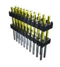
This must be mounted with the short ends down into the ECU PCB and the gold-plated long ends passing upwards through the remap board. These long tails form the connector for the ICP (In-Circuit Programmer) module which I will describe below. You need to be careful not allow solder to wick or wipe up these pins when soldering the remap board into place or then will not work as header connector pins. The short ends are very short, and only come flush with the surface of the underside of the ECU PCB. They require care during soldering. The holes in the ECU PCB are plated through, but you need to ensure that solder flows into the hole around each pin, without bridging adjacent pads. Care also needs to be taken with the GND pin which is connected to a ground plane later on both PCBs and tends to drain heat from the soldering iron. The pads for these pins can be very difficult to clear with the electric desoldering pump and can be difficult to solder satisfactorily. It is necessary to ensure that heat is applied to the joint for a little longer than normal to ensure that the PCB pads are sufficiently hot to form a good tinned joint.
The other single-row port header uses a regular 19mm length 0.1”, 16-pin header strip. The best sequence to follow is:
- Solder the double-row header to the ECU PCB.
- Sit the single-row header loosely in place.
- Place the remap board onto both headers. This ensures that the two headers are accurately spaced and parallel and that the remap board is level (or at least at the correct angle to allow soldering of both headers).
- Tack two corner terminals of the double-row header on the top of the remap board.
- Tack the end terminals of the single-row header both on the top of the remap board and the bottom of the ECU. Make sure everything is aligned and nothing is stressed.
- Solder everything up properly.
Be warned that once soldered into position, it is very difficult, in fact almost impossible, to access the inner sides of the header joints or to remove the remap board without damaging the ECU PCB. There are 96 soldered joints in total, the holes will not clear of solder with the pins in place and you cannot melt all 48 pins on either board at the same time. So it is critical to get everything right the first time.
Because of the difficulties involved in installing the
board, the amount of time it has taken me to work out a way of doing it right
every time, and the potential to ruin the ECU if the procedures are not
followed exactly, I would prefer to supply converted ECUs or to convert ECUs
for people, rather than selling the conversion parts as I do for MEMS 2J ECUs.
I cannot accept any responsibility for any ECU that does not work properly if
someone has insisted on buying a parts kit from me to upgrade their own ECU.
Neither is it likely that I would be able to fix up an ECU that was converted
incorrectly. If I convert an ECU for someone it will work; and if it does not,
because of what I have done, I will replace it. If you really want to have a go
at doing your own, you accept all responsibility for the outcome!
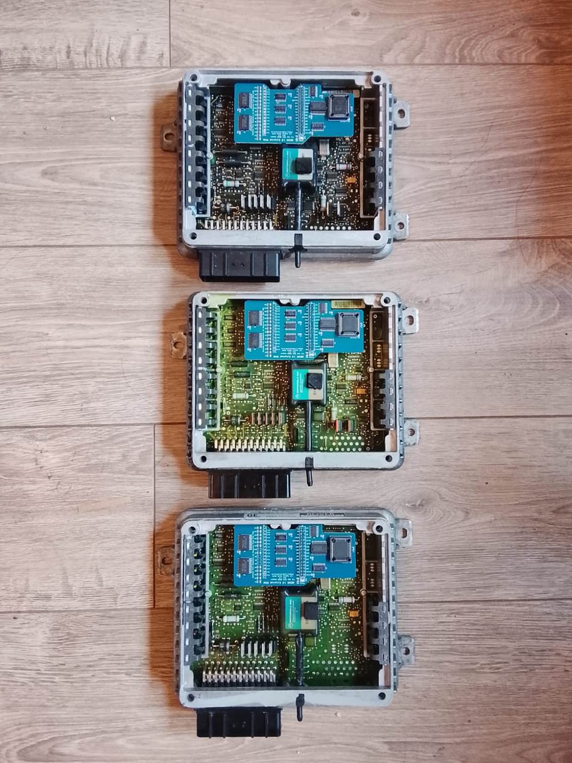
I have quite a production line running here!
Map
Switching Resistors
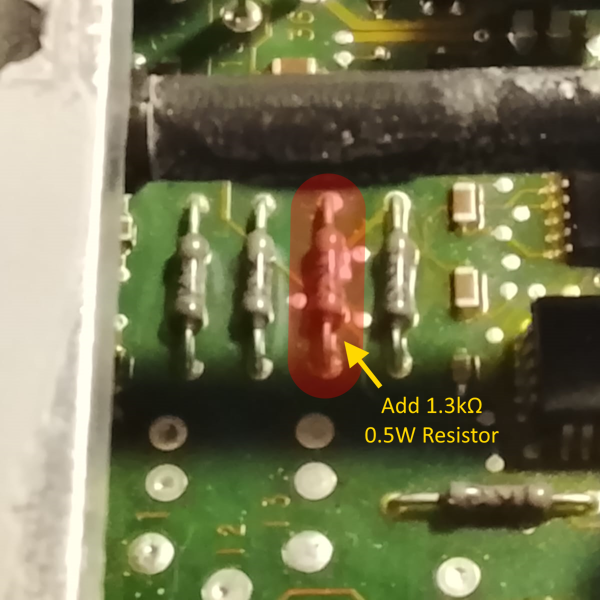
Once feature I have ported across from MEMS3 to MEMS 1.9 is the ability have two maps and to switch between maps with the engine running. The MEMS 1.9 is however very challenged in terms of unused input pins which may be used as map switch inputs. I have provided options to allow the immobiliser signal pin to be used (if you chose to apply the Firmware Immobiliser Delete wizard built into Mapper), or to allow you to select the alternate map by placing your foot on the accelerator when first turning on the ignition. However, for MANUAL cars, the most convenient input is the unused AUTO GEARBOX park/neutral switch pin; the problem is that there are a coupe of resistors missing (and one with a wrong value, just used to turn the input off) on the manual gearbox ECUs which need to be installed to make this input functional.
It is easiest to do these whilst the ECU is in pieces for conversion to remappable.
- This resistor will
normally be missing in a manual gearbox ECU. The PCB holes should be
cleared of solder using a heated desoldering pump and a 1.3kΩ 0.5W
through-hole resistor should be soldered into the position shown.
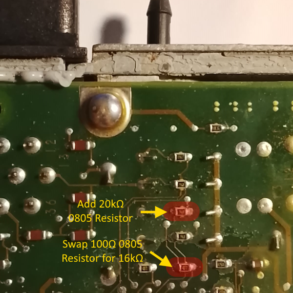
- The 20kΩ 0805 SMD resistor shown here will also normally be missing (if present it will be 19.6kΩ but 20kΩ is close enough and easier to obtain) and should be soldered into place.
- The 16kΩ 0805 SMD
resistor shown will normally have a 100Ω resistor in its place (again
if the 20kΩ resistor above is present, this resistor will be
17kΩ but 16kΩ is close enough and easier to obtain). This should
be removed and a 16kΩ resistor should be soldered into the position
instead.
Mapper
Support for MEMS 1.9
MEMS Mapper was originally (called MEMS3 Mapper and) built for the MEMS3 EU3 architecture. This was expanded to cover Chinese MEMS3 EU4 architecture, which required a separate build of MEMS Mapper as it s memory map was quite different (4Mbit EEPROM instead of 2Mbit). Later it was expanded to cover MEMS 2J and the Land Rover Td5 MSB by introducing another separate EU2 build.
MEMS 1.9 was just a stretch too far to call it just another memory map for a MEMS3. Although a lot of features are similar (MEMS3 and 2J are clearly evolutions of the earlier designs), a lot was very different:
- The processor is an Intel AN87C196KD instead of a Motorola MC68336 or 68332.
- The processor is natively 8-bit rather than 16/32-bit.
- Word or longer data is stored in Little-Endian format (low order byte first) rather than Big-Endian (high order byte first).
- All tables are in 8-bit format, using Byte data rather than Word data.
- There is no separation of boot loader and firmware, and the map data lives in one monolithic space with the firmware.
So a different approach was needed.
When reading a MEMS 1.9 ECU in Mapper, or when opening a MEMS 1.9 binary file, the data is translated into a “pseudo-MEMS3” project. Obviously it could never run a MEMS3, but the data is reorganised to have the same structure as a MEMS3 project. Everything is moved to location where it would be found in a MEMS3. The firmware is written to the MEMS3 firmware address range. The map is written to the standard MEMS3 map address range. Where necessary 8-bit data is converted into a 16-bit format. This means that all tables are converted from 8-bit to 16-bit representation.
When writing a Mapper project to a MEMS 1.9 ECU, or when saving to a MEMS 1.9 binary file, the reverse translation takes place.
- THE TRANSLATION IS LOSSLESS AND EXACT. IF YOU READ A MEMS 1.9 AND WRITE IT BACK, THE ECU WILL BE BYTE-FOR-BYTE IDENTICAL TO HOW IT WAS BEFORE.
- IF YOU OPEN A MEMS 1.9 FILE AND SAVE IT BACK AGAIN IN MEMS 1.9 FORMAT, THE FILE WILL BE BYTE-FOR-BYTE IDENTICAL.
- IF YOU READ AN ECU AND EDIT THE MAP, THEN WRITE IT BACK, THE ONLY CHANGES WILL BE FAITHFUL REPRESENTATIONS OF THE MAP CHANGES YOU MADE.
- IF YOU OPEN A FILE AND EDIT THE MAP, THEN SAVE IT BACK, THE ONLY CHANGES WILL BE FAITHFUL REPRESENTATIONS OF THE MAP CHANGES YOU MADE.
This does have a few consequences:
- The project in Mapper is not an exact faithful binary representation of the contents of the ECU. If you’re just editing scalars and tables, this doesn’t need to concern you. If you try working directly on the binary, it can get confusing. The MEMS3 project spaces becomes a complicate mosaic of big-endian and little-endian integers. Some addresses in the Hex tab are shown as 6-digit hexadecimal MEMS3 addresses. Some, which are used to store the contents of the MEMS 1.9 ROM, are shown as the corresponding 4-digit MEMS 1.9 addresses. Integer values withing the MEMS3 project metadata will be big-endian as expected by Mapper, but scalars larger than Byte sized will be little-endian as expected by the ECU. MEMS Mapper understands how to decode all of these different areas and decoded numbers will be shown correctly in all cases. Scalars will show as their correct values according to the ECU’s native encoding. If you stick to the higher-level user interface, everything will be intuitive. However, if you do decide to dive into the binary directly, you need to be very careful to ensure that you understand exactly what you are editing.
- When Mapper applies firmware patches, it is patching firmware that is relocated to a different address space to that for which it was written. Jumps to absolute addresses will not be to the address specified in the code, as the code will not be in its normal absolute location. Again, MEMS Mapper understands all of this and is able to translate addresses backwards and forwards as required in all cases. So it is still able to patch firmware code that includes absolute addresses correctly.
- MEMS 1.9 8-bit scalars and tables use some odd scalings in order to maximise the resolution of the 8-bit representation. For example, RPMs are stores as multiples of 25rpm. This means that an 8-bit table values can represent any value from 0rpm (0) to 6375rpm (255 = 255 * 25 = 6375). This means that for example a MEMS 1.9 table CANNOT REPRESENT AN ENGINE SPEED GREATER THAN 6375rpm. This is a fundamental limitation of the design. There are other similar limitations on other types of data. When editing tables in Mapper, it tries to prevent you from entering values which cannot be converted back into 8-bit format when writing to a MEMS 1.9 OR saving as a MEMS 1.9 file. If you do manage to bypass these protections e.g. by editing the binary data directly, you will see an error message when trying to write the file to an ECU or when trying to save the file in a binary format as there is SIMPLY NO WAY TO REPRESENT THESE VALUES using the encoding scheme employed by the ECU.
- Because of the reduced resolution of the 8-bit tables, sometimes the values you enter cannot be stored exactly but will be rounded to the nearest 8-bit integer in the underlying encoding. For engine speeds this means every value will be rounded to the nearest multiple of 25rpm. For MAPs and other pressures, the encodings are rather more obscure and you may see value entered rounded to the nearest multiple of something which results in unexpected decimal fractions. This is not a problem with Mapper. It’s not really a problem at all – it’s just the nature of limitations of the 8-bit design of the MEMS 1.9 ECU.
- MEMS 1.9 IS SUPPORTED BY THE EU3 BUILD OF MAPPER. This is slightly counter-intuitive as MEMS 1.9 was generally an EU2 ECU, but makes sense given the above. To work with MEMS 1.9, always launch Mapper EU3, as the MEMS 1.9 data will be converted to MEMS3 layout behind the scenes to work on it. The EU2 build of MEMS Mapper ONLY supports MEMS 2J and the Land Rover Td5 MSB ECUs and will not allow you to open MEMS 1.9 projects or read MEMS 1.9 ECUs.
MEMS
1.9 Firmware & Map Library
I recently had the pleasure of meeting up with Ronnie Gibson. Ronnie led the department in MG Rover that was responsible for the design and manufacture of the earlier MEMS ECUs (prior to MEMS3). Ronnie is a Caterham 21 SuperSport owner and the ECU on his car failed. He had heard that I had some “recreated” SuperSport ECUs for sale and approached me to see if I could supply a replacement, which I did. Ronnie was able to help me with an awful lot of ex-factory data and insights. He also put a lot of effort into sorting out all of the ECU files that we had between us with lookups into tables and spreadsheets to identify what each one was. The files included full firmware and map dumps as well as PETA transfer files, which gave me the factory named and definitions for the various scalars and tables in each map.
I subsequently went through all of the files, putting together complete matching sets wherever we had corresponding files. I was then able to automate the disassembly of the firmwares, and I wrote a code correlator (similar to the one I developed for MEMS 2J and MEMS3, but operating on the earlier Intel code rather than the later Motorola code). The code correlator was able to identify corresponding code addresses, variables, tables and scalars in all firmwares, and means that PETA definition data can now be associated with table and scalar CLASSES across all firmwares; we therefore have almost perfectly complete PETA definitions even for the firmwares where we don’t have PETA files (that’s something PETA could not do).
This was all then fed to code I wrote to merge all of the correlation data and PETA definitions to update the definition files in Mapper.
The result is I now have a fairly complete library for MEMS 1.9 and MEMS 1.6, as well as pretty much full support for all of MEMS 1.9 and MEMS 1.6 in Mapper. I’ve combined all of that with the latest MEMS 3 and 2J and Land Rover Td5 data which I have and put the full library on the web:
- The full library is here: https://andrewrevill.co.uk/MapFirmwareLibrary/
- Most of the identified MEMS 1.9 files are here: https://andrewrevill.co.uk/MapFirmwareLibrary/Rover%20MEMS%201.9/
- These include the Caterham RoadSport and SuperSport special files.
- They also include the MGF files which were also used on the Lotus Elise (and often on Caterhams too).
- They also include many Rover T-Series files. These engines are still found in many classic Morgans.
- Most of the identified MEMS 1.6 files are here: https://andrewrevill.co.uk/MapFirmwareLibrary/Rover%20MEMS%201.6/
- These include the Caterham SuperSprint 1400 (EU1?) files.
- There’s a complete archive of all of the firmware support files across all MEMS generations here: https://andrewrevill.co.uk/MapFirmwareLibrary/Firmware%20Archive/
- e.g. for MEMS 1.9 here: https://andrewrevill.co.uk/MapFirmwareLibrary/Firmware%20Archive/Rover%20MEMS%201.9/ you will find all of the known firmware files in .HEX (raw binary) format, each one coupled with a .ASM (disassembly in text format) and either .XF1 or .XF3 (PETA transfer definition file).
- The library also covers the L Series Di (Dragonfly) diesel ECUs which are now fully support in Mapper. I don’t think there’s a lot of demand for these but in the spirit of preserving everything I can for future reference I included them.
This is probably the last remaining major dump of MG Rover data in existence, so I wanted to make sure it was captured, sorted, organised, preserved and made available on the web. I’m still desperately trying to locate the same data for the Land Rover Td5 ECUs. It definitely existed, but was last seen in a locked store cupboard at Gaydon. I fear it is no more. If anyone reading this knows of any Land Rover Td5 PETA data please do get in touch with me. I already have all of the firmwares and maps, but it’s the definition data which is missing, and that is key to understanding much of it.
Very many thanks Ronnie for all of your help! (I have Ronnie’s permission to mention his name and involvement here).
Programming
the Modified MEMS 1.9 ECU
The MEMS 1.9 ECU does not support normal OBDII communications. Unlike MEMS 2J and MEMS 3 it does not support ISO1941, ISO14230 (KWP2000) or Rover BMW protocols as it predates these standards. It also does not have a separate boot loader and firmware architecture, which is necessary to allow programming of the firmware (you need something that remains and lets you communicate and program the firmware after the old firmware is deleted). The ECU was never designed to be programmable, so it doesn’t have any of the programming support added to the later ECUs (MEMS3 was programmable; MEMS 2J was originally designed to be programmable but released in non-programmable form to save costs). There are basically two ways that a MEMS 1.9 ECU, modified as described above, can be programmed with new firmware and map.
- By programming the EEPROM
chip on the bench.
This is how I programmed the devices during development, but it’s not recommended for production ECUs. The development devices had Zero Insertion Force sockets, mostly in DIP format, that were OK for multiple insertions and removal of the chips. The production devices have PLCC44 sockets that grip the chips firmly and are really not deigned for repetitive operations. It is also difficult to support the installed PCB securely enough when pressing the chips into place and bending the PCB may lead to damage. It is still possible however, and if you want to reprogram one of these ECUs with a fixed map as a one-off then it may be a practical solution. For completeness I will describe it below. - Using an In Circuit
Programmer device.
This is how I would recommend programming production ECUs. I will cover it in detail below.
Programming
the EEPROM Chip on the Bench
The remap board contains an AT29C256, 256 kBit, 32 kByte EEPROM. Production devices so far use the PLCC44 version of this chip but I have parallel designs using the DIP packaged chip. These chips match the size of the internal ROM in the microcontroller. They are obsolete devices, but still readily available from obsolete silicon stockists. Because of this, I cannot have the PCBs manufactured with the EEPROM chips installed. I therefore have them manufactured with sockets (normally PLCC but could be DIP) and plug the chips in myself. It is perfectly possible to physically remove the chip from its socket, program it in a bench programmer, and plug it back in.
If doing this, however, there are a couple of things you need to be aware of:
- The memory address map of
the chip is slightly “mangled”.
The microcontroller mounts the chip at base address 0x2000. It is of size 0x8000 so covers the address range 0x2000-0x9FFF. This is rather awkward to decode, as there is no unique set of upper address line states which corresponds to a ROM address. There is however a shortcut that can be taken. My logic decodes ALL addresses above 0x2000 as EEPROM addresses (there is nothing else at higher addresses on the external bus). So any binary address where any one of the 3 higher address lines is a 1 is decoded to select the EEPROM (binary addresses 001XXXXX to 111XXXXX, or hexadecimal 0x2000 to 0xFFFF. Then the upper address lines A15 is ignored. This means that bus addresses 0x2000-0x7FFF map to EEPROM addresses 0x2000-0x7FFF, and bus addresses 0x8000-0x9FFF map to EEPROM addresses 0x0000-0x1FFF.
The upper 8kB of the EEPROM space is therefore stored at the bottom of the chip, followed by the lower 24kB.
This makes no difference during normal operation, and when programming through the In Circuit Programmer as described below, as the same transformations occur when both reading and writing. If, however, you chose to write the chip in a bench programmer, you need to rearrange the data before writing as the programmer will not apply this transformation.
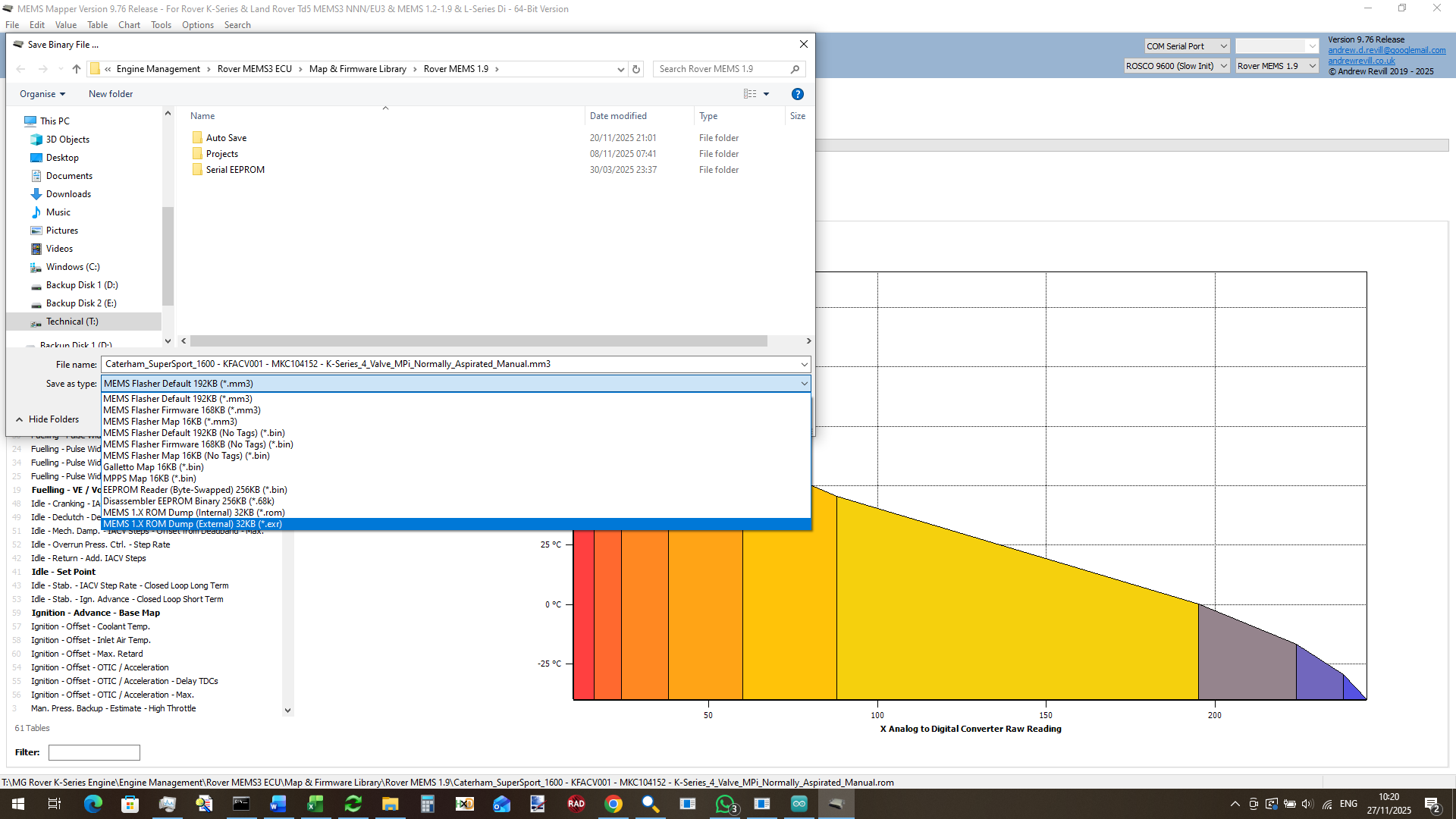
MEMS Mapper has support for this built in. You can save a MEMS 1.9 project as either a .ROM file (a normal, non-mangled binary ROM image) or as .EXR file (External ROM, a binary image with the above transformation already applied). You can use bench programmer to write the .EXR format to an AT29C256 chip and plug it in and everything will work. Do NOT write a stock MEMS 1.9 ROM image to an AT29C256 and expect the ECU to run, as I will see the code and data as being hopelessly rearranged.
- At address 0x2018 lives the CCR (Chip Configuration Register). This controls some of the basic operations of the chip, including configuring the address strobe scheme to be used on the external memory bus. When used with externa ROM on the remap board, this register needs to have a different value (0x3B – to generate WRL# and WRH# strobed) to that used by default with the internal ROM (0x3F – to generate BHE# and WR# strobes). Again , MEMS Mapper will correct this byte when either writing to the ECU through the In Circuit Programmer (sets to 0x3B), saving a .ROM file (sets of 0x3F) or saving a .EXR file (sets to 0x3B). So again you can use bench programmer to write the .EXR format to an AT29C256 chip and plug it in and everything will work as expected.
In either PLCC or DIP form, the AT29C256 chip can be programmed on the bench using an XGecu T56 or T76 USB programmer.
Programming
Using an In Circuit Programmer
For repeated programming of the ECU, during development or at e.g. a rolling road mapping session, repeatedly removing the chip to reprogram on the bench is not a practical solution. I have therefore developed an In Circuit Programmer which works alongside the remap board.
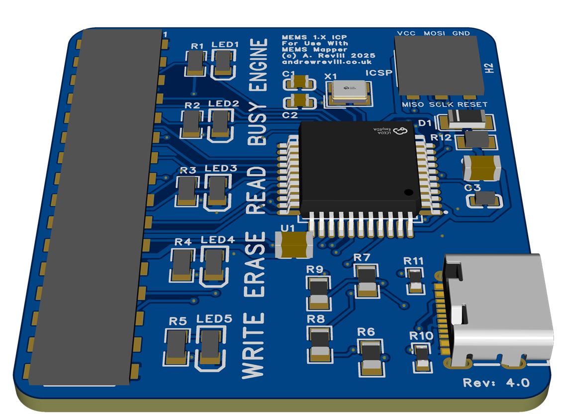
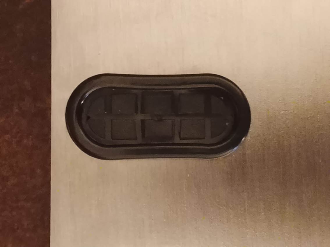
This plugs onto the top of the main bus header on the remap board and connects to a PC via a USB-C cable. I produce a new laser-cut lid for the ECU that has an oval port aligned with the bus header which allows the ICP to be plugged into a full assembled ECU. A rubber blanking grommet is supplied which seals the hole when the ICP is not connected.
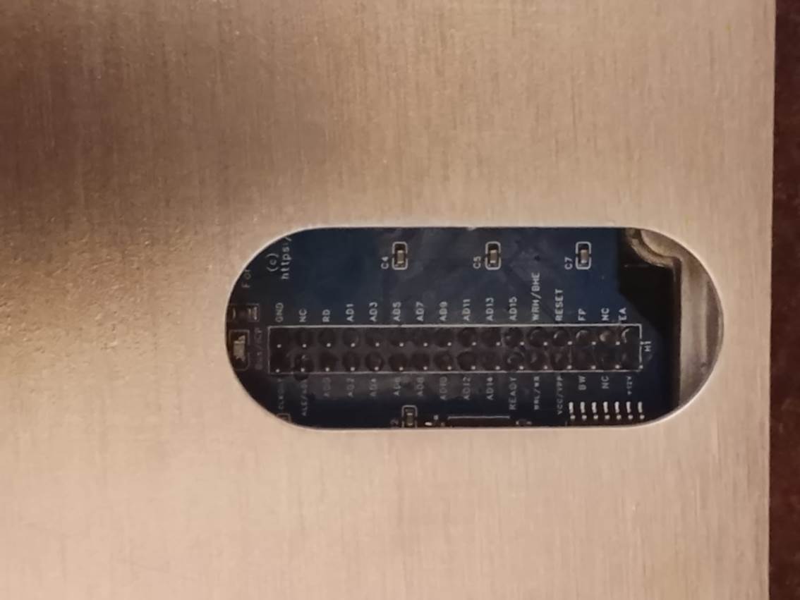

The ICP can remain plugged into the ECU when running the engine. This means that for a rolling road session the ICP only needs to be plugged in once and can be left connected to the laptop across multiple roller runs.
The ICP works by forcing the main ECU microcontroller into a RESET condition. In RESET it releases control of the external memory bus, and the ICP takes control of the bus and then talks to the memory chip in the same way the main microcontroller would. It is very much the electronic equivalent of removing the memory chip and programming on the bench, but instead of physically removing the chip, it is electronically isolated instead. This does mean that you cannot read or write the ECU with the engine running, however this is not a big restriction and the device is interlocked to prevent this causing any problems. As the remap board is managing the external IO ports, it is aware of when the fuel pump is turned on. It will not allow the ICP to attempts to take control of the bus when the fuel pump is turned on, as this means the engine is potentially running.
There’s a bright red LED adjacent to the bus header on the remap board. This indicates that the ECU is powered up. To avoid possible damage to the ICP, you should not plug the ICP in or remove it when the ECU is powered. The ECU will normally shut itself down a short while after the ignition is turned off. You can force the ECU into a non-powered state by disconnecting the battery or master cutoff switch, or briefly pulling the ECU fuse. On the ICP bord itself are several coloured LED, each one labelled. These LEDs indicate:
- ENGINE (RED) – The engine is potentially running (the fuel pump is turned on) and so the ICP is locked out.
- BUSY (BLUE) – The ICP has taken control of the ECU memory bus. You will not be able to start the engine.
- READ (GREEN) – The ICP is reading the EEPROM contents.
- ERASE (YELLOW) – The ICP is erasing the EEPROM contents.
- WRITE (WHITE) – The ICP is writing to the EEPROM chip.
In MEMS Mapper, you can READ either a stock or modified MEMS 1.9 over the regular OBDII connection. You can only WRITE to a modified MEMS 1.9 using the ICP. Although you can still read a modified ECU the regular, reding via the ICP is much faster. A full read or write typically takes between 4 and 8 seconds (compared to several minutes to read over the regular OBDII connection). The file you will get from reading the ECU over OBDII or via the ICP will be identical.
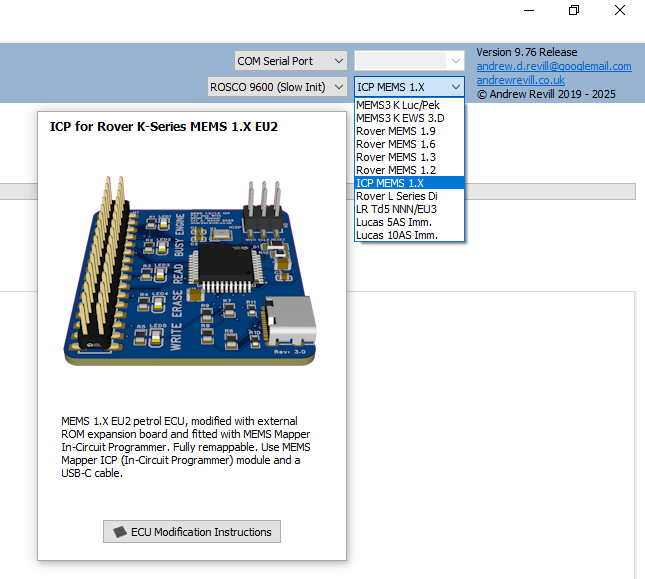
To write to a modified MEMS 1.9 ECU using the ICP, you must select ICP MEMS 1.X as the ECU type in MEMS Mapper. Select the COM port which corresponds to the USB-C cable in the normal way, then write to the ECU just as you would to a MEMS3.
For anything else, such as the installation of custom firmware patches, you must select the correct ECU type Rover MEMS 1.9 again. This ensures that MEMS Mapper knows what kind of ECU the file belongs to (MEMS 1.9 / 1.6 / 1.3 / 1.2 files are all the same basic structure) and patches it accordingly. You can however edit tables and scalars with the ICP MEMS 1.X selected, as tis works identically across all of the MEMS 1.X ECUs. Options which cannot be used with ICP MEMS 1.X selected will be disabled or invisible on the menus until you select the correct ECU type.
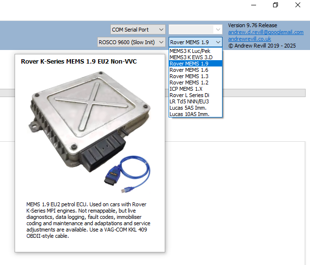
To read from a modified MEMS 1.9 ECU using the ICP, select ICP MEMS 1.X as above. To read from either a stock or modified MEMS 1.9 ECU over OBDII, select Rover MEMS 1.9.
Other than the need to select the correct device as described, reading and writing the ECU is then exactly as for MEMS 3 or 2J.
Using
MEMS Mapper with Modified MEMS3 ECUs
In additional to the normal maintenance features provided by MEMS Mapper even with stock MEMS 1.9 ECUs, the following are support with modified remappable ECUs:
- Read / Write / Verify / Erase Firmware & Map
- Note that as the ICP does not rely on the ECU having a viable boot loader, it is not possible to brick the ECU when writing.
- Dual Map Switches with Live Switching
- With a Selection of Available Inputs
- Throttle-Based Switch
- Immobiliser Delete (Firmware Method)
- Injector Swaps
- MAP Sensor Swaps
- Flywheel Trigger Pattern Swaps
Nearly
everything works pretty much the same as on MEMS. One small difference is that
in a MEMS 1.9 the map is at an arbitrary address within the same ROM address
space as the firmware; for this reason, the firmware and map cannot be read
from and written to the ECU separately as with MEMS3, but are always written
together as a single operation.
Immobiliser Delete
One request I often get is to delete the
immobiliser functionality on a MEMS 1.9. The MEMS 1.9 ECU does NOT have a flag
in the map to force it to run without a valid immobiliser signal, as found in
MEMS 3 and 2J maps. There is a crude workaround which involved editing the
serial EEPROM contents to put the ECU back into factory learning mode, but it
is then necessary to cut the wire from the immobiliser as if the ECU ever sees
a valid immobiliser code it will immediately learn it, lock to it and become immobilised
again. There are reports of this happening spuriously, even many years later,
when the ECU picks up noise on the cur input. It is therefore safest to ground
the ECU of the cut wire.
On MEMS 3 and MEMS 2J I provided a
“Firmware Immobiliser Delete” wizard. This modifies the firmware code to
effectively ignore the immobiliser status. When this is applied, the ECU will
still report itself as being immobilised over diagnostics, but this flag has
absolutely no effect and the ECU continues to run normally. I have replicated
this wizard for MEMS 1.9 ECUs. The gives a robust and permanent (but
reversible) method for deleting the immobiliser function of a MEMS 1.9. Because
it does not require the immobiliser connection to be cut and grounded, it has
the added advantage of leaving the immobilise code input pin available for use
a s a map switching input.
Read the ECU.
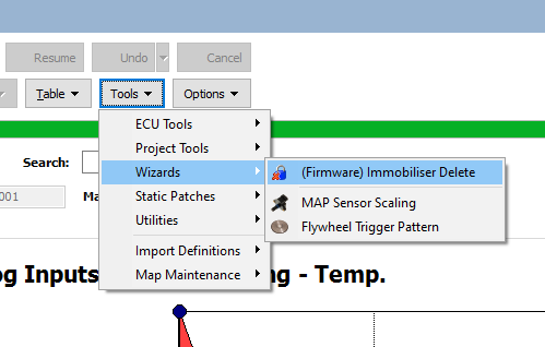
Click Tools | Wizards | (Firmware)
Immobiliser Delete from the menu.
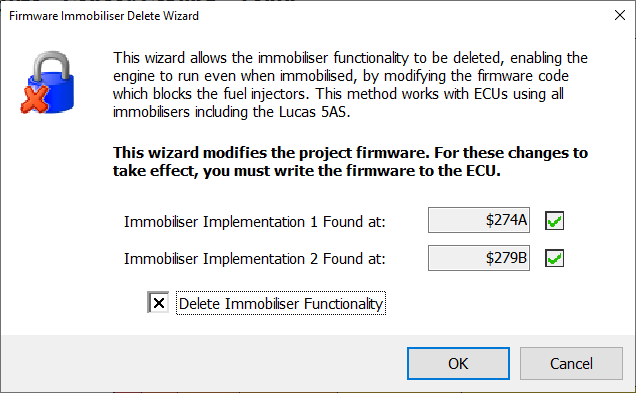
Check the Delete Immobiliser Functionality box and click OK.
Dual Map Switching Patches
Using MEMS Mapper EU3, Rover MEMS 1.9
ECUs can now be configured to switch between two separate maps. The switching
can be live with the engine running, even under load. The engine will not even
cough or hesitate when switching.
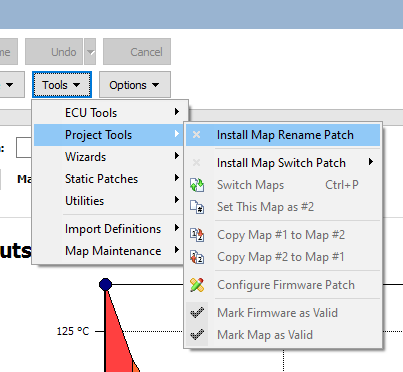
Select Tools | ECU Tools | Install Map
Switch Patch from the menu, then select which available input pin you want
to use.
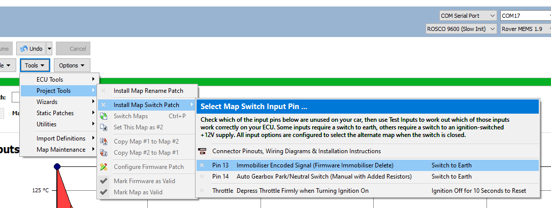
MEMS 1.9 ECUs do not have many spare
input pins available. Pin 13 is the immobiliser code input and may be used if
the immobiliser has been deleted in the firmware as described above. Pin 14 is
the automatic gearbox park/neutral switch and can be used on manual ECUs
provided that the resistor modifications described above have been complete.
There is also the option to select the alternate map by placing your foot
firmly on the accelerator when first powering the ECU on. For help with
identifying the relevant pins and how to wire a switch to each one, select Connector
Pinouts, Wiring Diagrams & Installation Instructions from the menu as
shown above. The help information is also available through the following link:
Dual
Map Memory Layouts
Many MEMS 1.9 ECUs do not have a single
block of free unused ROM space to hold a second map. Unfortunately about 50% of
firmwares have an additional (unknown) code block floating right in the middle
of the free space between the normal end of the firmware and the start of the
map, and the space either side of this code block (which cannot be relocated)
alone is not sufficient to store a map. But I realised I could be a bit
creative and the ECU firmware code would now know the difference …
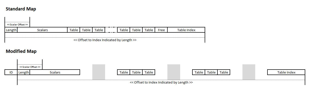
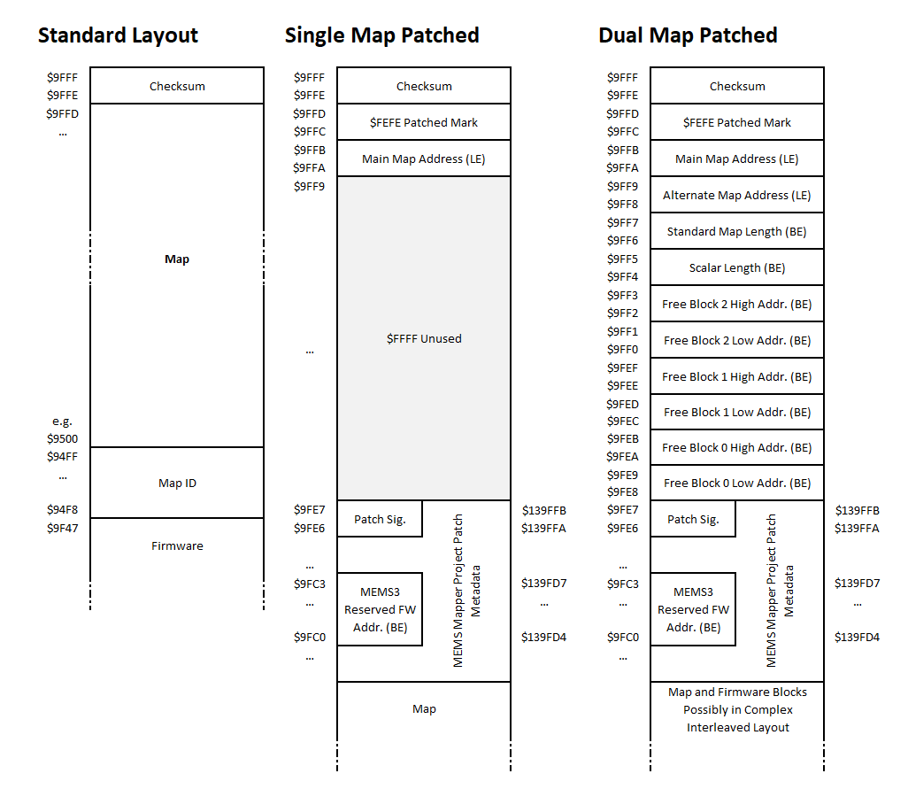
In simple terms, the standard map
structure consists of a length indicator, followed by the scalar data. This is
followed immediately by the table data blocks. There may then be a bit of free
space, then finally the table index. This contains pointers to the individual
table blocks. Scalars are found by adding an offset to the base address of the
map. Tables are found by adding the indicated map length to the base address of
the map to find the index, then subtracting an offset determined by the table number,
and then following the pointer to the table data.
It is possible to spread the contents of
the map over multiple free blocks withing the EEPROM as shown below. So long as
the length pointer then reflects the total offset from the base address of the
map to the end of the table index, all of the calculations will still work. The
scalars must be in once single block, so that the offset to each scalar from
the base of the map is preserved. The tables can be distributed across the free
blocks. The table index at the end must be in one block, and the length indicator
must indicate the total length to the end of the index. The index is updated
with the correct pointers to the table data blocks, wherever they are. Then
finding a table using the above logic will still work.
When Mapper is writing a file out in .ROM
pr .EXR format, or writing to a modified MEMS 1.9 ECU, it automatically adopts
one of the layouts shown below.
Where no firmware patch is applied the
Standard Layout is used. This ensures that a standard ROM is written out in a
byte-for-byte identical layout to that of the original standard ECU.
Where a firmware patch is applied which
only requires a single map, the map is written as a standard map, but is moved
down in the memory address space to allow Mapper to write patch metadata at the
top of the EEPROM above it. At address $9FFC a patched mark $FEFE is written.
This allows Mapper to recognise it as a patched layout when reading it back in
(this location would normally only ever contain $FFFF or a table pointer, $FEFE
can never be a valid table pointer as it points outside of the ROM address space).
The address at which the map is then written appears at $9FFA. There is then
some unused space (to allow the headers for the single map and dual map patched
layouts to align in memory) which is filled with $FFFF. This is followed by the
MEMS Mapper project metadata (exactly as it would be written to a MEMS3 ECU)
which allows MEMS Mapper to correctly uninstall the firmware patch if required.
Where a firmware patch is applied which
requires dual maps, things get a bit more complicated. Mapper analyses the ROM
space looking for large blocks of unused, consecutive blocks of $FF bytes. It
uses only the largest three blocks where multiple blocks are found (in any real
ECU it will normally find two blocks where the additional code block is not
present, or three blocks where it is present as the second block in the first
case is split into two). It records the addresses of both maps, the standard map
length, the length of the scalar block and the addresses of the free blocks in
the header as these are all require for patch decoding or uninstallation. It
then allocates each of the following in order from the remaining space in the
free blocks:
- Main
map scalars (as a single block).
- Alternate
map scalars (as a single block).
- Main
map tables (individually).
- Main
map table index.
- Alternate
map tables (individually).
- Alternate
map table index.
Whenever it tries to allocate anything
from a free block and finds that it does not fit, it closes the block to
further allocations (even if they would fit, to preserve the relative sequence
of map elements) and moves on to the next free block.
This technique results in a dual map
switch patch and two maps fitting into every MEMS 1.9 file that I have tested.
Notes on Map IDs
A standard MEMS 1.9 does not have
separate firmware and map IDs. It is built as one monolithic block and has a
single Software ID.
It is convenient to be able to rename
maps, as for MEMS 3 and MEMS 2J. Particularly for tuners who may have many
different maps to keep track of. It is also convenient to be able to see the
current map ID in live diagnostics where a dual map switch is installed, in
order to see that the correct map is being selected.
Editing the software ID in the file does
not provide a solution, firstly because MEMS Mapper would then lose track of
the firmware ID and would not be able to associated table and scalar
definitions correctly, and secondly because that would still only provide one
ID in a dual map switching setup.
MEMS Mapper allows you to edit the map ID
freely. This is stored in the MEMS3-format project data. This does not drive
the software ID subsequently reported by the ECU.
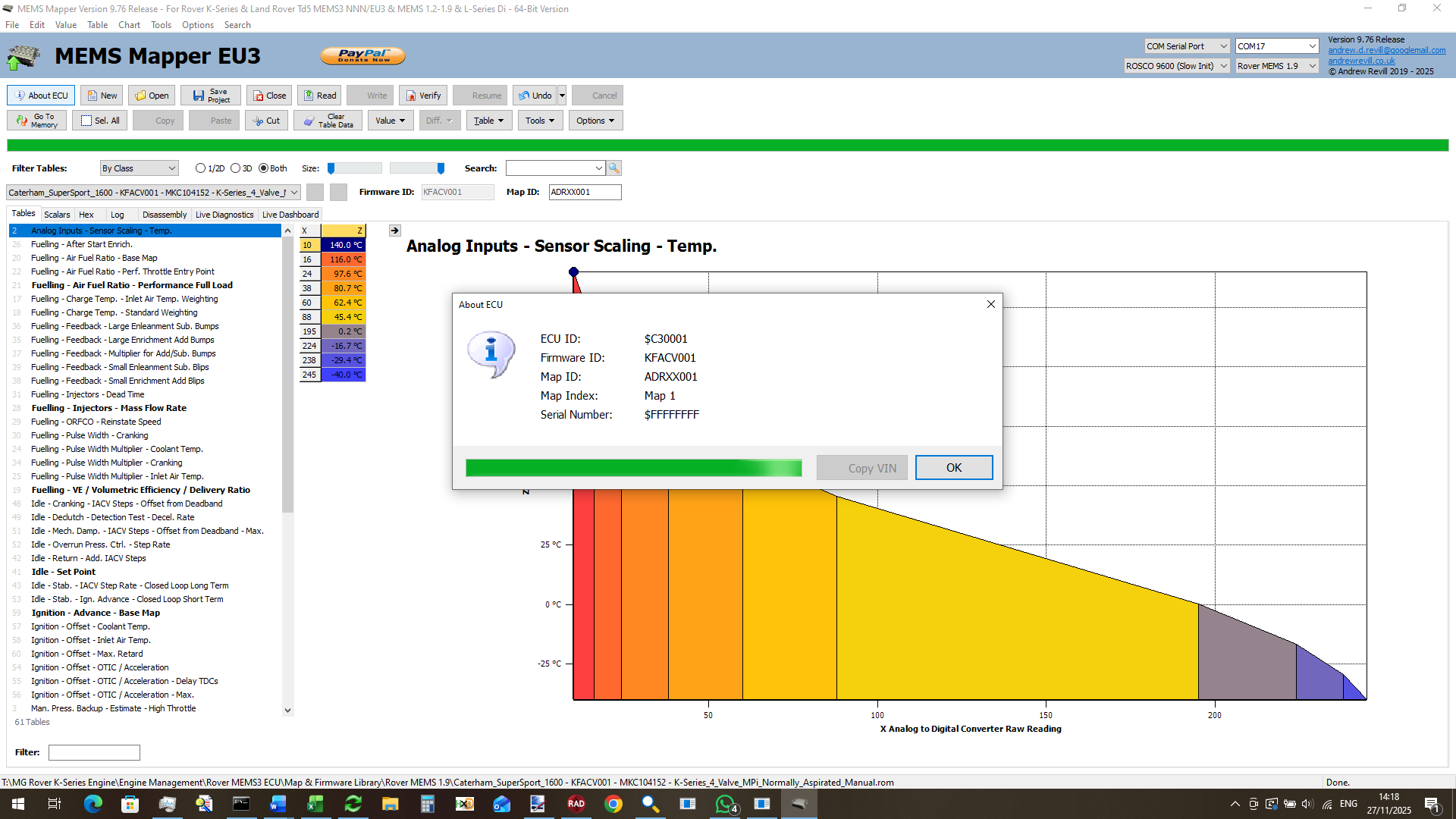
When a dual map patch is installed, MEMS
Mapper includes a map ID in the 8 bytes immediately preceding the standard map
data. It’s effectively adding an additional header to the map format. The map
switch patches include a firmware patch which causes the ECU to report this map
ID over live diagnostics. For dual map ECUs this solves the problem, and the
map IDs set in Mapper are then reported by the ECU over live diagnostics and in
the About ECU dialog box.
If you want to be able to edit the map
name and have the ECU report it correctly without having a dual map setup, I
have provided a Map Rename Patch. This includes only the minimum
firmware code patch extracted from the full map switch patch to allow the ECU
to report the edited map ID over live diagnostics and About ECU. When written
to the ECU, the file will then use the Single Map Patched format shown
above. Again the map will have an additional 8-byte Map ID header prepended.
In the screenshot below, you can see that
the original firmware ID was KFACV001 but the map was renamed as ADRXX001 and
this is reported correctly by the ECU.
Future Projects
With the completion of MEMS 1.9 support,
I now have practical remap solutions for all of the Rover MEMS ECUs from around
1994 right up until the Chinese EU4 ECUs of 2005.
MEMS Mapper now supports editing maps for
earlier ECUs included MEMS 1.6, MEMS 1.3, MEMS 1.2 and Rover L series Di
(Dragonfly).
I am in the process of adapting the MEMS 1.9 remap board for use in MEMS 1.6 ECUs. These are similar to MEMS 1.9, bit have some additional challenges. In particular, there is now port-side header provided on the ECU PCB and no clear separation of bus and IO ports using 0Ω resistors. This means that separation of bus and ports is a much more complicated job, probably requiring a custom daughter board for the main microcontroller to allow the pins to be broken out. There are also some code differences which require hardware changes. MEMS 1.9 keeps a shadow copy of each output port in a register. When it wants to changes one output bit, it toggles the bit in the register and then writes the whole register out again. The ports are therefore pure output. MEMS 1.6 does not do this; when it wants to change one output bit, it firstly reads the port to get the current state, toggles the bit and writes it back again (the early MEMS units were based on the AN87C1986KB/C not KD and were therefore even tighter on RAM, so the designs did not waste a byte where not absolutely necessary). This means that although the ports are purely for output, the MCU needs to be able to read them like inputs to see what it last wrote out.
I’m hopeful I can get the MEMS 1.6, non-turbo ECUs remappable.
MEMS 1.6 turbo maybe a very different matter. Because they needed more port lines for sequential injection, they already moved to external ROM and reconstructed ports using custom ASIC chips that do a lot of what my board does. It will either be a lot easier to do what I need to do (if those custom chips will allow me to work through them) or impossible (if they won’t).
This will take MEMS Mapper support back to around 1991, and will bring in support for cars like the SPi Mini and EU1 Caterham SuperSprint, as well as earlier T-Series cars.
I think that will be about as far back as I will go with proper remap support. MEMS 1.3 is constructed in a much more archaic way. It has lots of logic daughter boards, no usable expansion headers and has almost no room inside to install a remap board. I just don’t think there is now the demand to make it worthwhile trying to crack MEMS 1.3 or earlier at this stage. Earlier ECUs could still be remapped on a one-off basis by saving the Mapper projects as .ROM files and getting these programmed onto blank microcontrollers, as I did when recreating the Caterham SuperSport MEMS 1.9 ECU a while back.
Still, it’s all come a pretty long way from the original
objective, which was to support EU3 MEMS3 only, so that I could remap my own
Caterham!