Connector
Pinouts, Wiring Diagrams & Installation Instructions – Rover MEMS 1.9
Connector
Pinouts
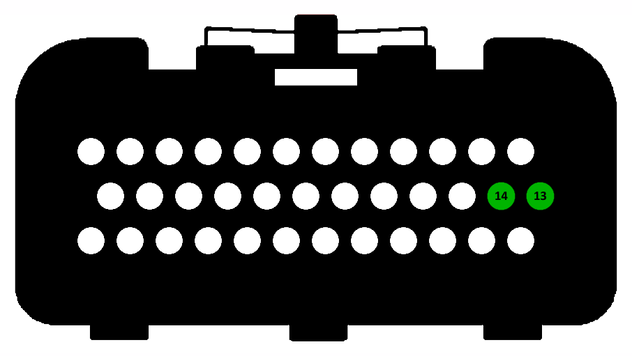
The connectors below are drawn viewed from the wiring side, i.e. looking at the connector housings when installed on the ECU. The pins used by the various map switches are highlighted. Use the diagram below to find possible map switch inputs which are available (not connected) on your ECU.
Wiring
Diagrams & Installation Instructions
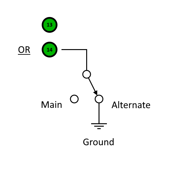
The diagrams and notes below show you how to wire up a map switch using the selected input pin.
|
Switch to Ground
Pins 13 and 14 are used with an ON/OFF switch to earth. A cable may be routed from the ECU pin to somewhere convenient, maybe behind the dash. Any type of latching (non-momentary) ON/OFF switch and any convenient earth point near to the switch may be used. |
|
Pin 13 is the Immobiliser Coded Signal input and may be used provided that the Firmware Immobiliser Delete wizard has been applied. The immobiliser may then be disconnected and the input pin may be connected to a switch to ground.
Pin 14 is the Gearbox Park/Neutral Switch input on an automatic gearbox ECU. It is usable as a map switch input on manual gearbox ECU, but may need some resistors adding or swapping as shown below to make the external input pin active. Again a simple switch to ground is required.
|
|
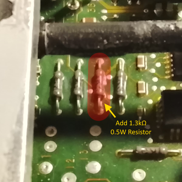
This resistor will normally be missing in a manual gearbox ECU. The PCB holes should be cleared of solder using a heated desoldering pump and a 1.3kΩ 0.5W through-hole resistor should be soldered into the position shown. |
|
|
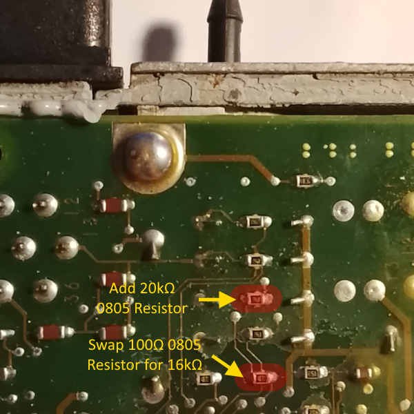
The 20kΩ 0805 SMD resistor shown here will also normally be missing in a manual gearbox ECU (if present it will be 19.6kΩ but 20kΩ is close enough and easier to obtain) and should be soldered into place. The 16kΩ 0805 SMD resistor shown will normally have a 100Ω resistor in its place (again if the 20kΩ resistor above is present, this resistor will be 17kΩ but 16kΩ is close enough and easier to obtain). If a 100Ω resistor is present, this should be removed and a 16kΩ resistor should be soldered into the position instead. |