MEMS3 Dual-Map – Live Map Switching
Download
Link: https://andrewrevill.co.uk/Downloads/MEMSTools.zip
Moving on from my previous experiments with injecting debugging code into the MEMS3, this is my first attempt to actually add new features to the ECU which are not present in the standard MG or Rover firmwares.
Using my MEMS Mapper application it
is now possible to add an alternate map to a MEMS3 and to switch between the
two maps whilst running.
This allows you to have “Track” and “Road” maps, “Performance” and “MOT” maps, “Pop & Crackle” and “Smooth & Quiet” maps or whatever you want. Personally I’ve taken a Kmaps base map, pushed some bits a bit further to make a really aggressive map for one, and then backed out a lot of their changes with tables and values from a standard MG ZR map for the other. This gives the option of a much softer, more relaxed drive for long distance touring or driving back from the office tired whilst still retaining the sharp sports drive the rest of the time. What you choose to do with it is up to you.
I’ve tried to write this article with the key information and examples that you need to learn to use the feature at the start and technical details afterwards. You can skip those if you don’t need to know how it works inside, although if you do decide to set this up on your own ECU I would recommend reading to the end before you start.
Highlights
The main highlight features:
· This seems to work well on almost any petrol MEMS3 ECU and any firmware version, and appears compatible with every MEMS3 I’ve ever seen in a Caterham (some Freelander, MG ZT and automatic ECUs do not have enough space remaining). I’ve tested it on a selection of ECU hardwares and with a wide range of different firmware versions, both VVC and non-VVC, automatic and manual, turbo and normally aspirated. The code as it stands will NOT work with TD5 diesel ECUs but could probably be adapted to do so if I can get hold of one to experiment with.
· It allows you to have two full completely separate maps on one ECU. It should work with any maps, standard MG Rover, Caterham, Z&F Tuning, Kmaps etc. You can mix and match any combination (provided that the two maps are built for the same firmware version). The whole map is duplicated, including tables and scalars. However, please refer to the section on Adaptations below.
· You can switch maps using just one extra wire from the ECU and one switch, or you can switch maps using the throttle with no wiring or switch required. If you are using a physical switch, three different ECU pins (Pin 21, Pin 47 and Pin 63) can be used as inputs. You add one extra pin into the ECU connector and a wire from this to a switch to earth. You can place the switch on the dashboard or wherever you like. See the section on Inputs below for more information. If you are switching using the throttle, all you need to do is put your foot on the throttle when you turn the ignition on to switch to the alternate map.
· If you are using a physical switch, you can switch maps whilst the engine is running without significant issues. It doesn’t miss a beat. The actual switching occurs at the start of the ECUs calculation cycle so is guaranteed not to happen in the middle of the ECU accessing the map. See the notes on Adaptations below.
· There are no physical modifications required to the ECU, no need to open it up, it’s all programmed through the OBDII port. It can all be reversed out at any time, and with the latest versions of MEMS Mapper supporting anti-brick write methods and having a bomb-proof bricked ECU recovery facility, there’s virtually no risk whatsoever of doing any damage.
· It’s still compatible with OBDII scanners and other tools. It doesn’t change the ECU’s communications in any way. Any OBDII scanner which reports calibration information will correctly report the details of the map currently switched in.
· It’s all done through my FREE MEMS Mapper application in a couple of clicks. You can use all of the features of the mapping application to edit either the main or alternate map and to switch between the two.
Step by Step Example
Below is a walk-through of a step by step, worked example. In this example I’m going to take an ECU with a stock MG ZR VVC 160 map and add a tuned map, allowing me to switch between the two.
You will need to download Version 5.78 or later of MEMS3 Tools from here: MEMSMapper.htm. An initial prototype (V1) was included in Version 5.00 but files created with that are not compatible with later versions (V2). Version 5.01 included the physical switch options but not the throttle option. Version 5.78 added the Pin 21 option.
We start by reading the ECU as usual (or opening a file we read and saved previously). If you’re not sure about how to do this, refer to MEMSMapper.htm.
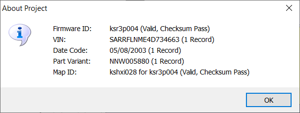
We will need to read both firmware and map. When complete it will show the firmware version (“ksr3p004” in this case) and the map ID (“kshxi028” in this case):
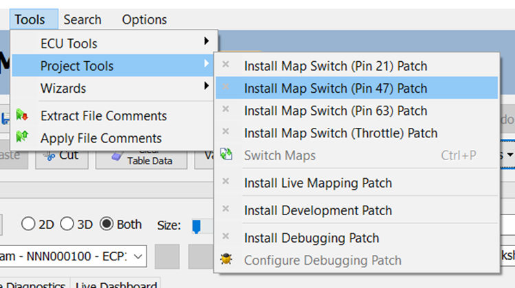
Next we will need to enable map switching for the project. In this case I’m going to use Pin 47 as the switch input pin, but see the section on Inputs below for more information. Check Enable Map Switching (Pin 47) under the Tools, Project Tools menu:
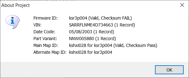
That’s it! We now have two maps in the project. A dialog box like the one below will be displayed, now showing details of the two maps.
So far the application will have done the following (in the project only – nothing is actually change don the ECU until you write the firmware and map back to it):
· Copied the existing map into spare, unused space in the firmware sector of the ECU’s EEPROM memory.
· Added some extra subroutines to the firmware to handle the switch input and the actual map switching.
· Identified the points in the firmware where:
o The power-on initialisation of the ECU is complete.
o The ECU is starting its main calculation loop.
o The ECU is reading the results table from its Analogue to Digital Converter (in the case of Pin 21, Pin 47 or Throttle only).
· Modified these points in the firmware to patch in calls to the new subroutines.
· Added some tags in the firmware sector to identify the patch applied, the addresses patched and the address of the additional map. These allow the patch to be removed in future if required.
MOST MEMS3 ECUs have enough spare firmware space to take one complete additional map. Below are the results of my investigations into some different versions. Where there is insufficient space, the tool will tell you so and will not make any changes. Note that although the sizes of tables within different maps for the same firmware can be different, the last thing in the map is the table index and that’s at a fixed address for any given firmware, so if one map will fit then all other maps compatible with that firmware version will be the same overall size and will also fit.
|
Firmware |
Firmware |
Firmware |
Map |
Map |
Map |
Example |
|||||
|
Version |
Last Byte |
Available |
Last Byte |
Used |
Switching |
Usage |
|||||
|
Seen in
Caterham - Map Switching Possible |
Possible
in All Caterham Firmwares |
||||||||||
|
cs73p001 |
$135B35 |
17.2 kB |
$13FC0D |
15.0 kB |
Possible |
Caterham
VVC |
|||||
|
klr3p002 |
$134405 |
23.0 kB |
$13FA4F |
14.6 kB |
Possible |
Caterham
SuperSport |
|||||
|
klr3p007 |
$13479D |
22.1 kB |
$13FA79 |
14.6 kB |
Possible |
Caterham
SuperSport |
|||||
|
ksr3p002 |
$13585D |
17.9 kB |
$13FBFF |
15.0 kB |
Possible |
Caterham
VVC |
|||||
|
ksr3p004 |
$135A39 |
17.4 kB |
$13FC2F |
15.0 kB |
Possible |
Caterham
VVC |
|||||
|
ksr3p006 |
$135B8D |
17.1 kB |
$13FC9F |
15.2 kB |
Possible |
Caterham
VVC |
|||||
|
ksr3p007 |
$135821 |
18.0 kB |
$13FC9F |
15.2 kB |
Possible |
Caterham
VVC |
|||||
|
Not Seen
in Caterham - Map Switching Possible |
|||||||||||
|
dztrp006 |
$13580D |
18.0 kB |
$13FDFF |
15.5 kB |
Possible |
MG ZR
Turbo |
|||||
|
klr3p005 |
$134649 |
22.4 kB |
$13FA79 |
14.6 kB |
Possible |
MG TF
135 |
|||||
|
klr3p009 |
$1345A5 |
22.6 kB |
$13FA79 |
14.6 kB |
Possible |
MG ZR
105 |
|||||
|
klrhp002 |
$13358D |
26.6 kB |
$13F79F |
13.9 kB |
Possible |
Unknown |
|||||
|
ksr3p008 |
$135995 |
17.6 kB |
$13FC9F |
15.2 kB |
Possible |
MG TF
160 VVC |
|||||
|
svtnp006 |
$128A0D |
69.5 kB |
$13FFD5 |
16.0 kB |
Possible |
LR Defender
TD5 |
|||||
|
swtnp006 |
$128A31 |
69.5 kB |
$13FFD5 |
16.0 kB |
Possible |
LR
Discovery TD5 |
|||||
|
Not Seen
in Caterham - Map Switching Not Possible |
|||||||||||
|
klr4p004 |
$13746D |
10.9 kB |
$13FB13 |
14.8 kB |
Not
Possible |
LR
Freelander |
|||||
|
klrep013 |
$137C35 |
8.9 kB |
$13FBBF |
14.9 kB |
Not
Possible |
MG ZT
120 |
|||||
|
klrtp011 |
$1385DD |
6.5 kB |
$13FE7D |
15.6 kB |
Not
Possible |
MG ZT
Turbo |
|||||
|
kwr3p011 |
$139E21 |
0.5 kB |
$13FF7F |
15.9 kB |
Not
Possible |
Rover
Automatic |
|||||
All of this can be reversed with the Undo button. If you have since made other changes that you don’t want to lose you can also just uncheck Enable Map Switching (Pin 47) at any time (even if you’ve saved the file and re-opened it, or written it to the ECU and read it back again). This will erase the additional map and revert all of the firmware changes, deleting the extra subroutines and reverting all of the patched sections to their original states. You can also change inputs just by checking Enable Map Switching (Pin 21), Enable Map Switching (Pin 63) or Enable Map Switching (Throttle). This will automatically uninstall the Pin 47 patch changes before installing the Pin 21, Pin 63 or Throttle patch, and will preserve the alternate map and data.
There is always one main map and one alternate map. At the moment they will just be two identical copies of the original single map, but you can edit them as you want or update them from a file.
The main map is the map you see displayed for editing in the usual way. The ECU will run the main map when the map switch is off (or if you haven’t yet added a map switch – see Hardware Requirements below) and the alternate map when the map switch is on.
To work on the alternate map, simply click Switch Maps (or use the shortcut Ctrl-P). The main map then becomes the alternate map and the alternate map becomes the main map. Not that this means the ECU will now run what was the alternate map by default, so it you still want the original main map to be the default just remember to switch them back again when you’ve finished editing.
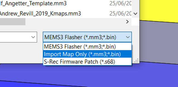
For the purposes of this example, I happen to have a tuned map for firmware version ksr3p004. It’s actually a Kmaps map that they built for the later firmware version ksr3p007, but I copied all of the later change back into an earlier Z&F Tuning ksr3p004 map (both of which I paid for, don’t ask me to distribute copies) and made some further changes of my own. So let’s load that in as one of the maps. Click Open, and change the file type to Import Map Only (*.mm3;*.bin). This will allow you to select any file containing a map and load the map only into the current project, rather than as a new project:
A dialog box like the one below will be displayed, now showing details of the two different maps:

Once you have finished editing the maps, you need to write the project back to the ECU to effect the changes made.
Because the alternate map is stored in the spare, unused space in the firmware sector of the ECU’s EEPROM memory, you MUST WRITE BACK BOTH FIRMWARE AND MAP. If you only write back the map, none of the firmware patches or the alternate map will get written back and the ECU will still just have the one main map and no switching functionality. You won’t do any harm, you just won’t get the new functionality. This is also true if you subsequently edit the alternate map. If you don’t write the firmware back, it won’t write the alternate map. Think of the alternate map as being part of the firmware.
If you’re not sure about how to do this, refer to MEMSMapper.htm.
Other Firmware
Options
You can of course use any firmware version compatible with your ECU hardware, you don’t need to stick with the firmware currently on the ECU. As you will end up with two maps and one firmware, it’s important that the two maps are for the same firmware version (the tool won’t let you write to the ECU unless the firmware version and both maps match). If you are just planning to edit the existing map, you can just work with whatever firmware version you have. If you already have a tuned map file for a particular firmware version then you can use that firmware version instead, but then both maps must be for that firmware version. Firmwares were generally built for one part number, but I’ve found that (certainly as far as features that we actually use on our Caterhams are concerned) there’s actually a wide spread of compatibility between firmware versions and part numbers.
· All petrol manual non-VVC ECUs seem to be happy running firmwares and maps for any other petrol manual non-VVC ECU.
· All VVC ECUs seem to be happy running firmwares and maps for any other VVC ECU,
· VVC ECUs even seem happy running non-VVC firmwares and maps, they just revert to acting as non-VVC ECUs.
· Auto gearbox ECUs have an extra CANbus controller chip and need appropriate firmware to control it, although with some limited testing I’ve found that these are also generally happy to run manual gearbox firmwares and maps in which case they just revert to acting as manual ECUs.
For the specific case of Caterhams, it seems that in most cases any VVC ECU (NNN100822, NNN000100, NNN000160) will do for a VVC and any MG Rover petrol manual non-VVC ECU will do for a non-VVC (e.g. NNN000060, NNN100742, NNN100743, NNN100752, NNN100783 … I’m not 100% sure about the Land Rover ECU NNN100710 but it’s probably OK too). This means that you have a lot of flexibility in cloning maps and firmwares between ECUs. It also means that a cheap Rover 25 ECU off eBay for £15 is absolutely fine to replace an expensive and hard to find Caterham Supersport ECU, you just need to flash it with the Supersport firmware and map.
If anyone needs copies stock MG Rover or Caterham firmwares or maps, give me a shout, I have a library of most of them now.
Adaptations
One thing that concerned me when I was developing this was how the ECU would handle adaptations. If the two maps specify wildly different fuelling for example, the ECU will learn to trim the fuel from the lambda sensor based on one of the maps as you drive. These trim corrections required will be different for the two maps. If the ECU learns adaptations based on one map, it will then apply the wrong corrections for the other map. In reality, from experiments on my own car, it doesn’t seem to be much of a problem. The ECU re-adapts quite quickly after switching maps. If you’ve started from one base map and made small changes as required, the two maps will probably still be quite similar and the effect will be small anyway. If you’ve started with wildly different base maps (as I did in my example above) you might want to think about the following:
· The ECU normally initialises certain variables in memory with set values when it boots up. Some of these values are taken from the active map. When you switch maps, it doesn’t reboot so it doesn’t re-run the initialisation. This can leave some values initially incorrect, but these all seem to be just starting points are and very quickly adapted and corrected by the ECU.
· The ECU will initially apply the idle adaptations learned from one map to the other on switching. If the idle air control valve settings are very different between the two maps, idle control may be compromised for a short time. You can find the idle speed wanders a little bit high or low until the ECU re-adapts. It seems to have largely corrected itself after just three or four seconds of idling, or three or four of blips of the throttle. It might be sensible to use identical or similar idle air control valve settings on the two maps, in which case this probably won’t be noticeable. You can copy idle control valve settings from one map and paste into the other in MEMS Mapper.
· The ECU will initially apply the fuelling adaptations learned from one map to the other on switching. It is probably best to make sure that there are not large differences in the fuelling between the two maps, particularly in the areas where it is set to run closed-loop. This will avoid the ECU having to re-adapt the fuel trims significantly on a map switch. Again, you can copy and paste the fuelling settings in MEMS Mapper. If you want a road map with optimal fuelling and a track map to run richer at higher RPMs and MAPs to protect the engine under harsh track conditions, the differences will mostly be well away from the areas where it is learning from the lambda sensor and should not cause an issue.
· The above comments are based on testing on my own car. Your mileage may vary!
Hardware Requirements
If you are using a physical switch, all that is required is a simple ON/OFF switch between either ECU Pin 21, Pin 47 or ECU Pin 63 and earth.
· Switch OFF, ECU pin DISCONNECTED, ECU runs main map.
· Switch ON, ECU pin GROUNDED, ECU runs alternate map.
If you are switching maps using the throttle, you don’t need to add anything at all.
Inputs
I’ve provided four options in MEMS Mapper, you can choose to use Pin 21, Pin 47 or Pin 63 for a physical switch input, or you can switch maps using the throttle:
·
Pin 21
– This is the engine bay temperature sensor input. This should work on all cars
except MG TFs. It doesn’t work on MG
TFs (which already make use of Pin 21). It is possible (although unlikely) that
some non-MG TF ECUs may omit components relating to the engine bay temperature
sensor, in which case this input may not work and you should try another input.
·
Pin 47
– This is the air conditioning evaporator temperature sensor input. This should
work on all cars without air
conditioning. It doesn’t work on air conditioned cars (which already make use
of Pin 47). It is possible (although unlikely) that some non-air conditioning ECUs
may omit components relating to air conditioning, in which case this input may
not work and you should try another input.
· Pin 63 – This is the automatic gearbox Park/Neutral switch input. This uses the simplest mechanism internally. It’s probably therefore the most robust option, if the ECU has the electronics. It seems to work fine on most non-VVC manual gearbox ECUs. It doesn’t work on later VVC 160 ECUs NNN000160 (which don’t have all of the electronics required) or on automatics (which already make use of Pin 63). Personally I’d be tempted to try this option first if your car isn’t one of the above. If the car switches permanently into the alternate map, then try the Pin 21 or Pin 47 option instead.
In any case, the interface is the same. An additional Micro Timer II terminal needs to be fitted to the corresponding pin position in the ECU connector wired to a switch to ground. The diagram below shows the three input pins viewed from the wiring side of the ECU connectors:
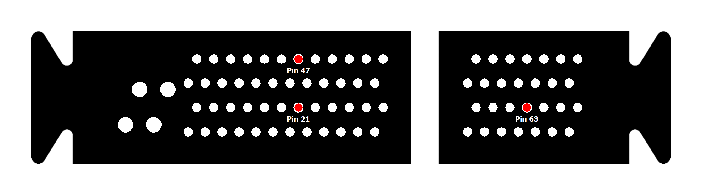
· Throttle – This is the simplest method, but is less flexible. If you place your foot on the throttle as you turn the ignition on (not as you start the engine), the ECU with run the alternate map. If you turn the ignition on without placing your foot on the throttle, the ECU will run the main map. To switch maps you will need to turn the ignition off for 15 seconds (if you hear the fuel pump prime again when you turn it back on, you know the firmware has restarted and recorded which map was selected on the throttle). Using this method you cannot switch maps while the engine is running.
Input Pin Details
I initially developed this code to work with ECU Pin 63. This is the input for the Park/Neutral switch on an automatic. This did have the disadvantage that it meant that the map switching would not work on an automatic ECU where this pin was already in use, however it had the advantage that the input was purpose-designed for a switch, had internal pullup resistor and noise filtering (I could see the response at the microcontroller pin using an oscilloscope), and was just connected almost straight to a simple port pin on the microcontroller that I could read easily in code. I tested it all on a range of test mule ECUs and it worked a treat. Then I installed on my own VVC 160 and it just would not work at all.
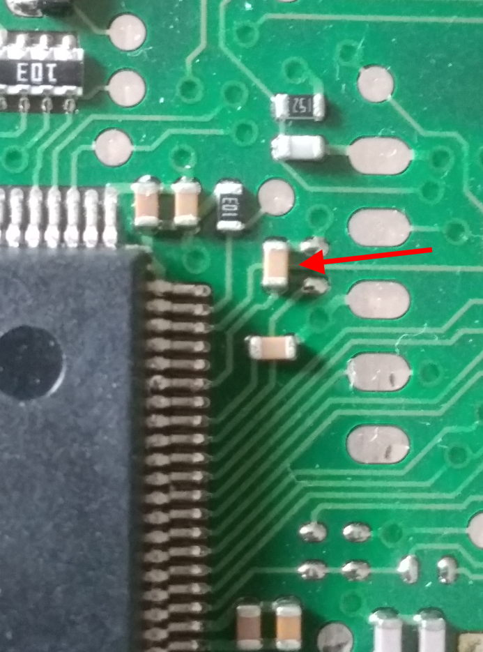
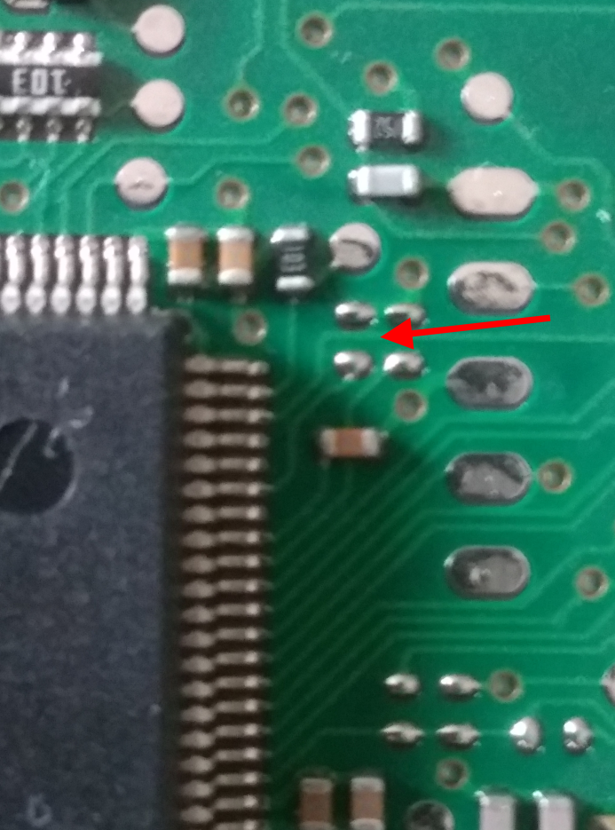
A bit of peering inside some ECUs revealed that on the later VVC 160 ECUs, they had deleted the (admittedly redundant) components for the automatic gearbox input. In the pictures below you can see an earlier non-VVC ECU on the left and a later VVC ECU on the right. You can clearly see a missing component, and the PCB trace from the bottom of that leads directly to the sixth microcontroller pin down on the right, which is Pin 75, PORTE:4 which is what I was using as my switch input. So my initial solution would not work on VVC 160s and quite probably not on some other later ECUs too.
So I set about looking for other possible inputs and it all got really difficult. Every ECU pin designated as an input was either critical to normal running, or connected into some peripheral electronics that prevented me from reading it directly (and probably also meant that switching it to ground would have side-effects as there was no way to “disconnect” it in software).
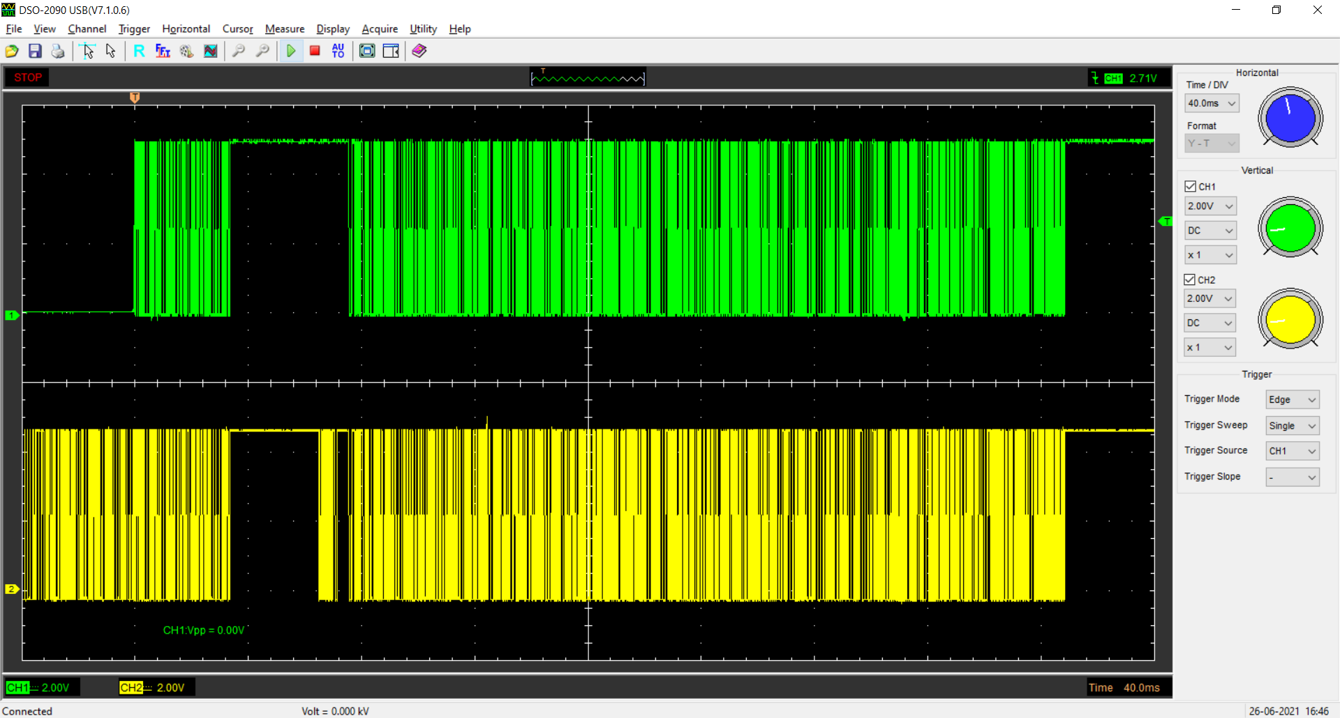
I even tried the idea of connecting a switch across the OBDII K-Line to ground. This line normally idles in the high voltage stage, it is switched to ground in short pulses to communicate, but I thought if I could detect it being pulled to a steady low voltage level by a switch I could use that as my input. Unfortunately the K Line is connected to the microcontroller’s RXD pin and internally this pin is ONLY connected to the input to the serial shifter and cannot be read as conventional input pin. Given that OBDII uses a single line for transmit and receive, I even tried reconfiguring the TXD output as an input when it wasn’t being used to allow me to read the state of the line, but it didn’t work.
In the oscilloscope trace below, the green line is the transmit data on the TXD pin and the yellow line is the receive data on the RXD pin. You can see that the RXD pin sees everything sent on the TXD pin, but there is received data on the RXD pin which is not seen by the TXD pin.
I even had the idea if enabling idle-line detection interrupts, thinking that if I kept clearing the idle line flag, I would get a string of interrupts telling that the line was idle if it was left to float high. If I wasn’t getting any valid data and I wasn’t getting any idle notifications either over a period of time, I could assume that the line was pulled low by a switch. I managed to patch all of that in and hide it from the existing OBDII routines so that they still worked normally, but unfortunately even after clearing the idle flag after an idle line interrupt, I didn’t get another. So I had no way to detect the end of the idle period.
I had the idea of maybe using unused temperature sensor inputs as they would work on everything that didn’t use that particular sensor input. So everything other than an MGTF (in the case of the engine bay temperature sensor on Pin 21) or everything except air conditioned vehicles (in the case of the air conditioning evaporator temperature sensor on Pin 47), at least covering off some more of the target cars, so I installed my table lookup debugging patch which I wrote up here: MEMS3DebugCodeInjection.htm and set it to watch Table 5 and Table 7, which I had identified previously as the air conditioning evaporator temperature sensor calibration table and the engine bay temperature sensor calibration table. The ECU was indeed actively scanning these tables as it was running, and when I shorted the inputs to ground it switched from looking up the value 1023 (corresponding to 5V) to the value 0 (corresponding to 0V).
So Pin 21 and Pin 47 were available as some sort of input, and testing showed that they seemed to respond in the same way across all the ECU hardware and firmware I had. They were actually analogue input channels with a pullup resistors that would respond to a variable resistance to ground (a temperature sensor), but then a switch to ground is just a variable resistance with only two possible values, close to zero or infinite, so a switch to ground from this pin just read as values of 1023 (5V, switch open) or 0 (0V, switch closed).
I wanted to be careful to make sure that anything I did with these unused pins would not affect engine management and running, so I trawled trough the assembly language code looking where they were processed. It turns out that the microcontroller has a queued analogue to digital converter module (QADC) and this acts almost as a small processor in its own right, in that you can give it a queue of conversion tasks to work through and it produces the results in a file of registers mapped into address space. The code looped over this register file, pulling the numbered results as defined by a list of scalars in the map and passing them through the relevant calibration tables (or in some cases simple calculation algorithms) to convert the raw numbers (voltages) into meaningful numbers (temperatures, pressures etc.). This routine wrote both the raw and converted values to arrays in RAM.
As I knew that all engines run fine with this input disconnected, when the QADC returns a result of 1023, I inserted a small patch into the start of the subroutine that loops over the QADC results. In this patch I quietly read out the results at the offsets corresponding to the input for Table 5 / Pin 47 ($0D) and Table 7 / Pin 21 ($07), stored them in variables of my own, and then wrote values of 1023 back into the results table, before calling back to the original code. This meant that I could work out from my own variables whether a switch on the corresponding terminals was open or closed (I simply regard everything as 512 or more to be “open”, 511 or less to be “closed”) but the ECU ALWAYS saw the inputs as being disconnected, as by the time it got to the ECU’s own code to process the input I’d overwritten the real value with the dummy 1023. So everything was pretty much guaranteed to continue to run as though the pin was not being used.
Tables with small indices, and the code which processes them, tends to be absolutely core to the MEMS3 family and is highly conserved across all MEMS3 firmwares with very little change indeed. In fact I’ve been doing some work with someone else who is doing a similar job on the earlier MEMS 2J (EU2 VVC ECU) and we are finding that the majority of the code is line for line identical between that and MEMS3.
The code inside MEMS Mapper does all of the analysis required to find the points in the firmware that need to be patched and to insert the patches as required; none of this logic is required to execute on the ECU as this is just patched permanently with the results of the analysis of the mapper application. As an example, here’s the start of the routine that loops over the QADC results table. It starts by clearing a lot of bits which mark particular results as being valid; each of these bits get set again is it processes the latest inputs. In every version of the MEMS3 firmware there are several of the BCLR instructions right at the start, so I’ve searched for occurrences of at least three consecutive BCLRs as shown in red below, followed within a certain range of offsets (to allow for possible small changes in the code) by the specific instructions in the second red block. These quite specifically load a value from of an array in the map scalar data indexed by register d5 into register d4, load the address of the QADC results file into register a2 and load the address of an array in RAM to receive the results into register a1. This uniquely finds the correct subroutine in all petrol firmware versions, but the TD5 diesel code differs and this does not find it.
ROM:001105B6
bclr #5,(Variable $8FA).w
ROM:001105BC
bclr #5,(Variable $8E7).w
ROM:001105C2
bclr #3,(Variable $8F3).w
ROM:001105C8
bclr #5,(Variable $8F9).w
ROM:001105CE
bclr #1,(Variable $8EA).w
ROM:001105D4
bclr #7,(Variable $8ED).w
ROM:001105DA
clr.w d7
ROM:001105DC
move.w (Scalar $13C734),d6
ROM:001105E0
cmpi.w #0,d6
ROM:001105E4
ble.s locret_110622
ROM:001105E6
ROM:001105E6 loc_1105E6:
ROM:001105E6
cmp.w d7,d6
ROM:001105E8
ble.s locret_110622
ROM:001105EA
move.w d7,d5
ROM:001105EC
addq.w #1,d5
ROM:001105EE
move.w (Scalar Array $13C734,d5.w*2),d4
ROM:001105F4
lea (Variable QADC Register RJURR Table).w,a2
ROM:001105F8
lea
(Variable $E9E).w,a1
ROM:001105FC
move.w (a2,d4.w*2),d2
ROM:00110600
move.w (a2,d4.w*2),(a1,d4.w*2)
I then overwrite the first BCLR instruction (which takes 6 bytes) with a subroutine call to my own routine (a JSR also takes 6 bytes), which does this:
_patch_qadc:
OPT NOWAR * Execute
instruction replaced by patch.
bclr.b
#5,($8FA).w * Firmware
ksr3p007 only!
OPT WAR
move.w (QADC_RJURR_PIN47),(_qadc_result_pin47) * Copy QADC
result for Pin 47 to variable.
move.w
#$03FF,(QADC_RJURR_PIN47) * Substitute
default QADC result for Pin 47.
rts
This starts by executing the instruction that was overwritten, then copies out the QADC result, replaces it with hexadecimal $3FF (1023) and returns to the firmware code to continue none the wiser.
The option to switch maps using Pin 21 works identically to the Pin 47 method, however this time the QADC result for the engine bay temperature Sensor is checked.
The option to switch maps using the throttle works in a very similar way to Pin 47, however this time the QADC result for the TPS is checked and recorded only on the first pass after the ignition is switched on. From then on, it uses the recorded value to determine which map to use on each pass of the loop. The only way to switch maps is to turn the ignition off for long enough to allow the firmware to shut down and reload.
How The Map is
Actually Switched
The ECU code is written as a short initialisation section, followed by a loop which just executes round and round indefinitely. Each of these blocks calls many subroutines which do the work of the ECU, updating calculations and setting parameters for the hardware components. The ECU loads the address of the map, by default $13C00 into register a5 from a RAM variable at the start of each pass through this loop. All references to scalars and tables in the map are then coded as references to offsets from the address pointed to by a5. This RAM variable is set to $13C00 by the initialisation code and usually just remains set, however there are some complex OBDII-based routines which can set this variable to point to another location, effectively switching to another map. The actual switch happens when register a5 is loaded at the start of the loop and all map references are then relative to the new map location.
The code which sets up the RAM variable is complex and opaque but what is clear is that it sometimes sets it $1400 and sometimes to $140000. The ECUs RAM addresses go from $0000 to $13FF so $1400 is the start of non-existent memory just beyond the end of the actual physical RAM. The ECUs EEPROM addresses go from $110000 to $13FFFF so $140000 is once again the start of non-existent memory just beyond the end of the actual physical EEPROM.
All of this points to the fact that the firmware was written to run both on the production ECU and on some sort of development system, which presumably had additional memory installed at these addresses. The fact that one of the options points the map at what was presumably RAM suggests that the development system supported live mapping, with some way to copy the map changes from RAM to EEPROM when done. In fact my friend who is working on MEMS 2J has found all of this code and has succeeded in soldering some additional RAM onto a MEMS 2J ECU bus connector and getting it all working!
In my code, I’ve inserted a patch in a similar way to the one done for the code which gets the QADC results above.
This is how the main execution loop of the firmware typically starts:
ROM:001156B0 loc_1156B0:
ROM:001156B0 movea.l
#$400,sp
ROM:001156B6 move.w sp,(Variable $53E).w
ROM:001156BA movea.l
#word_13C000,a5
; point register a5 to start of map
ROM:001156C0 move.l a5,(Variable Map
Base Address).w
ROM:001156C4 bsr.w Copy Point
Subroutine sub_1158BE
ROM:001156C8 bsr.l Subroutine
sub_116056
ROM:001156CE clr.w (Variable $4CC).w
ROM:001156D2 bsr.l Subroutine
sub_119524
ROM:001156D8 bsr.l Point Subroutine
sub_110D06
ROM:001156DE bsr.l Copy Point
Subroutine nullsub_52
ROM:001156E4 bsr.l Copy Point
Subroutine sub_115E1E
ROM:001156EA bsr.l Point Subroutine
sub_11086A
ROM:001156F0 bsr.l Point Subroutine
sub_11143E
ROM:001156F6 bsr.l Point Subroutine
sub_111422
ROM:001156FC bsr.l Point Subroutine
sub_135582
ROM:00115702 move.b #0,(Variable SIM
Register PFPAR).w
ROM:00115708 move #$2000,sr
ROM:0011570C
ROM:0011570C ; This is the start of the main program loop.
ROM:0011570C
ROM:0011570C main_program_loop:
ROM:0011570C move.b #$55,(Variable
Software Watchdog Service Register).w ; reset
watchdog service step 1 of 2
ROM:00115712 move.b #$AA,(Variable
Software Watchdog Service Register).w ; reset
watchdog service step 2 of 2
ROM:00115718 movea.l (Variable Map Base Address).w,a5 ; point register a5 to start of map
ROM:0011571C addq.w #1,(Local
Variable $C1A).w
ROM:00115720 bvc.s loc_115728
ROM:00115722 move.w #$8000,(Local
Variable $C1A).w
You can see that register a5 is loaded from the variable I’ve named Map Base Address in the initialisation section before the loop at ROM:001156C0 and then again at the start of each pass of the loop at ROM:00115718.
The actual main firmware routine is very easy to locate in any firmware as it’s the Reset Exception handler (it gets called whenever the ECU resets) and so its address is specified in the Vector Table right at the start of memory. Within this routine, the start of the loop is also very easy to spot, as the first thing it does is to reset the watchdog timer:
ROM:0011570C move.b #$55,(Variable
Software Watchdog Service Register).w ; reset
watchdog service step 1 of 2
ROM:00115712 move.b #$AA,(Variable
Software Watchdog Service Register).w ; reset
watchdog service step 2 of 2
This is basically a hardware feature whose job it is to reboot the ECU quickly if it ever crashes. The watchdog timer required the code to write the bytes $55 and $AA to it, in sequence, every few milliseconds to prove that it is still alive and well. If this doesn’t happen in a timely manner, the watchdog reboots the ECU to recover normal operation. The watchdog reset instructions are very distinctive and always the same, so where these are found shortly after the main routine entry point, this is the point to patch in the map switch.
I overwrite the first watchdog instruction with a jump into my patch. Unfortunately this time the instruction being replaced is only 4 bytes long and a JSR or JMP takes 6 bytes, so the second watchdog instruction is also partially overwritten. So in this case we can’t just call the patch as a subroutine and let it return to where it left off afterwards as it would start up again half way through an instruction. Instead I hardcoded the patch to execute BOTH of the watchdog instructions, then jump back to the point immediately following the second instruction:
_patch_loop:
OPT NOWAR * Execute
instructions replaced by patch.
move.b #SIM_SWSR_55,(SIM_SWSR).w
move.b #SIM_SWSR_AA,(SIM_SWSR).w
OPT WAR
move.l d0,-(sp) * Save registers
(PATCH: Preserves ALL).
move.w (_qadc_result_pin47),d0 * Read QADC
result for Pin 47.
btst.l
#9,d0
beq _patch_loop_map_alternate
move.l #ADDR_BASE_MAP_MAIN,a5 * Use main map.
bra
_patch_loop_store
_patch_loop_map_alternate:
move.l #ADDR_BASE_MAP_ALTN,a5 * Use alternate map.
bra
_patch_loop_store
_patch_loop_store:
move.l (sp)+,d0 * Restore
registers.
jmp
PATCH_LOOP_RET
The patch code (in this case taken from the Pin 47 patch) loads the QADC result we copied into a RAM variable in the previous patch, checks Bit 9 (equivalent to testing whether the result value, in the range 0-1023, it greater than or equal to the half way value of 512) and then sets register a5 to point to either the main map or the alternate map.
Feedback & Help
If anyone tries this out and has any feedback, please get in touch with me at andrew.d.revill@googlemail.com.
Similarly if anyone wants me to help setting a car for dual-map switching, please do get in touch.