Importing TunerPro XDF Definitions
for Td5
Download
Link: https://andrewrevill.co.uk/Downloads/MEMSTools.zip
Importing TunerPro XDF Definitions
for Td5, e.g. from DiscoTd5.com.
Paul Jacobson at DiscoTd5.com has done a lot of brilliant work reverse engineering the Td5 ECU. For a very fair and modest donation, he provides table and scalar definitions for all of the common map and firmware combinations.
Now that I am providing pretty much full support for the Td5 ECU in MEMS Mapper, it would be good if it could be used with Paul’s definitions. As Paul’s work is chargeable and mine is distributed for free, unfortunately I can’t include his definitions in the files routinely distributed with MEMS Mapper, but I have provided an import mechanism to allow those people who use MEMS Mapper and who have purchased Paul’s definitions to use the two together.
World Views
There are few differences in “world view” between how MEMS3 Mapper and the XDF files model the ECU. The most significant of these is that there is one XDF file per FIRMWARE/MAP combination, which defines tables by their ADDRESS (as required by TunerPro), whereas MEMS Mapper has one set of definitions per FIRMWARE ONLY which defines tables by their INDEX. The same table can appear at different addresses for different maps for the same firmware, and within MEMS Mapper you can insert and delete axis values which causes the sizes of tables to change and other tables to move to different addresses. Because of this, it’s not possible to just import an XDF definition in isolation; it must be imported into a specific project. This allows MEMS Mapper to lookup the corresponding table indices for the addresses specified in the XDF file. Once an XDF file has been imported into a project, the definitions are then available for all projects for the same firmware version as usual.
Importing Definitions
To import definitions from an XDF file, you firstly need to open a project (open a file or read an ECU).
Then select Tools | Import Definitions | Import TunerPro XDF Definitions from the menu:
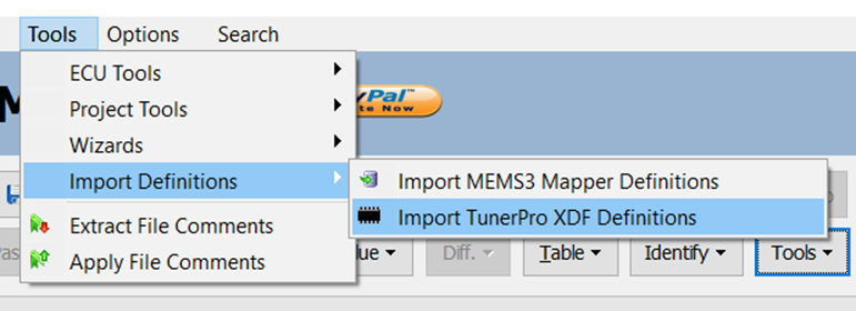
When prompted, select an XDF file which matches the firmware and map versions for the project.
Job done! The project should now show all of the tables and
scalars defined in the XDF file. Comments and identifiers previously entered
are merged into the new definitions and retained. As the definitions in MEMS3
Mapper are stored by firmware ID, these definitions will automatically be
applied to any other projects with the same firmware ID, with no need to
re-import the XDF file, even for different maps where the table addresses
differ.
XDF File Format
Requirements
As Paul’s definitions for Td5 are the only XDF files likely to be encountered, the import is rather tailored to his specific use case. The format of the file is shown below. I’ve simplified it by only including those elements which MEMS Mapper actually expects or reads. Any other elements are ignored. Elements missing will just leave properties set to default values.
<XDFFORMAT>
Once Per Table:
<XDFTABLE>
<title>Table Name</title>
<description>Table Comments</description>
<XDFAXIS id="x">
<EMBEDDEDDATA mmedaddress="Hex. X Axis Address Offset from 0x13C000"
/>
<units>X Axis Name</units>
<decimalpl>X Axis Decimals</decimalpl>
<MATH equation="X Axis Scale &
Offset Expression">
</MATH>
</XDFAXIS>
<XDFAXIS id="y">
<EMBEDDEDDATA mmedaddress="Hex. Y Axis Address Offset from 0x13C000"
/>
<units>Y Axis Name</units>
<decimalpl>Y Axis Decimals</decimalpl>
<MATH equation="Y Axis Scale &
Offset Expression">
</MATH>
</XDFAXIS>
<XDFAXIS id="z">
<EMBEDDEDDATA mmedaddress="Hex. Z Axis Address Offset from 0x13C000"
/>
<units>Z Axis Name</units>
<decimalpl>Z Axis Decimals</decimalpl>
<MATH equation="Z Axis Scale &
Offset Expression">
</MATH>
</XDFAXIS>
</XDFTABLE>
Once Per Scalar:
<XDFCONSTANT>
<title>Scalar Name</title>
<description>Axis Name</description>
<EMBEDDEDDATA mmedaddress="Hex. Scalar Address Offset from 0x13C000"
/>
<decimalpl>Axis Decimals</decimalpl>
<MATH
equation="Axis Scale & Offset Expression">
</MATH>
</XDFCONSTANT>
</XDFFORMAT>
· Addresses for axes and scalars are specified in the form “0x123”, which is interpreted as a hexadecimal offset from the start of the map at 0x13C000, so in this case the address would be 0x13C123.
· Addresses for tables are calculated as 4 bytes before the address of the X axis data.
· Axis scale and offset expressions in the following forms are recognised and decoded. All other expressions are not decoded will return a Scale of 1 and an Offset off 0. N1 and N2 represent any positive decimal number:
o (X+N1)/N2 Scale = 1/N2, Offset = N1/N2.
o (X-N1)/N2 Scale = 1/N2, Offset = -N1/N2.
o X+N1 Scale = 1, Offset = N1.
o X-N1 Scale = 1, Offset = -N1.
o X/N1 Scale = 1/N1, Offset = 0.
o X Scale = 1, Offset = 0.
These requirements seem to give sensible results with all of Paul’s XDF files.