Recreating the Caterham SuperSport
EU2 ECU
Recreated / Remanufactured Caterham
SuperSport EU2 MEMS 1.9 ECUs are now Available for Sale – Email
Me
I’ve been
wondering for some time whether it was possible to recreate the Caterham
SuperSport EU2 MEMS 1.9 ECU. It bothered me that if these ECUs failed,
replacements were just impossible to find now. The engine breathing with the
SuperSport cams is sufficiently different to mean that an ECU mapped with a
standard Rover calibration delivered fuelling that was hopelessly incorrect.
These ECUs are not reprogrammable; the microcontroller chip used can only ever
be programmed once. In the case of the MEMS 1.9 ECU, they were programmed at
manufacture and can never be erased to allow reprogramming. So, it is not even
possible to reprogram a Caterham RoadSport or Rover ECU with the SuperSport
files.
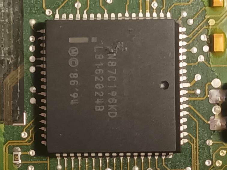
The microcontroller used is a very
specific automotive version, the Intel AN87C196KD and long obsolete (about a
40-year-old design). Even finding programming equipment that can handle this
chip is difficult these days. I got as far as locating some blank, unprogrammed
microcontrollers of the correct type but then other priorities took over and
they sat on the shelf. Until recently …
I was approached by someone with a weird
electrical fault. The ECU had been intermittently shutting down, and the engine
was now in a state where it would not run at all. After some diagnostics using
MEMS3 Mapper it was clear that the ECU had developed an internal fault, would
not run the injectors, and was reading the analog inputs incorrectly. This gave
me the incentive needed to resurrect the project. Since then, I’ve seen another
two failed SuperSport ECUs which convinced me that there was indeed a need to
be able to replace them.
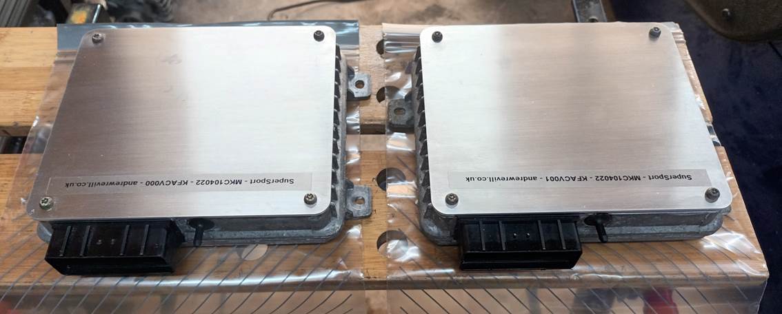
I looked at the hardware inside a few
different part numbers of MEMS 1.9 ECU and managed to convince myself that the
common Rover 200 ECU MKC104022 looked to be pretty much identical to the
Caterham SuperSport ECU in all important respects and that it was worth trying
to resurrect the SuperSport ECU by transplanting the microcontroller chip from
the failed SuperSport ECU into an MKC104022. From my experience of MEMS3 I
expected the code to be written in such a way that any additional modules
present not expected by the firmware would just be ignored, and any modules
missing would at worst fail and log a fault leaving the rest of the ECU running
correctly. As far as I could see the only differences between the two boards
were some 0 Ohm resistors used as option selector jumpers were not present in
the MKC104022, but in every case it appeared that the board was modified to
“hard code” these same options and the 0 Ohm resistors were simply replaced by
copper tracks between the pads. In the end, the hybrid ECU I produced worked
fine and was kindly tested for me by another member who allowed me to plug it
into his car and test drive it. It reported the SuperSport calibration and was
in all practical respects identical to a regular SuperSport ECU. It has since
been reinstalled into the car and is running correctly. It idles and drives
correctly and no fault codes are logged.
That ECU was enough to prove that the
idea was viable, so I set about doing it properly, using the above ECU as the
prototype.
I used the new MEMS 1.9 support in MEMS3
Mapper to read the ROM contents of several SuperSport ECUs and compared the
results. There were only two calibration files found, namely KFACV000 and
KFACV001. There is very little difference between these and KFACV001 appears to
be just a minor evolutionary revision of KFACV000. There’s not much to choose
between them in terms of car performance.
I then managed to locate a company that
was able to program the microcontrollers I had purchased. They had a minimum
order value of £50 but for that they were happy to program 5 of each file. We
encountered a couple of teething problems with the first two programmed. In a
nutshell there are a couple of security bits in the files, when these are
written with 0 the ECU is secured and cannot be read, and they were 0 in the
files read from the SuperSport ECUs, so once the chips were programmed, they
could no longer be read, but the programming equipment did not understand this,
tried to read and verify the chips and marked them as verification failures.
For later chips I changed those bits to 1 to avoid the issue but it turned out
the first 2 had still programmed correctly and were still usable (once
installed in an ECU I was able to read them through the firmware using MEMS3
Mapper and verify them via that route).
I then bought some MKC104022 ECUs on eBay
and set about perfecting the process of converting them. I’ve bought enough
parts to make 10 new ECUs, at the time of writing I have completed 8, and 3 of
them were sold before I had even finished them. I’m happy to make more at some
point in the future if required, but I’ve also written up the process in detail
below in case anyone else wants to have a go. I’ve included copies of the final
versions of the KFACV000 and KFACV001 files for download. It took a few attempts
to get this process sorted and a few ECUs were lost along the way. I’ve
described the various pitfalls and problems I encountered in the detailed
notes. But the process below is now reliable and I’ve managed to complete the
batch of reproduction Caterham SuperSport ECUs satisfactorily using this
process.
The new ECUs are finished with smart new
laser-cut lids as the process of opening the ECU casing was rather destructive.
The Conversion Process
The starting point is a Rover MKC104022
ECU. There were used on Rover 200 and 400 cars and are readily available from
salvage through eBay etc. Any ECU with this part number should be
hardware-identical and equally suitable, whatever the source vehicle. To be
honest, because the Caterham installation only uses the basic core features of
a Rover installation, I suspect that many other MEMS 1.9 part numbers would
work just as well, but MKC104022 has been tried and tested so is a safe option
and that’s what I’ve stuck with.
The first thing I do is to give the ECU a
good wash with engine degreaser. Some used ECUs can be pretty grotty and a bit
corroded on the outside. This also gives a good opportunity to look for any
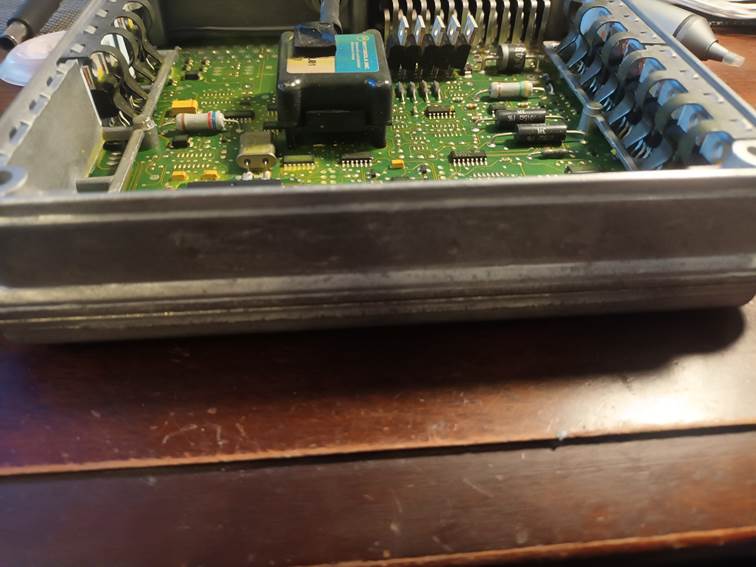
obvious mechanical damage. The external pipe nipples for the internal MAP
sensors are particularly vulnerable to damage and can fracture in use. The top
covers on these ECUs are neatly always quite badly dented and damaged. These
are replaced as a matter of routine as part of the conversion so this doesn’t
matter.
On the outside of the ECU case is a label which contains various build codes in addition to the part number MKC104022.
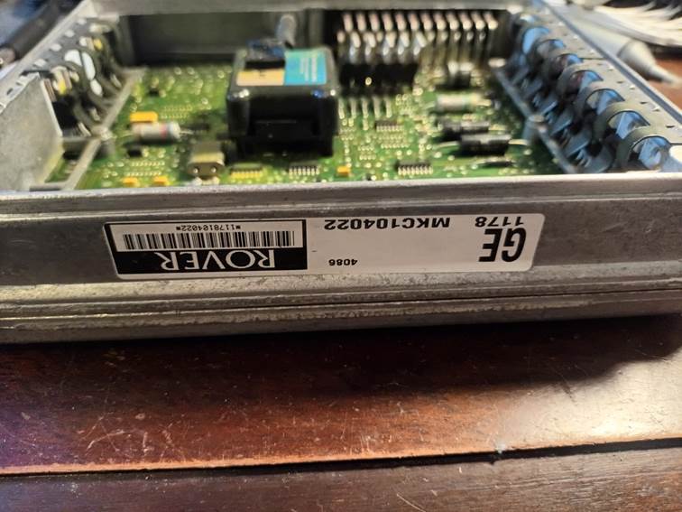
I remove this just to make sure that the ECU never gets mistaken for a stock Rover ECU. With care it can be peeled back without leaving any glue residue.
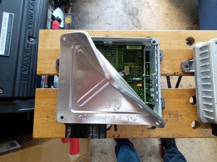
The ECU lid can then be removed by
removing the four screws and prising the edges up with a flat bladed
screwdriver. The four screws are an odd thread, something imperial and similar
to #6-32 but with about 27 threads per inch instead of 32. I took them to a
local fastener specialist and he was unable to identify it supply replacements,
but he was able to say that they looked like some sort of self-tapping thread
which fitted with the fact that they were always stiff to unscrew. They’re
sometimes a bit corroded and not so pretty but as I’ve been unable to source
any alternatives, they need to be retained and reused. The lid is glues with
silicone sealant all round. I’ve tried various options including heat and
chemicals the release the silicone leaving the lids undamaged bit it never
works. So, I now routinely replace the lids with laser-cut plates and the old
lids can just be ripped off and discarded.
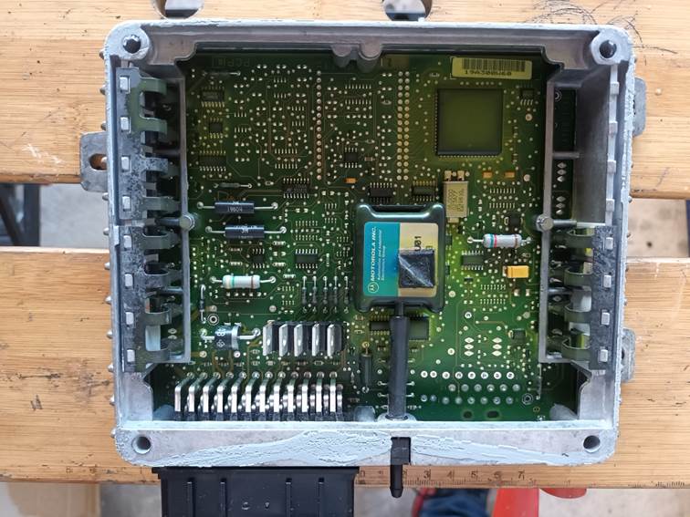
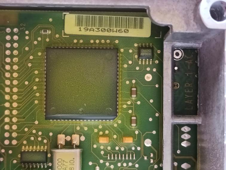
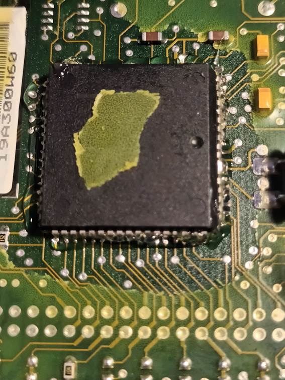
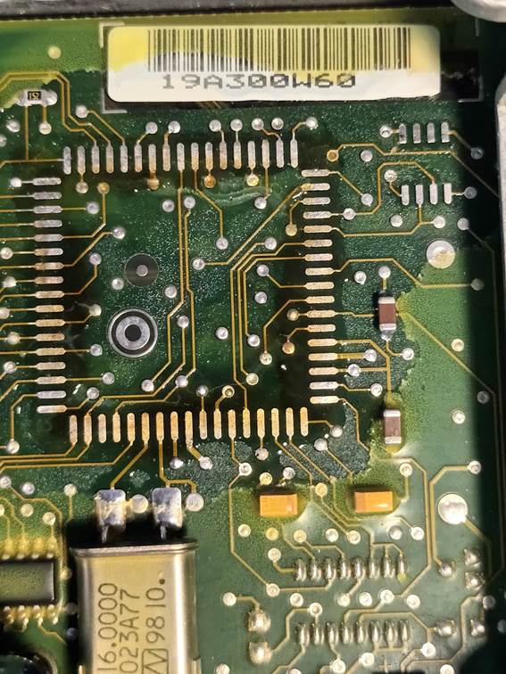
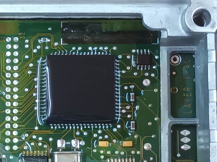
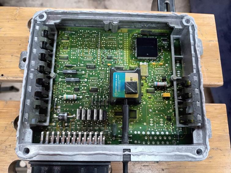
This is the view of the ECU internals once the lid has been removed. You can see that the whole circuit board is coated in a conformal silicone coating to waterproof it. This makes soldering and repairs pretty much impossible and needs to be stripped from the relevant areas of the board. There’s also a lot of residual silicone sealant around the edges which needs to be scraped away and rubbed down with Scotch Brite abrasive in order to ensure that the new lids can be sealed down properly. I clean the old sealant off at this stage as the ECU will go through various stages of cleaning as the process is followed and this ensures that any loose scraps of residual silicone are removed by the time the conversion is complete.
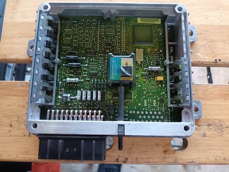
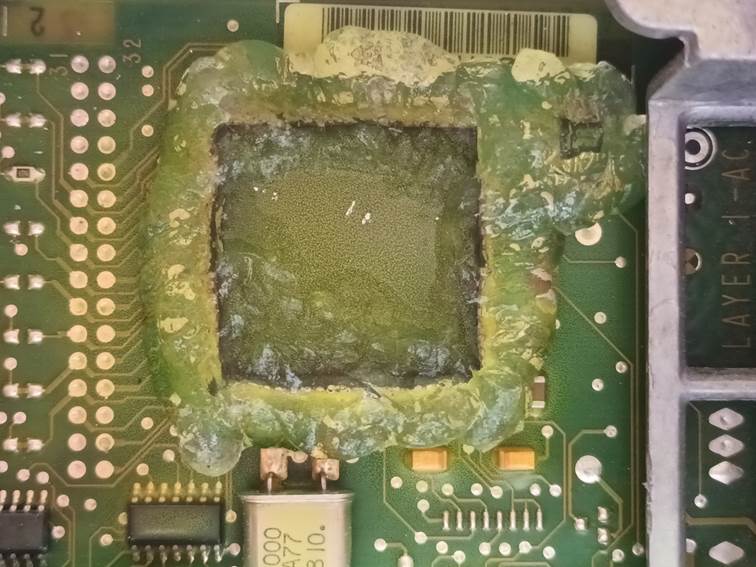
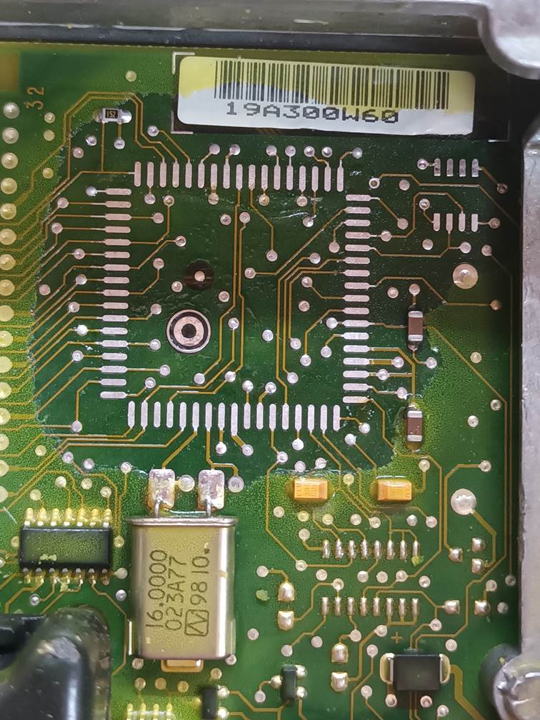
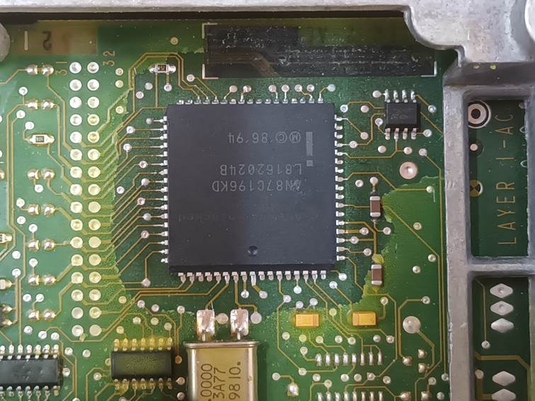
This view shows the same ECU once the silicone sealant has been scraped off and rubbed down.
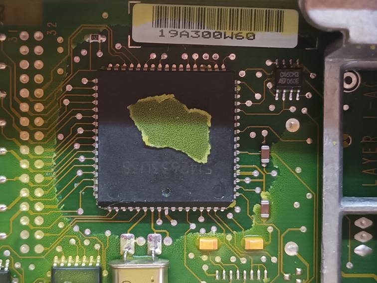
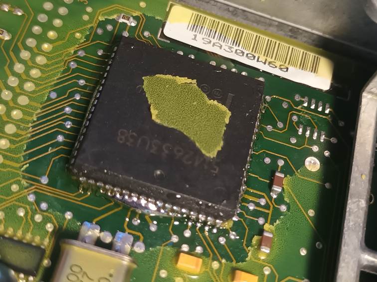
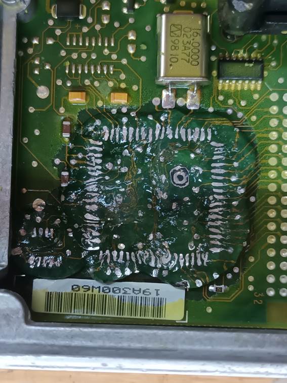
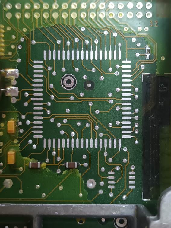
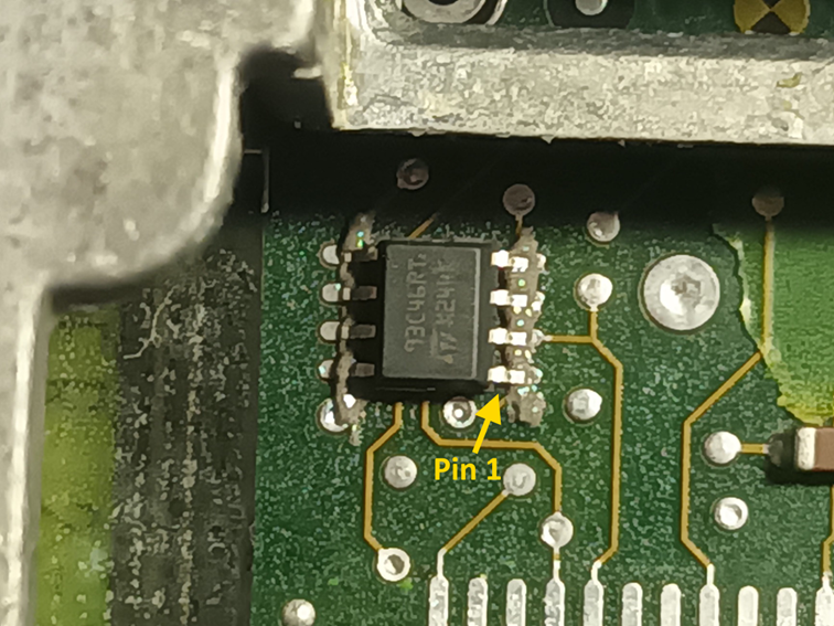
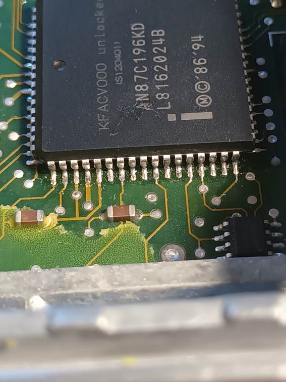
Here you can see the conformal silicone coating over the main AN87C196KD microcontroller chip and the 93C46 serial EEPROM chip. Both of these chips are to be replaced. The main microcontroller will be replaced with a freshly programmed, new chip. The serial EEPROM holds runtime settings and as the format may be different to the original firmware, it is safest to erase this chip. This “virginises” the ECU which then believes it is brand new and is ready for configuration. The ECU detects a completely erased serial EEPROM and reinitialises it with correct and appropriately formatted defaults. As these chips cost about £0.20, as I have some reason to suspect that failures of these chips are at least partly involved with some of the ECU failures I have seen and as the old chips will have been heat-stressed during removal, rather than erasing them I just replace them with brand new, blank chips. These need to be 93C46 chips with the industrial / automotive extended temperature range rating.
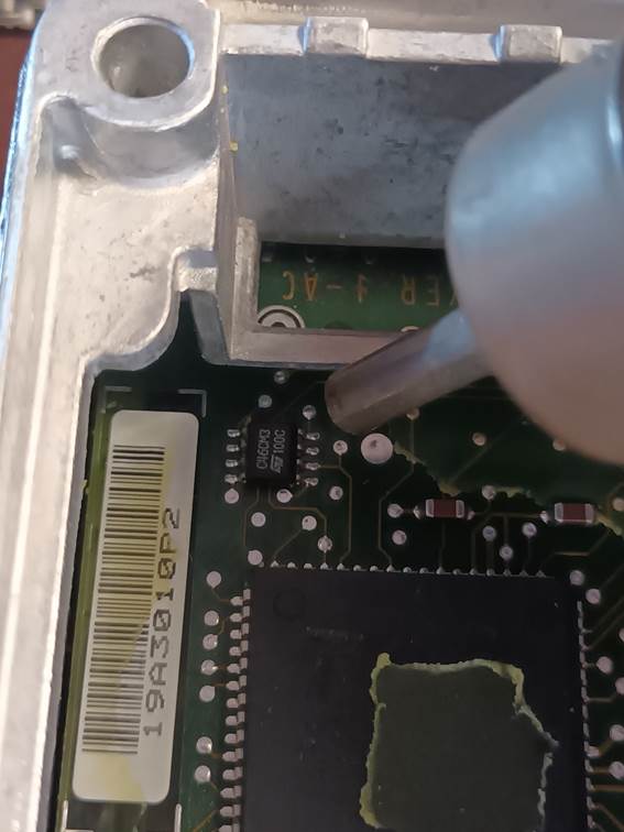
To strip the silicone conformal coating, I just use Unibond Silicone Sealant Remover in a tube from B&Q. It comes in the form of a jelly which is convenient for application to limited areas. You need to apply it to a thickness of at least 5mm over the areas to be stripped. The silicone used is particularly tough and hard to break down compared to bathroom sealants, so I have found it best to apply generously and instead of leaving on for the 3 hours recommended, leave it on for 12 hours overnight. Be careful with the silicone remover it’s quite nasty. The notes for it say that it can cause chemical burns. While that sounds dramatic, even traces of it on your skin do seem to lead to rather sore fingers afterwards and although it doesn’t smell particularly strong or unpleasant (it has a paraffin-like odour), if you work too close to it without ventilation your eyes can get really irritated by the fumes.
After a few hours, the silicone remover dries and cracks and can be removed cleanly using a vacuum cleaner nozzle.
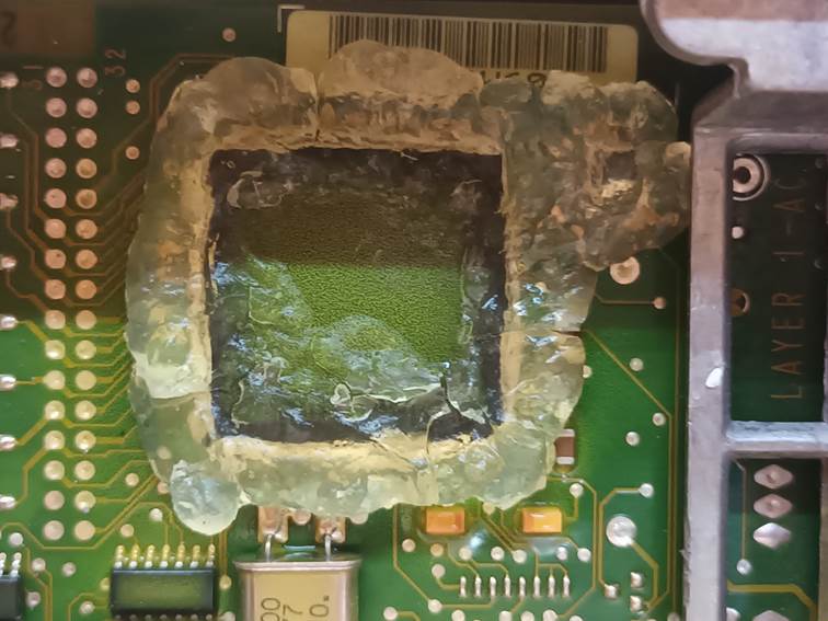
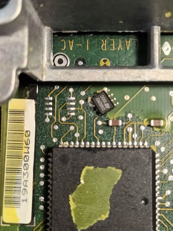
This is what is left behind after removing the silicone sealant remover. The silicone in the areas to which it was applied is reduced to a degenerate jelly-like mush that can be cleaned away using isopropyl alcohol and a small stiff paintbrush. Again, vacuum cleaner nozzle is convenient for extracting the isopropyl alcohol and silicone residue. Several stages of washing are necessary in order to remove as much of the silicone as possible.
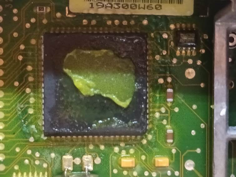
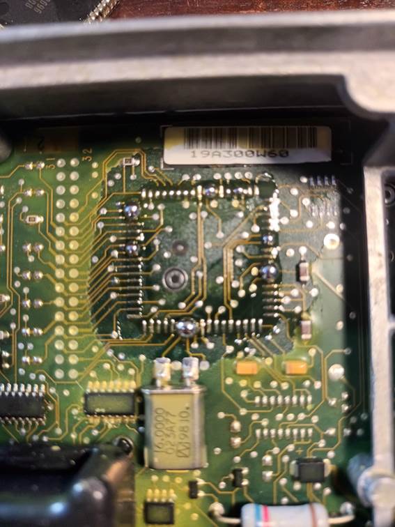
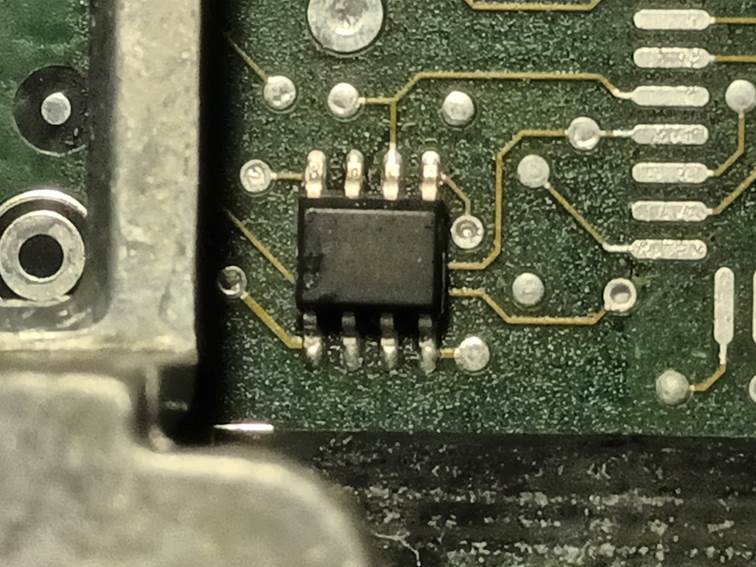
This is what the area of the circuit board looks like after cleaning away the degraded silicone with isopropyl alcohol. The pins of the two ICs are now clean and exposed ready for desoldering.
The 93C46 can then be desoldered easily using a temperature-controlled hot air rework gun set to 250°C and a small nozzle with plenty of air flow to remove the chip quickly. The chip can be lifted away gently with tweezers as the solder melts. Be sure not to apply any significant force as there is the danger of pulling a pad off the circuit board which would render it unusable. Temperatures much above 250°C can scotch the board, and make it more likely that other components may be dislodged. 250°C and a good rate of air flow seem to allow the chip to be removed quite quickly without collateral damage.
Here is the 93C46 removed.
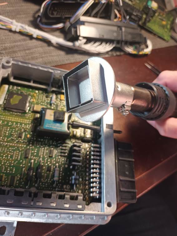
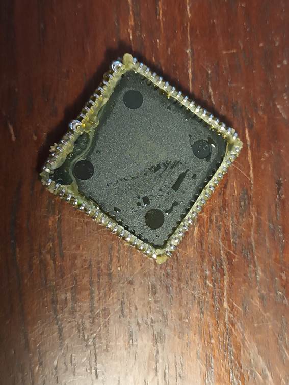
Removal of the AN87C196KD without damaging the board at all is rather more difficult. It has 68 pins in a PLCC package which is awkward because the chip terminals are folded back underneath the chip package and the soldered joints actually lie under the chip. The first stage is to apply generous quantities of ChipQuik SMD291 tack flux to all of the pins.
ChipQuik desoldering alloy is then applied. The flux and the alloy can be purchase as a kit, part number SMD1. The Indium/Bismuth alloy has an extremely low melting point of 58°C. It melts if you put it a cup of hot water. It works with the SMD291 flux to alloy with and displace the solder on the IC pins, lowering the melting point and lowering the temperature needed to remove the chip. You need to work it in well along all of the pins with a soldering iron to be sure that every pin will come free at a relatively low temperature.
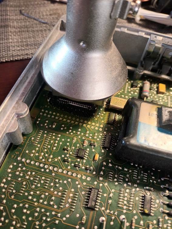
I then use a specific PLCC68 nozzle on my hot air rework gun. This allows the hot air to be directly just where it is needed around the ECU pins. I use a temperature of around 180°C. This helps to ensure that all of the pins can be kept hot and all of the joints can be melted simultaneously, but it’s just below the melting point of regular solder and so there is little risk of accidentally melting the solder on surrounding components.
I usually work around the four sides of the chip melting the alloy with a soldering iron, then apply the hot air to prevent things from cooling. I continue to work around the four sides with the soldering iron until the chip comes loose. This is where you have to be really careful. The problem is that the conformal silicone coating used leeches under the chip and glues it to the board. You have to be able to distinguish between the adhesion of the silicone and pins which are still soldered. It takes some force to tear the silicone and if you apply that sort of force with even one pin still soldered down it will just rip the pad and track off the board and render it scrap. I found the if really work around the chip with the soldering iron under the hot air until everything is really liquid, at some point gently pressing on the chip edges will cause it to rotate very slightly parallel to the board. Once it you can wiggle it a bit in rotation, and you can see that it is rotating about a centre point and all of the pins are moving, you know that it is just held down by silicone. At this point there’s nothing to do but grab it with tweezers and wrench it free, ripping the silicone and hopefully laving all pads and traces intact.
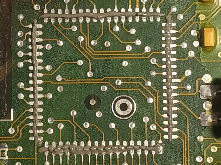
This is how the board looks immediately after lifting the chip You can see big blobs of molten alloy. There will remain liquid until quite cool, and it’s important to be careful not to splash this around the board. All of the alloy and residual solder can be removed with care with a soldering iron and desoldering braid. Again, any desoldering alloy mopped up by the braid tends to remain liquid a lot longer than expected so you need to remove carefully and allow to cool without splashing which could lead to short circuits on the board. It is also important to clean off as much of the solder and alloy from the PCB pads as possible using the desoldering braid as even relatively small amounts of residual desoldering metal will alloy into the new soldered joints and lower the melting point significantly. The left-over tack flux residue helps with solder removal.
This is the desoldered microcontroller after removal. In this case we will be replacing it and the old microcontroller can be discarded. Despite the heat used to remove it, it will still be intact and perfectly usable once cooled. They’re quite tough, it’s possible to clean up the residual silicone and solder and solder them into another board if required. If the soldering process for the new microcontroller goes wrong, for example if an unresolvable solder bridge forms under the chip, it is occasionally necessary to desolder the new microcontroller in the same way. The board can be cleaned up again as shown here and the excess solder can be removed from the microcontroller pins with a soldering iron and desoldering braid and the chip can then be soldered again.
This is how the circuit board looks once the excess solder and desoldering allow has been mopped up. The remaining tack flux can be washed off using isopropyl alcohol again, and again I find vacuum extraction works well.
This is how the circuit board looks after cleaning with alcohol. You can that there is still residual conformal silicone in areas between the pins and areas which were under the chip which will prevent the new chip from sitting perfectly flat. Because of the lack of access and because the PLCC68 package actually connects to the board under the edge of the chip, soldering the new chip in can be challenging and can lead to the formation of solder bridges between pins under the chip where they simply cannot be removed. In order to have the best chance of soldering the new chip in successfully we need to remove every last trace of silicone from the chip areas.
Another treatment with silicone remover is therefore in order.
After several hours, the second layer of silicone remover can be removed with vacuum and cleaned up using isopropyl alcohol and a stiff brush as before. This leaves the chip areas of the circuit board clean and free of silicone, solder and flux residues ready for the new chips to be soldered in.
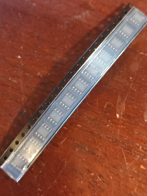
The replacement serial EEPROM chips are of type 93C46 with the industrial / automotive extended temperature range rating. I used chips manufactured by STMicroelectronics (as were the originals) with the full part number M93C46-RMN3TP/K form Mouser Electronics here: https://eu.mouser.com/ProductDetail/STMicroelectronics/M93C46-RMN3TP-K?qs=4b8myOmUP%252BvjGiy5kb6y%252BQ%3D%3D&countryCode=GB¤cyCode=GBP. These are supplied in an antistatic cut tape as show below.
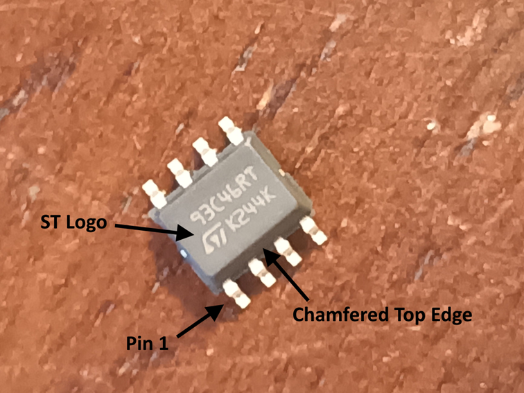
Identification of Pin 1 of these chips is a bit tricky. You need good eyesight or a jeweller’s loupe. They have one (slightly) chamfered top edge. For STMicroelectronics chips, the ST logo is also closest to Pin 1.
To solder these chips to the board, I use low melting point (Tin 42%, Bismuth 58%, 138°C) solder paste. A thin sausage of tis is laid out across the rows of pads on the board as shown.
The chip is then placed onto the pads with Pin 1 closest to the main microcontroller as shown. Care must be taken the place the chip accurately with the pins aligned to the pads on the board and with the minimum of sliding around, which can lead to uneven distribution of the solder paste.
And then a temperature controlled hot air rework gun at 220° with a suitably small nozzle is applied to melt the solder and fix the chip in place. The solder paste contains flux which ensures that the solder withdrawn back into the joints under surface tension and wets all of the chip leads and board pads.
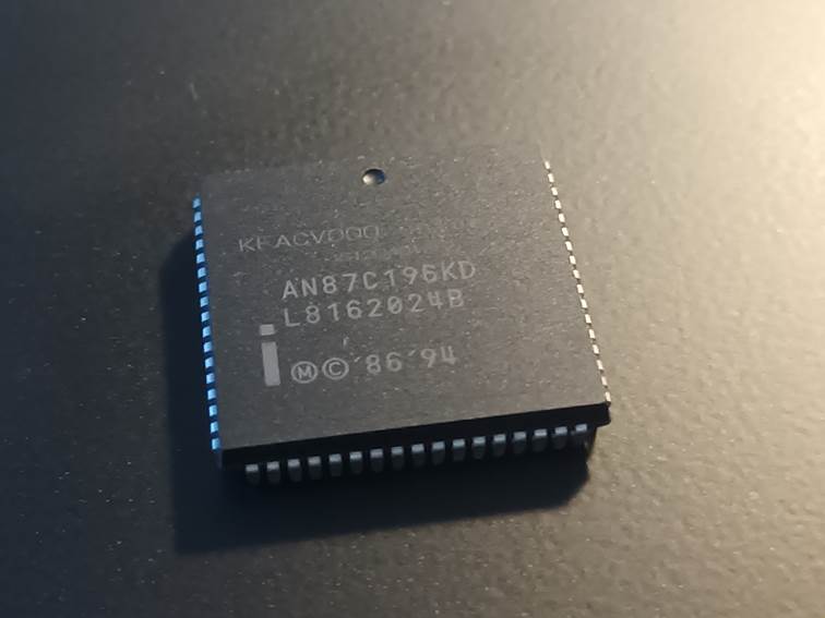
The new microcontroller chips are of type
AN87C196KD. They are log obsolete from Intel but can still be obtained from
obsolete silicone stockists. AliExpress is a good source here: https://www.aliexpress.com/item/1005004779481595.html?spm=a2g0o.order_list.order_list_main.27.1a401802lVUJs6.
Action Circuits Ltd. are still able to program these old microcontrollers: https://www.actioncircuits.com/programming-and-reeling-services/
and were most helpful. There is something you need to be aware of when
programming these chips though:
There is one-byte CCB in the chip at
address $2018 which includes two bits CCB.6 and CCB.7 which are used to protect
the chip from further external writing and reading respectively. These bits are
set to 1 as are all other bits when a new chip is supplied. They can only be
programmed from 1 to 0, so once cleared to 0 can never be set back to 1 again.
When cleared to 0, further external writing and reading are prohibited. The files read from the original SuperSport ECUs
have these bits cleared to 0 and so secure the chip (the chip contents can
still be read internally by program code, just not externally by programming
tools, so it is still possible to read the chip contents in MEMS3 Mapper which
talks to memory read routines in the ECU firmware). Unfortunately, this meant
that the programming equipment used was unable to verify the chips and flagged
them as programming failures.
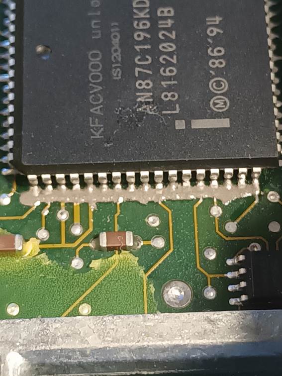
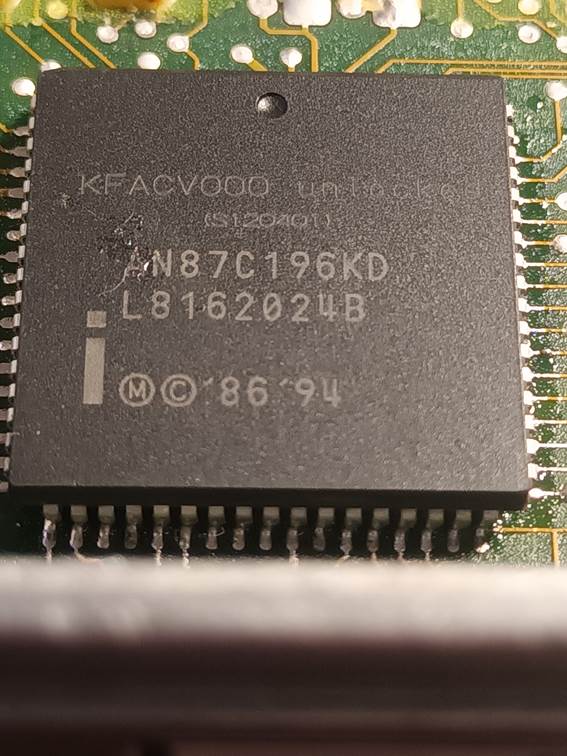
I asked Action Circuits to send me the
two chips they had programmed so that I could test them before they programmed
any more. By installing these chips on a test ECU board, I was able to verify
that the write had in fact completed normally and it was just the read
verification that had failed. I verified the chips in circuit against the
original files and everything was correct, and the chips were usable. Reading
the microcontroller data sheet, there is an override procedure by which a
programmer can verify the chip contents. This involves writing a specific
128-bit “security key”, which in fact amounts to writing back 16 bytes with the
same values already programmed; this proves that you do know what the chip
should contain, and the chip then unlocks for the duration of that power cycle.
It appears however that their programming tool did not support this mechanism.
I subsequently sent them two new files with those security bits set back to 1
and they were able to program and verify the devices, and I again got them to
send me those two devices for me to test. As expected, the security bits had no
impact on normal operation and so I asked them to program the remaining devices
using the unlocked files.
The files I used for programming the
microcontrollers are available for download here: CaterhamSuperSportEU2ECUMicrocontrollerFiles.zip.
This downloads a ZIP file containing the following:
· Caterham_7_SuperSport - Caterham - MKC103930 - KFACV000 - Locked_Original_Read.rom – This is the original read of file KFACV000.
· Caterham_7_SuperSport - Caterham - MKC103930 - KFACV000 - Unlocked_Write_Verify.rom – This is the modified KFACV000 with the security bits set back to 1.
· Caterham_7_SuperSport - Caterham - MKC103930 - KFACV001 - Locked_Original_Read.rom – This is the original read of file KFACV001.
· Caterham_7_SuperSport - Caterham - MKC103930 - KFACV001 - Unlocked_Write_Verify.rom – This is the modified KFACV001 with the security bits set back to 1.
A similar technique is used for soldering the microcontrollers. The PLCC68 package is awkward in that the IC pins wrap around underneath the chip. The contact points between the pins and the board pads are actually underneath the chip. Soldering these traditionally or even drag soldering is quite difficult as the soldering iron cannot make contact with the point where the pin touches the pad. This is especially true along the bottom edge of the chip which sits close to the casing framework which prevents access with a soldering iron at a suitable angle. It is possible but difficult to remove the board from the case, it involves splitting a re-sealing the joint around the middle of the case and the circuit board is held in place by screws which are then soldered over. Numerous power semiconductor devices are also soldered to the board and clamped to adhesive heat-conductive pads around the edge of the case too.
If you apply enough solder paste to guarantee reliable joints, it is horribly prone to forming bridges between the pins underneath the chip where they cannot be resolved, requiring the chip to be removed and the whole process to be repeated. The first technique I found which worked reasonably well was to apply a very thin strip of solder paste along the middles of the circuit boards pads where the contact points lie and initially solder the chip with hot air; and to then apply copious ChipQuik flux and drag solder over the top. The initial paste application tended to ensure that the pins and pads were wetted and connected and the drag soldering filled in the gaps to leave strong robust connections. However, I still had quite a lot of failures in the form of dry joints or (sometimes invisible) solder bridges.
My latest technique is to apply a thin bead of solder paste as above, then place the chip accurately aligned with the pads. Note the correct alignment of the dot which marks Pin 1. Ensure that you are looking vertically down on the chip when checking the alignment to avoid parallax and carefully nudged the chip into exact alignment on all edges the tip of a fine pair of tweezers or similar. The lead pitch is fine and not much misalignment can be tolerated without leading to solder bridges. The chip is then initially soldered using hot air at 220 °C using a moderate air flow. If too high an air flow rate is used, the chip position may be disturbed or the solder paste may be chased along the pins leading to excessive solder in some places and bridges between pins.
While board is still warm, thin layers of additional paste may be laid along the pins as shown. Because the board is warm, the paste melts and forms and thin and even pool rather than a bead. Hot air is applied again. This can be repeated building up the solder in the joints as required in 2 or 3 stages until they are satisfactory. Using this technique I haven’t had any troublesome bridges between pins at all.
This view shows the finished soldered joints along one side of the chip prior to cleaning.
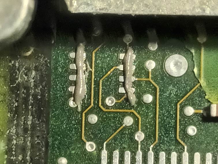
This view shows the obstruction issues with the bottom edge of the chip. It’s hard to even get a clear view of the chip pins and the contact points are out of view beneath. This makes it very hard to spot tiny solder bridges or dry joints. Drag soldering that row of pins is extremely difficult and sometimes many attempts are needed to get a satisfactory result. You cannot get a soldering in at the correct angle. Using the progressive solder paste method above seems to be a lot more reliable here.
Here is another view of the completed soldering.
And here is a view of the two chips after cleaning the circuit board with isopropyl alcohol one more time.
At this point I test every single soldered connection for continuity (using a multimeter continuity check function) between the chip pin and its board pad. Along the bottom edge I use a curved needle as probe to contact the PCB pads and traces without touching the IC pins. I also check every pair of adjacent pins for continuity to detect unseen solder bridges. Note that pins 3 and 4 are bridged by design by printed circuit board traces, but no other adjacent pairs of pins should be shorted.
At this point the ECU is tested on the bench harness using MEMS3 Mapper and should operate normally.

The waterproof conformal silicone coating on the circuit which was stripped for soldering now needs to be repaired. I used the coating sown below which can be applied using the brushes provided in the kit.
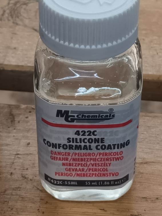
Be sure to overlap the edges of the old silicone conformal coating to ensure a good seal. The coating contains an ether solvent which flashes off quite quickly, the silicone then takes a few hours to cure.
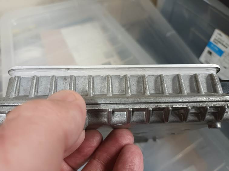
Once the conformal silicone has cured, a thin bead of grey RTV silicone is run around the top lip of the casing.
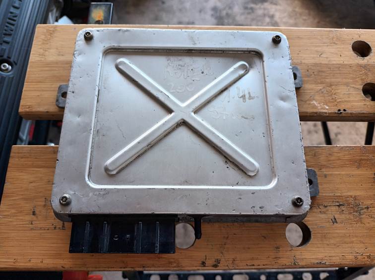
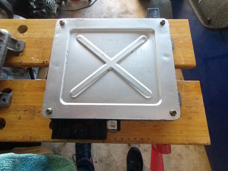
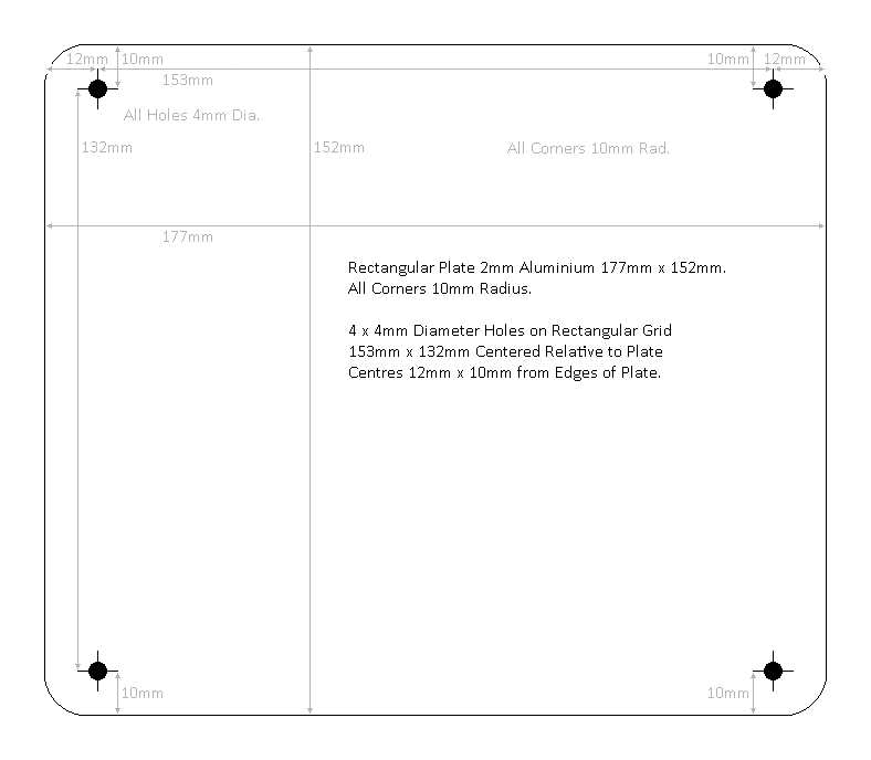
A replacement lid is laser cut according to the design shown below. The original lid wraps over the edges of the ECU to give a wider sealing area. To compensate for the thin sealing track, the replacement lids are cut from 2mm thick aluminium for rigidity and are cut to overhang the edge of the ECU by approximately 3mm on each side, allowing a second thicker bead of silicone to be run around the outside of the lid once the first bead has cured.
The replacement lid is then installed using the original bolts. Care needs to be taken not to over-tighten the bolts. The additional thickness of the replacement lids means that the thread engagement is limited and applying too much torque could strip the threads. The bolts only need to be tight enough to hold the lid securely in place.
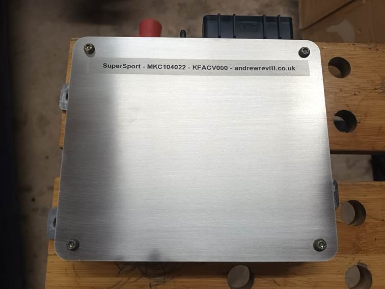
Once the first RTC silicone bead has cured, the lid is sealed around the outside under the overhang with a second layer of RTV silicone which can be spread and smoothed with a finger.
That completes the conversion.
Installation
Instructions
The following instructions cover everything you need to do to install the new ECU and get it up and running in your car:
1. Switch the ignition off.
2. Unplug the connector from the front of the old ECU. There is a plastic tab on the front top edge of the connector that needs to be pressed downwards before it can be withdrawn.
3. Carefully pull the MAP vacuum line off the nipple on the front of the old ECU. Be careful to pull it straight, the plastic nipples are easily cracked or broken. It may help to twist the pipe.
4. Remove any securing fasteners and remove the old ECU.
5. Position the new ECU and secure with the fasteners removed above.
6. Carefully press the MAP vacuum line onto the plastic nipple on the front of the new ECU. Again, be careful not to bend the plastic nipple as they break easily.
7. Push the connector home until it latches into place.
8. Turn on the ignition. Verify that the fuel pump primes as expected.
9. Calibrate the new ECU to the closed throttle voltage of the installed TPS. If this is not done the engine will struggle to idle correctly. The process is:
a. Start with the ignition off.
b. Turn the ignition on but do not start.
c. Smoothly open the throttle to full and close it back to the idle stop 5 times.
d. Turn the ignition off for 10 seconds.
10. Pair the new ECU with the installed immobiliser. If this is not done the engine will be immobilised and will die after 2 seconds of running. This may be performed using one of various tools. Choose one of the methods listed below.
o Pair the ECU and immobiliser using MEMS3 Mapper (on a Windows PC).
§ Connect a VAG COM KKL 409.1-style cable to the diagnostic port on the car. These can be obtained easily and cheaply on eBay. I am happy to supply a suitable cable with the ECU if you want one.
§ Download the latest version of my FREE MEMS Tools: Download Link: https://andrewrevill.co.uk/Downloads/MEMS3Tools.zip
§ Extract the entire contents of the downloaded ZIP file into a new, empty folder on your hard drive.
§ In that folder, double click the file MEMS Mapper - For All Regular ECUs.exe to launch MEMS3 Mapper.
§ Connect the OBDII cable to your computer. Look for the hint that pops up briefly in the top right-hand corner telling you the COM port number for the new device.
· If this isn’t displayed, you may need to install one or other of the drivers for your cable. The drivers are usually supplied on a CD, or available to download from the seller of the cable, or may be found in the OBDII Cable Drivers folder within MEMS3 Tools.
§ Select the correct COM port in the drop-down box in the top right-hand corner of MEMS3 Mapper.
§ Select the ECU type Rover MEMS 1.9 in the drop-down box in the top right-hand corner of MEMS3 Mapper.
§ Turn the ignition on.
§ Click the About ECU button to confirm you have a connection to the ECU.
§ Select Tools | ECU Tools | Learn Immobiliser Code from the main menu. Check that the message displayed confirms that a new immobiliser code was learned.
§ Turn the ignition off for 10 seconds.
o OR Pair the ECU and immobiliser using a PScan device.
o OR Pair the ECU and immobiliser using a T300+ device.
Adaptation
After installation the ECU will be in a factory virgin state. All adaptations will be reset to default values. The ECU will need some driving time to adapt to the characteristics of the engine.