MEMS3 & Sharpening the VVC
Response
Download
Link: https://andrewrevill.co.uk/Downloads/MEMSTools.zip
Making the VVC mechanisms respond
more quickly.
I was recently contacted by somebody with an Elise with a MEMS3 VVC 160 engine from an MGF Trophy. He was suffering from a lack of top end power. As I was on holiday at the time I couldn’t really look at much, but I did get him to use the high speed data logging facility in MEMS Mapper and send me the logs so I could see if anything looked obviously wrong. Something didn’t seem right. To cut a long story short, it was actually quite normal for the standard VVC engine and nothing to do with the problem at hand, but still something I wanted to look at.
THE ISSUE
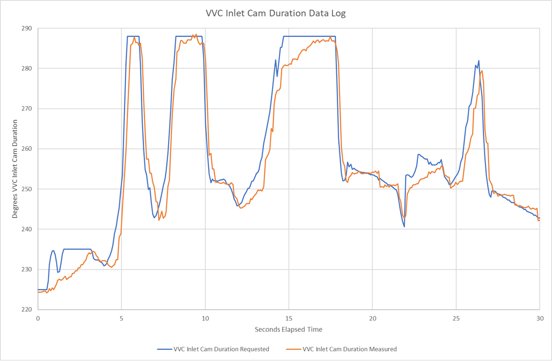
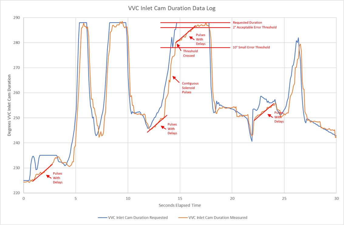
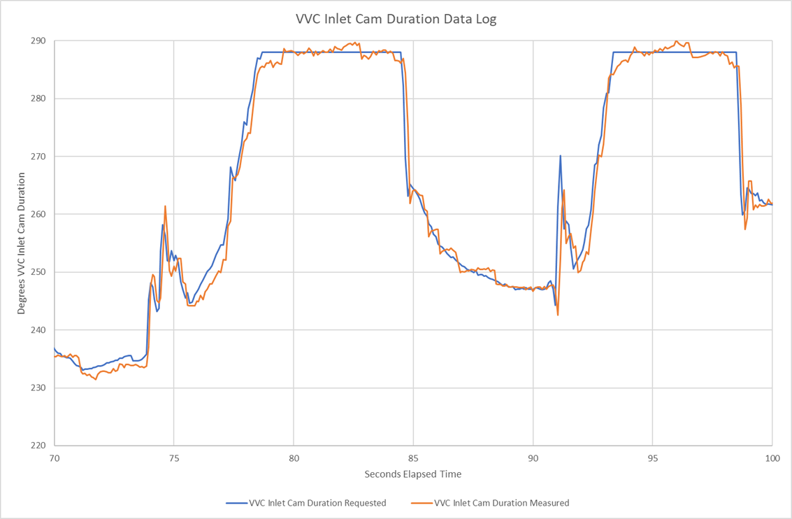
The graphs below illustrates what I was seeing. The blue line represents the requested VVC inlet cam duration, that is the inlet cam duration that the ECU was trying to achieve. The orange line represents the measured VVC inlet cam duration, that is the inlet cam duration that the ECU was measuring using the signal from the cam position sensor. As you can see, when the ECU was demanding a large deployment of the VVC mechanisms, they were very sluggish in reaching their target duration. The initial response was rapid, but they then crawled slowly open to their final position over 3 to 4 seconds. Especially in the lower gears when the engine speeds and demands may change rapidly, this meant that the VVC system was lagging well behind the demand and was not delivering optimum torque.
When I got back from my holiday, I set about data-logging my own car. My engine has only done a low mileage since built with a full set of brand-new VVC mechanisms, including all of the hydraulics, so I had no reason to believe that mine would be sticking or sluggish. But the results were pretty much EXACTLY the same. In fact, the graph below is from my car. This got me thinking that this must be the built-in behaviour f the VVC ECU in some way.
INVESTIGATIONS
I set about investigating what was going on in two ways.
Firstly, I used my Research Engine Simulator. This is a big project that I still have to write up and publish, but basically it’s a box of microprocessor-controlled electronics that connect up to the ECU and simulator the behaviour of the complete engine. This includes mathematical models of the MAP and the VVC mechanisms. The ECU just doesn’t know it’s not actually running an engine, it runs completely normally without logging DTCs. Crucially it allows me to run the ECU through any scenario that I could set up on the road, but I can run the same scenario repeatedly, exactly the same every time, on the bench. I can simulate idling, misfires, rev limiter, overrun, pretty much anything. In this case I ran it through a simple scenario of ramping the throttle open to 90% over 0.5 seconds and ramping the RPM parabolically up to 7000rpm over a few seconds, holding it, then closing the throttle and dropping back to idle. The simulator monitors the ECUs solenoid drive pulse outputs (it has big load resistors to convince the ECU it’s connected to real solenoids) and models the response of the physical mechs. And guess what the results looked like?
OK so my mathematical model of the VVC mechs is not quite accurate and the slow ramp was a little less obvious in reality, but the same effect was clearly there and it was clearly being driven by the ECU rather than being an issue with the mechs.
Secondly, I started reverse-engineering all of the ECUs VVC mech control code, to see what strategies it was using to drive the mechs.
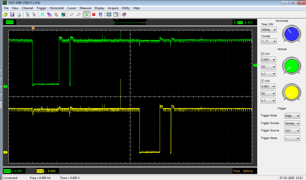
The screenshot below shows what you I had normally been seeing when forcing the VVC mechs to make a step change. The green trace is the drive to the VCC INCREASE solenoid, the yellow trace is the drive to the VVC DECREASE solenoid. In each case you get one long pulse which seems to drive the mechs most of the way, followed by one or more of short correction pulses which close in on the target:
Initially the code didn’t make a lot of sense. I found one table of time delays which seemed to drive the long pulse width, and another which seemed to drive the short pulse width, but they were the wrong way around in the code. It was using the “long” pulse widths for small errors when it was close to target and the “short” pulse width initially. I couldn’t find any fault in my logic. Eventually I realised that I was thinking about it all wrong …
THERE IS NO LONG PULSE!
It’s actually just a stream of the short pulses with no gaps between them. When I ran a more realistic scenario on the engine simulator, rather than just modifying the map to force a sudden step change to look at, I saw this, which makes it quite a bit clearer:

The way it works in code is this:
· The ECU compares the measured VVC inlet cam duration with the requested duration.
· If the absolute error is less than 2° (set by a scalar in the map), it regards it as acceptable and does nothing. This prevents it hunting backwards and forward over tiny errors.
·
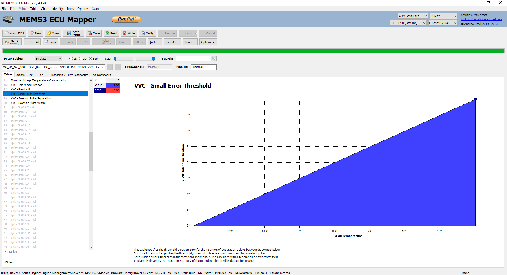
If the error is greater than a certain
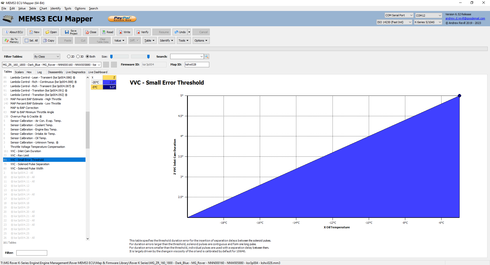
threshold, which is 10° when hot but set according to oil temperature by this
table …
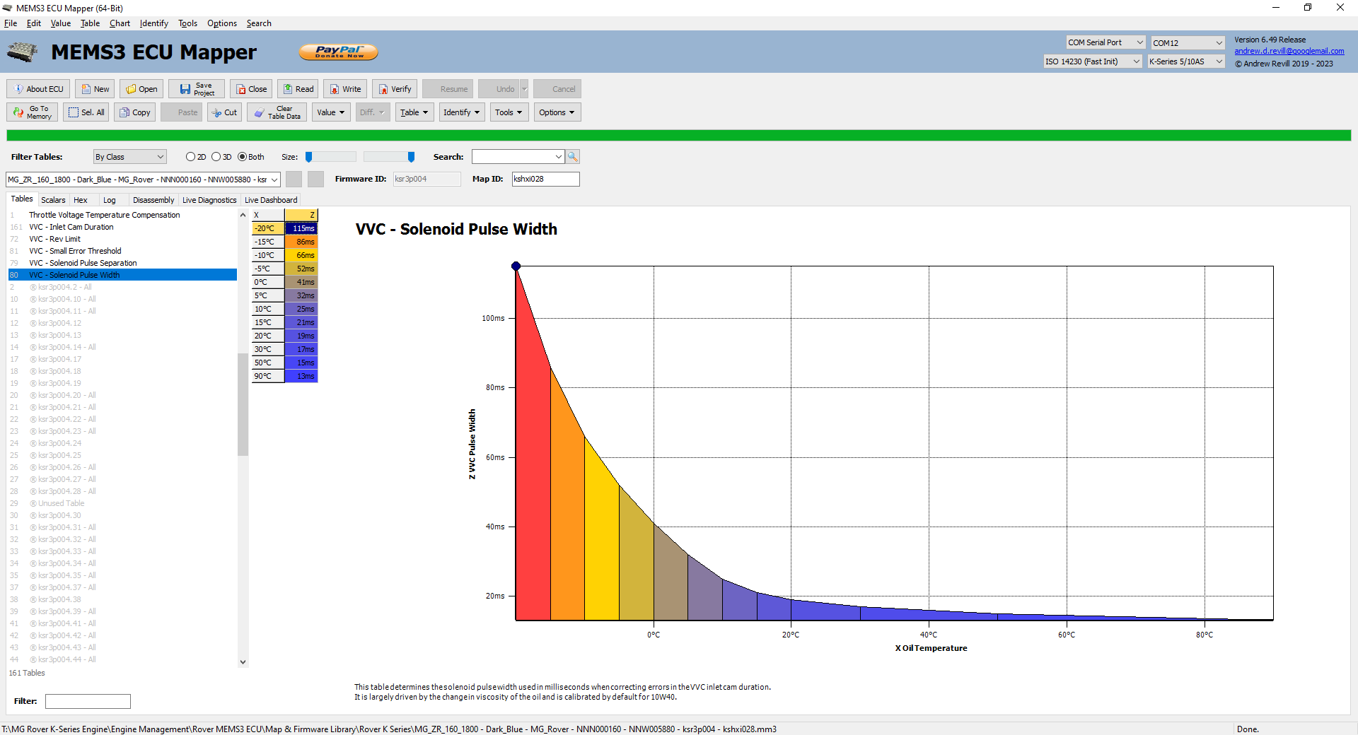
… then the ECU immediately drives the relevant solenoid, and sets a countdown
timer to the relevant pulse width, which is typically 13ms when hot but set
according to oil temperature by this table:
Nothing further happens until the countdown timer expires.
·
If the error is between these values, the ECU
sets a delay countdown timer to a delay period, typically 170ms when hot but
set according to oil temperature by this table:
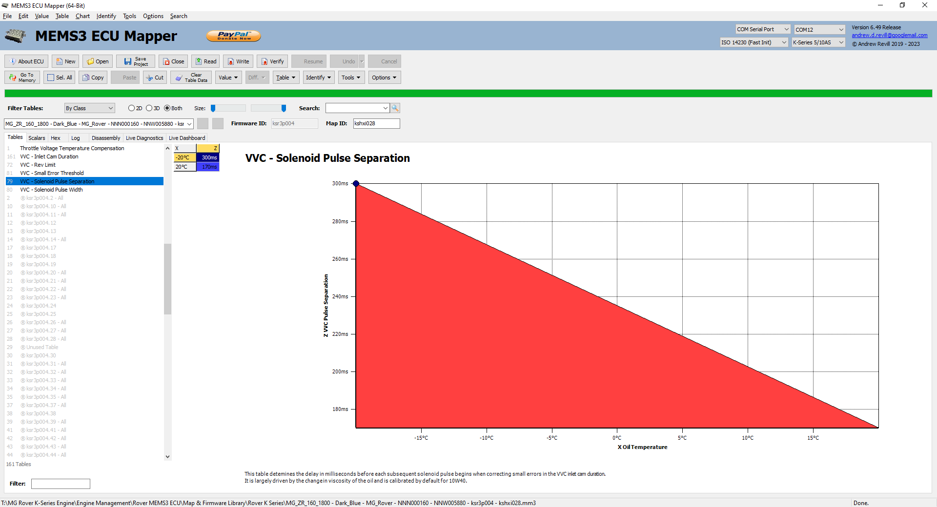
Only once the delay period has expired will it allow another solenoid pulse.
Armed with this understanding, it was clear what was happening. I’ve repeated the original log chart below and annotated it with what’s going on. You can clearly see that when the demand increases, the mechs are driven by a series of closely spaced pulses which drive them open rapidly, but once the 10° error threshold is release the ECU slows the drive down by inserting delays between the pulses. Once the 2° error threshold is release the ECU stops driving the mechs.
IMPROVEMENTS
From the above, this behaviour is clearly by design. I think the idea is to ensure that under the worst-case conditions, the VVC mechs don’t start overshooting the target duration and oscillating backwards and forwards, hunting to find the target. Within 10° duration of the target, the ECU makes a change and then allows a pause for the mechs to settle before measuring again and making a further change if necessary.
From the testing I’ve done (which has now involved a grand total of three engines – and a simulator), the mech response programmed does seem to be extremely conservative and there does appear to be considerable scope to tighten it up without causing any problems.
On my car, I made the following map changes:
·
I increased the pulse width slightly. Given that it would take a lot of
testing to verify the behaviour at all temperatures, and given that we
shouldn’t be pushing these engines too hard until warmed up, I decided to only
adjust numbers at the higher end of the temperature scale. If it's driving out
a pulse every 183 milliseconds (13ms pulse width pulse 170ms delay) and closing
the 10° gap over 2.1
seconds that's 11 or 12 pulses, so just under 1 degree adjustment per pulse (my
guess is they were targeting 1° per pulse). That sort of sounds reasonable to avoid overshoot with a 2° tolerance deadland either side (4° total), but it could probably afford to
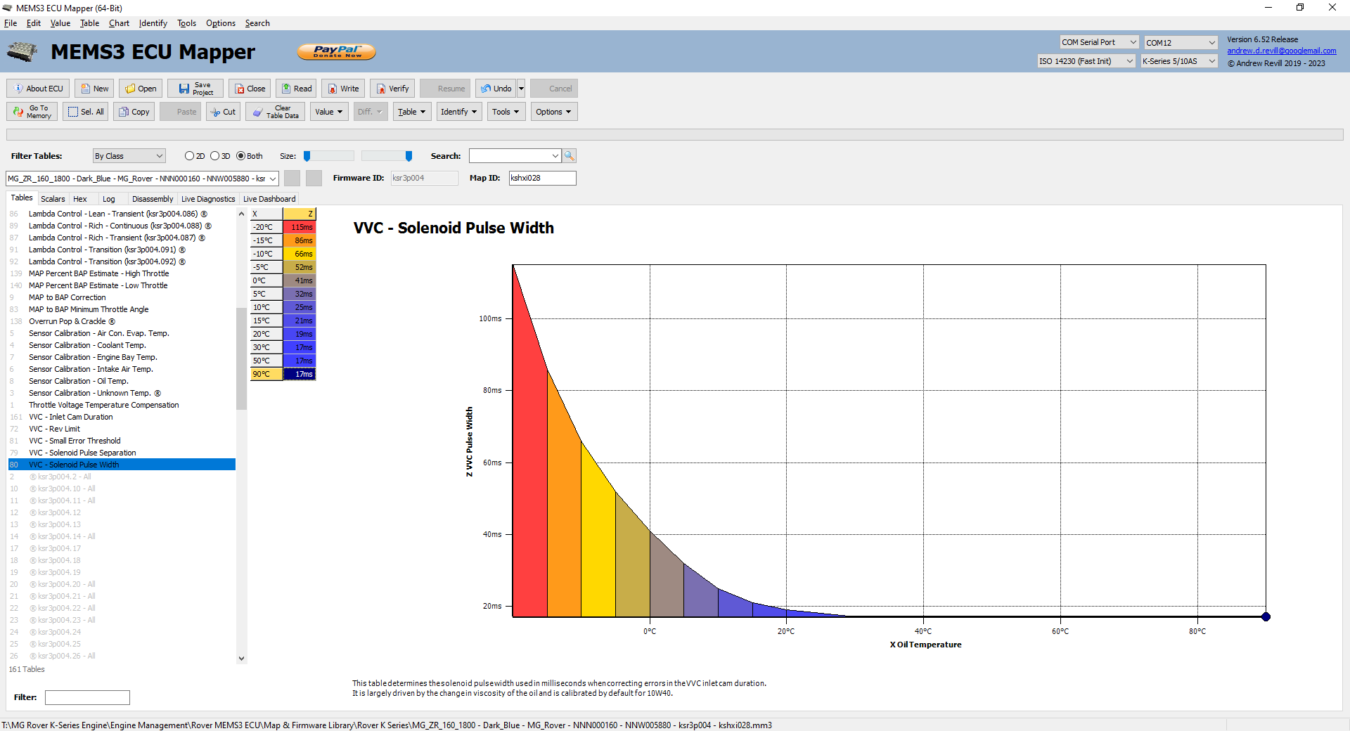
drive a bit faster and still avoid hunting. I therefore increase the pulse width
above 30°C to maintain a
minimum of 17ms instead of decaying it further to 13ms. This is a 30% increase
in the pulse width and step size on a hot engine. This should still leave 2 or
3 step positions withing the desired deadband.
·
I reduced the “small error” threshold from 10° duration to 5° duration when the engine was hot. By default, this
ramps up from 2° duration at -20°C to 10° duration at 20°C, passing through
5° duration at -5°C. I capped this at 5° duration:
THE RESULTS
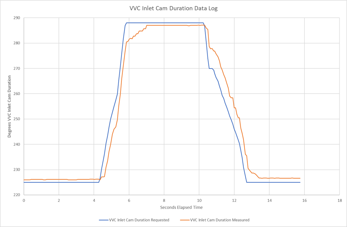
Below is a data
log from my car with the above changes. As you can see, the tracking of the
requested VVC inlet cam duration is much more accurate. There is much less time
spent with the mechanisms deployed significantly below the position for optimum
performance specified in the map. There’s nothing to suggest tat it’s hunting
or misbehaving. What you can see is that at maximum deployment, the VVC
mechanisms have a slight tendency to drift open with the engine rotation over a
period of about 4 second and so the ECU gives an occasion downward pulse to
keep them in place. You don’t see that on the original log because the mechs
were not pinned at maximum deployment for long enough, but I’ve since verified
(by loading it up for longer periods in higher gears) that this does happen
with the standard settings and isn’t an effect of the changes made.
On the road
it’s always hard to be sure what you can feel, especially when you’re expecting
particular changes. But I’m fairly sure that especially in the lower gears it
feels sharper and more responsive, with a more immediate shove in the back when
you floor it – and more wheelspin!