Recovering a Bricked Rover MEMS3 ECU – Without
Opening the Case
Download
Link: https://andrewrevill.co.uk/Downloads/MEMSTools.zip
NOTE: THIS DOCUMENTATION IS UP TO DATE AS OF VERSION 4.90 RELEASE OF
THE MEMS3 TOOLS APPLICATION SUITE.
In the latest releases of my MEMS Mapper tool I have gone to
great lengths to try to ensure that ECUs cannot be accidentally bricked by
writing bad firmware or map to the ECU. However, there are some things that I
just cannot protect against, for example the user manually editing the memory
bytes in the hexadecimal editor to produce something that is not valid, or
writing a firmware to hardware that just cannot support it. The small but
non-zero risk of bricking an ECU has always bothered me. Whilst researching
these ECUs I’ve bricked many, and the only way to recover them so far has been
to open them up, de-solder the main EEPROM chip using hot air, reprogram the
EEPROM with valid firmware and map using an EEPROM programmer on the bench and
then solder the chip back in, which is tedious and time-consuming problem and
not exactly good for the board and other components.
I always suspected that the engineers who designed it would have
left a back door in somewhere to allow a bricked ECU to be recovered.
Bricked
ECUs
In addition to the firmware and map, the EEPROM chip contains a
boot loader program. When a brand new virgin ECU is suppled, the boot loader is
all that is present. The boot loader has sufficient functionality to allow the
ECU to communicate with a programmer and load the firmware and map. The boot
loader generally checks to see whether valid firmware and map are present and
if so, shortly after the ECU boots it transfers control straight to the
firmware. The boot loader initialises watchdog timers which reboot the ECU if
the firmware appears to have hung up, and what generally seems to happen in the
case of a bricked ECU is that the boot loader sets up the watchdogs, transfers
control to the firmware which fails to operate normally, the watchdogs detect
this and reboots the ECU which then just repeats the same cycle. The ECU is
stuck in an indefinite boot loop. You usually see the fuel pump starting to
prime then being switched off again several times a second forever. Because the
ECU is constantly rebooting, you never get the chance to establish stable
communications with it so cannot even begin to reprogram it with valid firmware
and map.
The boot loader code is protected and permanent. It is loaded into
the first sector of the EEPROM chip at manufacture and the ECU does not appear
to provide any method to erase or modify it. Certainly my MEMS Mapper and
Flasher tools never touch the boot loader in an ECU. This means that whatever
we do to the firmware and map, however badly we screw those up to brick the
ECU, the boot loader will still be clean and valid and just the way it was the
day the ECU was manufactured.
If only I could find some way to prevent the boot loader from
transferring control to the firmware, as though no firmware had been loaded …
Back Door
Search
I decided to search for a possible back door by working through a
disassembly of the boot loader code. Now I’ve spent quite a long time looking
at disassembled code from the ECU in the past and I have to say it’s not been
anywhere near as successful as I would have hoped. The code is very opaque and
difficult to get into. But I thought that if I was searching for the answer to
a very specific question I might stand a chance, and in this case I had few
pointers to help me get started. For example, once the boot loader jumps into
the firmware, the firmware mostly executes as a separate stand-alone program.
The boot loader should be independent of the firmware, so there are very few
references to firmware addresses in the boot loader code and any references
that I did find were likely to be related to the process of checking for loaded
firmware and launching the firmware.
Back Door
Analysis
The analysis below is based on a disassembly of the VVC 160 ECU
NNN000160’s boot loader “bootp033” but the code varies very little across
different boot loaders.
Subroutine $001007CA is
responsible for jumping into the firmware (at addresses $001007D8, $001007DE and
$001007E2). It loads the address of
the firmware $110000 into register a0, offsets that by 4 bytes and reads the
vector at that address to put the firmware entry point into register a0, then
jumps to the address that register a0 points to:
ROM:001007CA
ROM:001007CA ; =============== S U B R O U T I N E
=======================================
ROM:001007CA
ROM:001007CA
ROM:001007CA sub_1007CA: ; CODE XREF:
ROM:00100622↑p
ROM:001007CA btst #0,d1
ROM:001007CE bne.s loc_1007E6
ROM:001007D0 cmpi.l #0,d0
ROM:001007D6 bne.s
loc_1007E6
ROM:001007D8 movea.l
#dword_110000,a0
ROM:001007DE movea.l
4(a0),a0
ROM:001007E2 jmp (a0)
ROM:001007E4 ;
---------------------------------------------------------------------------
ROM:001007E4 bra.s locret_1007EA
ROM:001007E6 ;
---------------------------------------------------------------------------
ROM:001007E6
ROM:001007E6 loc_1007E6: ; CODE XREF:
sub_1007CA+4↑j
ROM:001007E6 ;
sub_1007CA+C↑j
ROM:001007E6 bsr.w sub_1007F8
ROM:001007EA ;
---------------------------------------------------------------------------
ROM:001007EA
ROM:001007EA locret_1007EA: ; CODE XREF: sub_1007CA+1A↑j
ROM:001007EA rts
ROM:001007EA ; End of function sub_1007CA
ROM:001007EA
Before executing the firmware, it performs a couple of tests.
Specifically it tests that both bit 0 of register d1 is 0 (at addresses $001007CA and $001007CE) and register d0 contains 0 ($001007D0 and $001007D6)
when the subroutine is called. The firmware is only executed if both of these
tests are passed.
Subroutine $001007CA
above is called right at the end of the main entry point routine of the boot
loader. Before calling $001007CA
this calls other boot loader subroutines $00100628,
$00100708, $00100740 and $001007A2:
ROM:00100612
ROM:00100612 loc_100612: ; CODE XREF:
ROM:00100576↑j
ROM:00100612 bsr.w
sub_100628
ROM:00100616 bsr.w sub_100708
ROM:0010061A bsr.w sub_100740
ROM:0010061E bsr.w sub_1007A2
ROM:00100622 bsr.w sub_1007CA
ROM:00100626
ROM:00100626 locret_100626: ; CODE XREF:
ROM:00100610↑j
ROM:00100626 rts
ROM:00100628
Subroutine $00100740
checks for the $5AA5 signatures of the firmware (at firmware address $110410, in code starting at address $00100752) and map (at map address $13C012, in code starting at address $0010075E) (you can look at these
addresses in any valid firmware and map using MEMS Mapper and see that they do
indeed always contain the signature bytes $5AA5) and sets bits in register d0
if they are not found, so the check for register d0 being 0 amounts to a check
that firmware and map are loaded.
ROM:00100740
ROM:00100740 ; =============== S U B R O U T I N E
=======================================
ROM:00100740
ROM:00100740
ROM:00100740 sub_100740: ; CODE XREF: ROM:0010061A↑p
ROM:00100740 movea.l
#dword_110000,a0
ROM:00100746 clr.l d0
ROM:00100748 cmpi.w #0,d7
ROM:0010074C bne.s loc_100752
ROM:0010074E bset
#1,d0
ROM:00100752
ROM:00100752 loc_100752: ; CODE XREF:
sub_100740+C↑j
ROM:00100752 cmpi.w #$5AA5,$410(a0)
ROM:00100758 beq.s loc_10075E
ROM:0010075A bset #0,d0
ROM:0010075E
ROM:0010075E loc_10075E: ; CODE XREF:
sub_100740+18↑j
ROM:0010075E movea.l
#word_13C000,a0
ROM:00100764 cmpi.w #$5AA5,$12(a0)
ROM:0010076A beq.s loc_100770
ROM:0010076C bset #2,d0
ROM:00100770
ROM:00100770 loc_100770: ; CODE XREF:
sub_100740+2A↑j
ROM:00100770 movea.l
#unk_110400,a1
ROM:00100776 movea.l
#word_13C00A,a0
ROM:0010077C move.b
#0,d2
ROM:00100780 bra.s loc_100786
ROM:00100782 ;
---------------------------------------------------------------------------
ROM:00100782
ROM:00100782 loc_100782: ; CODE XREF:
sub_100740+5E↓j
ROM:00100782 addi.b #1,d2
ROM:00100786
ROM:00100786 loc_100786: ; CODE XREF:
sub_100740+40↑j
ROM:00100786 cmpi.b #7,d2
ROM:0010078A bgt.s locret_1007A0
ROM:0010078C move.b
(a1),d1
ROM:0010078E cmp.b (a0),d1
ROM:00100790 beq.s loc_100796
ROM:00100792 bset #3,d0
ROM:00100796
ROM:00100796 loc_100796: ; CODE XREF:
sub_100740+50↑j
ROM:00100796 adda.w #1,a0
ROM:0010079A adda.w #2,a1
ROM:0010079E bra.s loc_100782
ROM:001007A0 ;
---------------------------------------------------------------------------
ROM:001007A0
ROM:001007A0 locret_1007A0: ; CODE XREF:
sub_100740+4A↑j
ROM:001007A0 rts
ROM:001007A0 ; End of function sub_100740
ROM:001007A0
ROM:001007A2
So we now know that the firmware will be executed if both firmware
and map are loaded and bit 0 of register d1 is 0 when subroutine $001007CA is called. We also know from
previous experience that when an ECU does not have firmware or map loaded, it
happily runs the boot loader and allows normal programming over OBDII using the
MEMSMapper application. Looking at the code, I would expect identical
behaviour if the other test failed, i.e. if bit 0 of register d1 is 1 when
subroutine $001007CA is called. So
if we can find a way of setting this bit at this point, we should have a way of
preventing the ECU from executing the firmware and accepting programming just
as though it was a virgin ECU, and that would be the
back door we were looking for.
So what is bit of 0 of register d1 doing?
Subroutine $001007A2,
which is called in the boot loader immediately before the signature checking
routine $00100740 above, manipulates
bit 0 of d1, and so it determining the other requirement for the firmware to be
executed. It’s a very simple subroutine which sets bit 0 of d1 entirely based
on registers of the QSM (Queued Serial Module) in the MC68336 microcontroller:
ROM:001007A2
ROM:001007A2 ; =============== S U B R O U T I N E
=======================================
ROM:001007A2
ROM:001007A2
ROM:001007A2 sub_1007A2: ; CODE XREF:
ROM:0010061E↑p
ROM:001007A2 btst #6,($FFFFFC0D).w
ROM:001007A8 beq.s loc_1007C4
ROM:001007AA cmpi.b #$96,($FFFFFC0F).w
ROM:001007B0 bne.s loc_1007C4
ROM:001007B2 bset
#0,d1
ROM:001007B6 bset #0,($FFFFFC0B).w
ROM:001007BC bclr #0,($FFFFFC0B).w
ROM:001007C2 bra.s locret_1007C8
ROM:001007C4 ; ---------------------------------------------------------------------------
ROM:001007C4
ROM:001007C4 loc_1007C4: ; CODE XREF:
sub_1007A2+6↑j
ROM:001007C4 ;
sub_1007A2+E↑j
ROM:001007C4 bclr #0,d1
ROM:001007C8
ROM:001007C8 locret_1007C8: ; CODE XREF:
sub_1007A2+20↑j
ROM:001007C8 rts
ROM:001007C8 ; End of function sub_1007A2
ROM:001007C8
ROM:001007CA
If bit 6 of QSM register SCSR is 0 (tested at addresses $001007A2 and $001007A8) then bit 0 of register d1 is cleared to 0 (at address $001007C4), otherwise if the low byte
of QSM register SCDR is not $96 (tested at addresses $001007AA and $001007B0)
then bit 0 of register d1 is also cleared to 0 (at address $001007C4), otherwise bit 0 of d1 is set to 1 (at address $001007B2), bit 0 of QSM register SCCR1
is toggled to 1 then 0. The subroutine then exits in all cases.
Now the SCSR register is the SCI Status Register and SCDR register
is the SCI Data Register, and the SCI is the Serial Communications Interface
which is part of the QSM. It is basically a standard UART serial port. SCSR
tells us about the current status of port operation and SCDR holds the most
recent byte received. From the MC68336 data sheet, Bit 6 of the status register
SCSR is the RDRF flag, or Receive Data Register Full – it tells us if there’s
something in the data register SCDR.
So the condition which determines that a loaded firmware should be
executed is simply that no byte has been received by the SCI port, or that byte
was not $96.
In other words, we can prevent any loaded firmware being executed
by sending the byte $96 to the SCI port at the right moment.
That leaves three questions:
1)
What is the right moment?
2)
What is the SCI port connected to?
3)
What Baud rate should we transmit the $96 at?
The answer to question 1 is clearly “as the ECU boots”, but
exactly when during the boot sequence is not easy to determine, so I decided to
try the approach of just broadcasting the byte $96 continuously as the ECU was
powered on. I couldn’t be sure this would work but it was certainly worth a
try.
The answer to question 2 seemed likely to be the OBDII serial
port. My guess was that SCI was just connected to the OBDII K-Line as this was
used for serial UART communications with the ECU. It would be extremely
convenient if this turned out to be the case as I could provide a utility
within MEMS Mapper that just broadcast $96 to the OBDII port while you powered
the ECU on. Again, I couldn’t be sure
this was the case without a lot more digging in the firmware disassembly or
tracing the electronics, but the easiest thing was to give it a try.
As for question 3, one of the subroutines called immediately prior
to those discussed above by the boot loader was $00100628, and that contained the following lines:
ROM:0010069E
ROM:001006A0 ;
---------------------------------------------------------------------------
ROM:001006A0
ROM:001006A0 loc_1006A0: ; CODE XREF:
ROM:0010051A↑j
ROM:001006A0 move.w #$34,($FFFFFC08).w ; '4'
ROM:001006A6 move.w #$C,($FFFFFC0A).w
ROM:001006AC bra.l loc_100520
ROM:001006B2 ;
---------------------------------------------------------------------------
ROM:001006B2
These load the SCCR0 register of the QSM with the value $34 (at
address $001006A0). SCCR0 is the SCI
Control Register 0 and controls the Baud rate at which the SCI port operates,
according to the formula Baud Rate = (Clock Frequency) / 32 / SCCR0. So with a
system clock frequency of 16Mhz and an SCCR0 value of $34 or 52 decimal, the
Baud rate was configured to 16000000 / 32 / 52 = 9615, which is as close as you
can get to the standard OBDII Baud rate of 9600 Baud. This provided even more
evidence that I was on the right lines thinking that the SCI port was actually
the OBDII K-Line.
So my plan was to broadcast $96 at 9600 Baud over the OBDII port
while booting up the ECU and … rather to my surprise, it worked! That’s the back door I was looking for.
So that
provides a failsafe way of being able to recover a bricked ECU. I’ve
tested using it to prevent a perfectly healthy ECU from executing the firmware
- the ECU just sits in boot / programming / recovery mode in the boot loader
waiting to be programmed. I’ve tested communications with the ECU after
blocking the firmware with this signal and all seems normal. Finally I’ve used
to unbrick a development ECU that got bricked while I was playing with it. I’m
pretty much 100% sure that this method will unbrick any MEMS3 ECU that has bad
firmware or map as the boot loader code is protected and always virgin. It
doesn’t matter how the ECU was bricked, whether it was using MEM3 Flasher /
Mapper or other programming tools such as Galletto, this method provides a safe
recovery option.
Recover
Bricked ECU
In release 4.87 of MEMS Flasher and MEMS Mapper I’ve now added
an option to the ECU Tools menu to Recover Bricked ECU. When you select
this option, the application will begin to broadcast the request code at
regular intervals and monitor for the expected response. If the ECU is stuck in
a boot loop, constantly rebooting, it should recover almost immediately as the
next time it reboots it will detect the request and remain in the boot loader
ready to accept programming. If the response is not detected within a short
time, the following dialog is displayed:
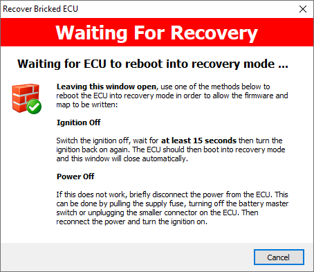
If the ECU is hanging and unable to communicate, we need to
persuade it to reboot. Switching the ignition off for at last 15 seconds (and
then back on again) is usually sufficient to ensure that it will perform a full
boot when powering on again. At this point it should again remain in the boot
loader ready to accept programming as above. If the ECU was really tightly
stuck in a loop, then just occasionally switching the ignition off is not
sufficient to break it out of the loop and trigger a reboot. In this case, you
need to briefly remove power from the ECU. When power is re-applied and the
ignition is turned on it will boot again, detect the request and remain in the
boot loader ready to accept programming as above.
Depending on the timing of the request code, it may occasionally
require more than one attempt to recover an ECU.
When the expected response is detected, the following dialog is
displayed:
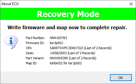
Once the ECU has recovered into a state where it is running the
boot loader and willing to communicate with the application again it is
important that you then write a good replacement firmware, map or both
(depending on what was damaged, if in doubt do both). The initial recovery is
only temporary; we have broken the ECU out of the cycle that was preventing it
from communicating and accepting programming using the special code, but next
time it reboots without seeing the request broadcast it will of course continue
to try to execute the damaged firmware or map as before. In recovery mode, some
of the ECU tools and operations will fail (the ECU will reject the operations
as it will not be running the firmware) and it will not provide any engine
management functionality, but everything necessary to read and write the
firmware and map will function normally.
Once you have rewritten the ECU the repair will be permanent.