MEMS3 Map Switching on Very Tight
ECUs – Enables Map Switching on MG ZT Turbo
Download
Link: https://andrewrevill.co.uk/Downloads/MEMSTools.zip
Using my MEMS Mapper you can now
reduce map and firmware sizes to allow map switching on ECUs with very little
free space.
I
was recently asked to looked at extending my dual-map live-switching system to
cover Land Rover Freelander ECUs. These were unable to implement the original
solution due to lack of free firmware EEPROM space. I wrote this up here: MEMS3
Extended Firmware Memory Map. Unfortunately, the techniques I developed
there were still insufficient to allow dual map switching on an MG ZT turbo
ECU. These ECUs have so little spare firmware space and such large maps that
even with the additional 8kB released in that article, there was not enough
space to fit a second map in the firmware area.
It is, however, still (just) possible to get two maps
and the switching code installed onto these ECUs, using all of the following
techniques. These are now fully supported in MEMS Mapper Version 7.45
Release or later.
·
Rearranging the memory map to gain an additional 8kB
of firmware space, as described previously.
·
Deleting the configuration template from the
firmware. Tools | Wizards | Delete Config Template.
·
Enabling variable-length maps. Tools | Wizards |
Variable Length Map.
·
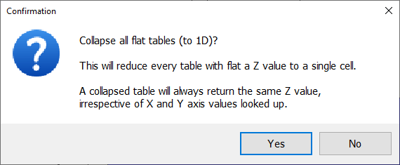
Collapsing all flat tables to single cells. Tools
| Map Maintenance | Collapse All Flat Tables.
·
Collapsing the Sensor Calibration - Ambient Air
Temp. table. Table | Collapse Table (to 1D).
·
Collapsing the Sensor Calibration - Air Con.
Evap. Temp. table. Table | Collapse Table (to 1D).
·
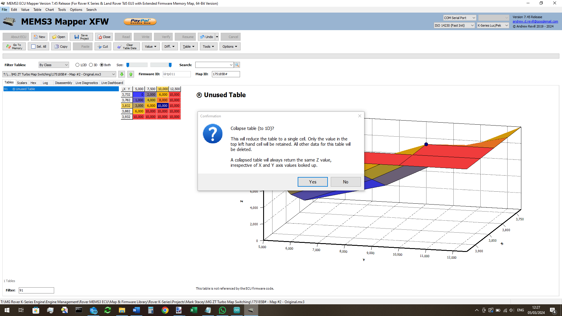
Collapsing the Unused Duplicate Air Conditioning Table.
Table (Table 91 in klrtp011). Table | Collapse Table (to 1D).
·
Compacting the map table space. Tools | Map
Maintenance | Compact Table Space.
·
Changing the map length to the minimum possible
value. Tools |Map Maintenance |Change Map Length | Use Minimum.
·
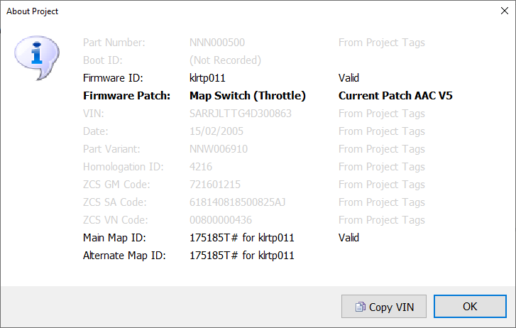
Installing the map
switching patch. Tools | Project Tools | Install Map Switch Patch (Any
EXCEPT Coolant).
I’ll take each of
these in turn:
· Rearranging the memory map to gain an additional 8kB of firmware
space.
As described here: MEMS3
Extended Firmware Memory Map. This releases the largest single increase in
available space and is absolutely necessary as a first step. Remember that once
this step has been performed, you need to use the Extended Firmware Memory Map
(XFW) build of MEMS Mapper for all of the remaining steps.
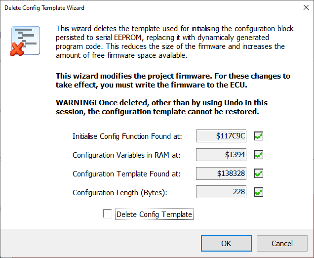
· Deleting the configuration template from the firmware.
At the end of the firmware, after the end of the executable
code, there is a block of data. This is mostly blank ($00 bytes) and consists
of two separate areas:
o
A clean blank copy of the ECU’s persistent
configuration, which is normally save to serial EEPROM in 2 copies for
robustness. This includes things that can change at run time (rather than as
part of ECU programming) such as the immobiliser code, diagnostic information
and the long term fuel trims.
o
Another block of data. Mostly just $00, which is not
referenced at all by the ECU code. It appears that the compiler allocated a
block of data for constants, which was only partially used by the configuration
template.
The configuration template itself consists most of:
o
A lot of $00 bytes.
o
A block of (usually) 81 consecutive
$7D bytes. These are the default long term fuel trim table, byte-sized, 9x9.
o
A small number of other non-$00 values.
The configuration template alone is typically over 200 bytes in
size. The full block, including the unused data area, may be 500 bytes or more.
There is a working copy of the configuration in RAM, and a
routine in the firmware that copies the template byte-for-byte into this area
to initialise it. The template copy is used when the serial EEPROM has been
erased or when the copies in the serial EEPROM are corrupted or invalid.
Storing large blocks of consecutive bytes of the same value is very inefficient
in terms of space, however it makes for simple code in the form of a straight
block copy. Writing a short piece of program code which …
o
Fills the template with $00.
o
Fills the long term fuel
trim block with $7D.
o
Writes in the remaining few data words.
… requires a lot less space. Such program code needs to be
generated dynamically as the configuration template used by two different
firmwares will be different. Most of this program code can be written into the
space originally occupied by the standard block copy routine. This includes the
code which fills the $00 and $7D bytes, leaving just the code which writes in
the remaining few data words to be written at the end of the firmware in place
of the configuration template. This allows 500+ bytes to be reduced to around
32 bytes.
As these appear right at the end of the firmware, there is no
need to relocate any code when deleting the template.
The routines in MEMS Mapper analyse the existing configuration
template, work out how large it is, where the long term
configuration data goes and what over bytes need to be initialised, then
generates the replacement code and writes it over the original routine and at
the end of the firmware as required.
All you need to do is to select Tools | Wizards | Delete
Config Template from the menu, tick the Delete Config Template box
and the built-in wizard will make all of the necessary changes.
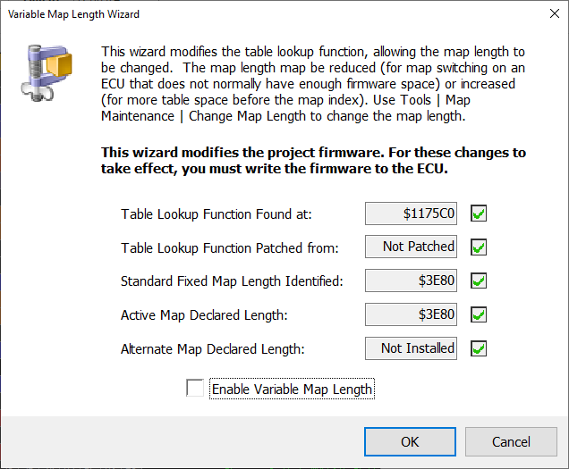
· Enabling variable-length maps.
Standard MEMS3 maps for a given firmware are always the same
overall length. This length is determined by the address of the table index at
the end of the map, which is normally fixed. The ECU refers to a specific table
by its fixed address in the table index. This means that any space recovered by
reducing the space used by tables etc. does not normally reduce the size of the
map. Instead it just results in more unused space
between the end of the last table and the index.
It is possible to install a patch into the table lookup function
to allow the map length to be changed. This patch calculates the difference
between the map length declared at the start of the map (normally at address
$13C000) and the standard map length for the firmware (which is captured from
the map length at $13C000 during patch installation and hard-coded into the
patch itself). It then offsets the table addresses passed by the ECU code by
this difference, effectively redirecting them to the new table index location.
The patch only requires 3 words of code. I have managed to find
small optimisations in each of the three table lookup functions used (Rover K
Series long term fuel trim, Rover K Series NASP / Land Rover Td5 and Rover K
Series Turbo) amounting to 3 words each, meaning that the patched functions are
all exactly the same length as the originals and can be overwritten in situ
without allocating additional ROM space for copies.
o
In the case of the Rover K Series long term fuel
trim lookup function, I was able to relocate a block of code from the end of
the function to a position earlier in the function. This brought two branches
which jumped to that code into the range where 1-word BRA.S branch
instructions could be used in place of the original 2-word BRA.W
instructions, saving 2 words.
o
In the case of the Rover K Series NASP / Land Rover
Td5 lookup function, I was able to relocate a block as above, but this block
was only branched to in 1 place so only 1 word was saved. Elsewhere in the
function there was a 2-word MULS.W multiplication being used to multiply
a value by 2, which is equivalent to a shift of 1 bit left, so I replaced this
with a 1-word ASL.W #1 instruction saving 1 more word.
o
In the case of the Rover K Series Turbo lookup
function, I was able to replace a 3-word BRA.L long branch to the RTS at
the end of the function with a 1-word inline RTS instruction, saving 2
words.
o
In all three cases, I was able to replace a 2-word MOVE.B #$FF,D0 instruction at the end of the function with a 1-word MOVEQ
#-1,D0 instruction, saving 1 more word. This is not exactly equivalent, but
the difference does not matter in this case. The function returns $FF in the
lower byte of D0 to indicate that an error occurred. The contents of the higher
bytes of D0 are not defined. The original instruction sets the lower byte to
$FF, the replacement instruction sets the lower word $FFFF, meaning that the
lower byte is still set to $FF as before. The fact that it also sets the second
lowest byte of D0 to $FF is irrelevant. In fact, in all firmwares that I’ve
looked at, the error code returned is not even checked in the lower byte.
To patch the lookup functions to enable variable length maps,
select Tools | Wizards | Variable Length Map from the menu, tick the Enable
Variable Map Length box and the built-in wizard will make all of the
necessary changes.
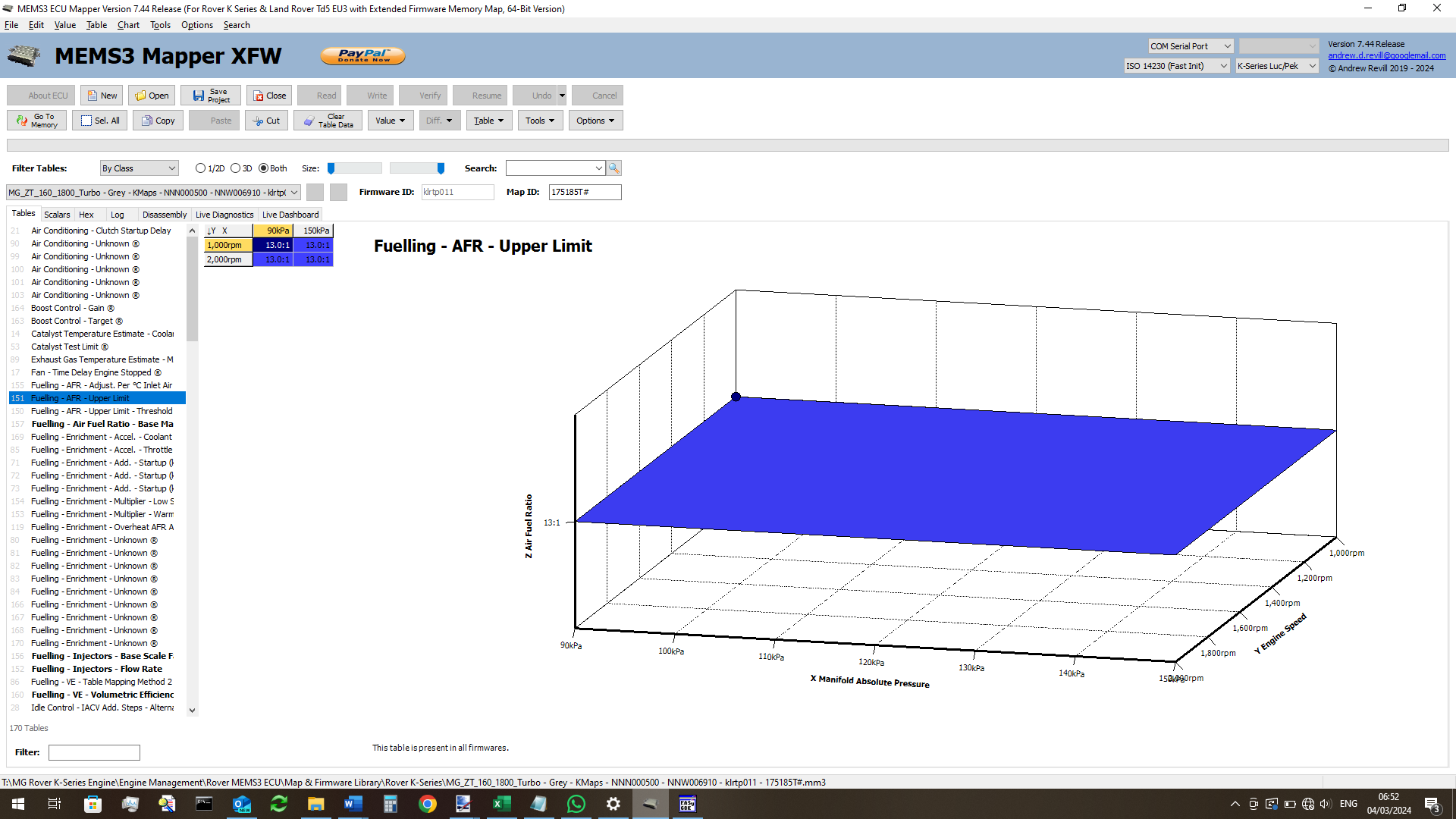
· Collapsing all flat tables to single cells.
Some tables in the map only have a single Z value, used for all
X and Y values. Some of these tables (typically those for unused features
“mapped out” at the factory) are reduced to nominal 2x2 or 1x1 format as shown
below. Others (typically those “flattened” by tuners) are still in the form of
larger tables with sensible X and Y axis data, but a single flat Z value. All
of these can be reduced to a single cell, saving considerable memory space. A
table with a single cell will always return the same single Z value, whatever X
and Y values are passed into it.
There’s was bit of a twist involved in implementing this one. It
turns out that the NASP version of the lookup function requires single-cell
tables to be declared at 1x1, but the turbo version of the same function
requires them to be declared as 0x0 and will not work correctly with a table
declared as 1x1. This is despite the fact tat it expects a table with only one
value on one of the axes only to be declared as e.g. 3x1 rather than 3x0. The
routines in MEMS Mapper therefore only let you collapse tables in projects
which have firmware in them, and where it can find and identify the version of
the table lookup function used. They then collapse the tables using the format
appropriate to the function used by the firmware.
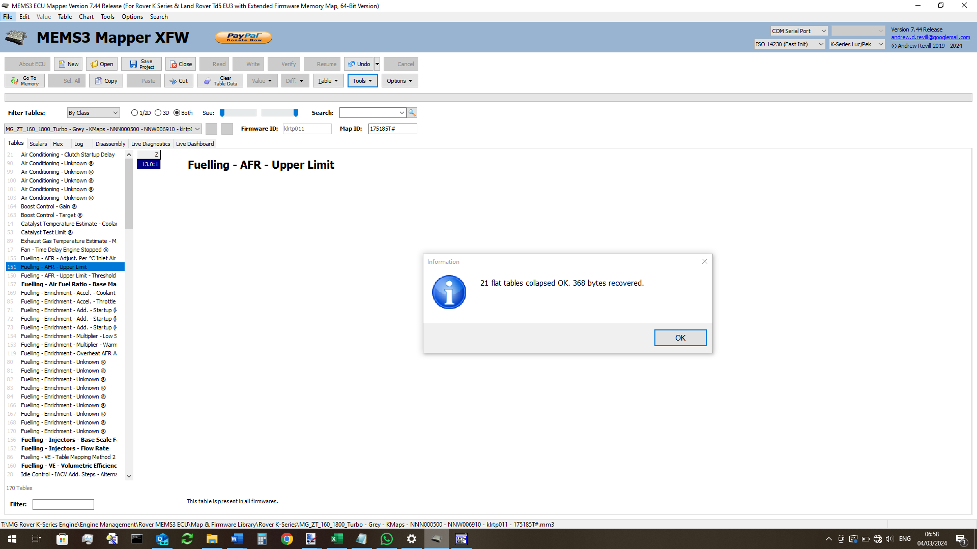
To collapse all flat tables in the map in one go, select Tools
| Map Maintenance | Collapse All Flat Tables from the menu.
You will then see a summary of the space recovered. You will
also see that the previously expanded flat tables are now collapsed to single
cells.
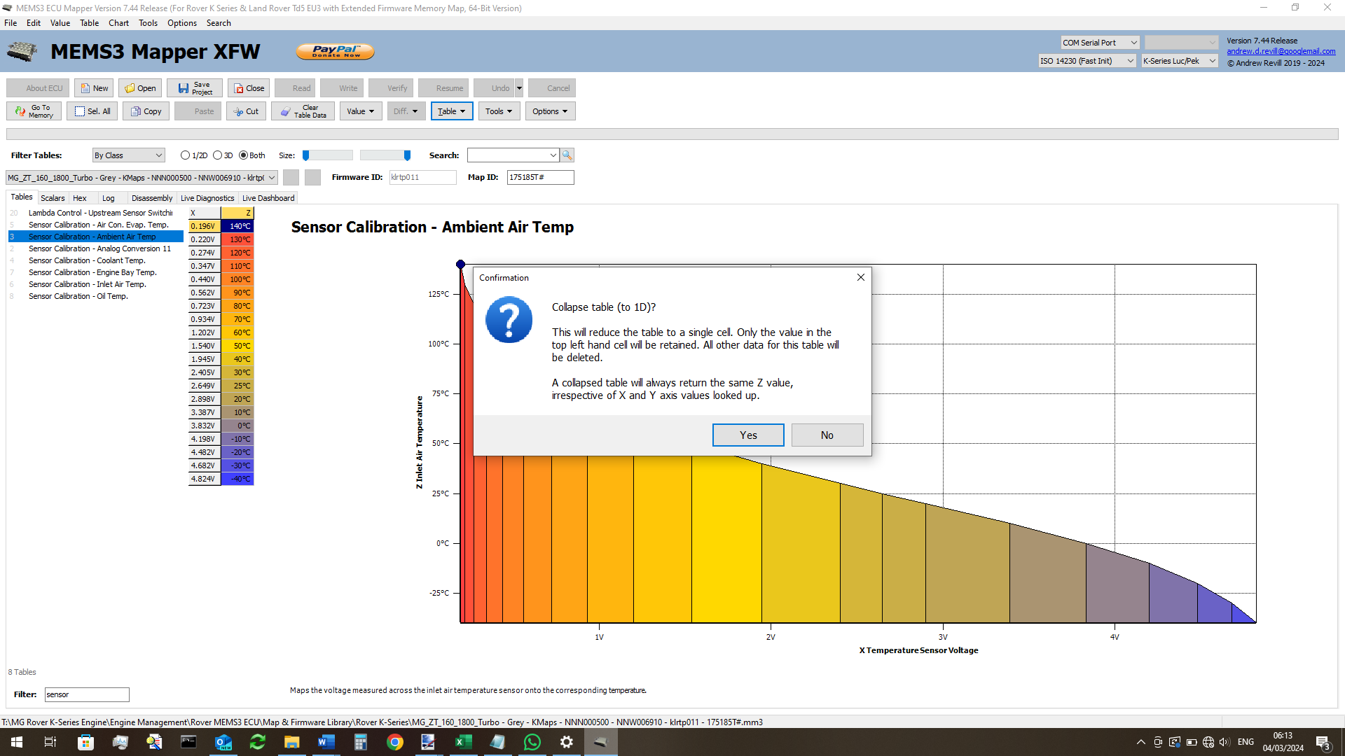
· Collapsing the Sensor Calibration - Ambient Air Temp. table.
The MG ZT ECU gets its ambient air temperature data over CANbus
from the instrument cluster. It does not have a sensor wired directly to the
ECU, does not use the analog input and does not use the corresponding
calibration table in the map. This table is however generally still present and
fully mapped as it is in all K Series maps. It is possible to collapse this
sensor calibration down to a single cell as it is unused.
To do this, highlight the table in MEMS Mapper and select Table
| Collapse Table (to 1D) from the menu.
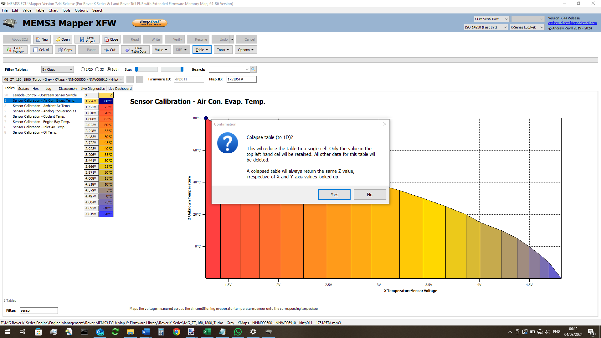
· Collapsing the Sensor Calibration - Air Con. Evap. Temp. table.
The MG ZT ECU gets its air conditioning evaporator temperature
data over CANbus from the instrument cluster. It does not have a sensor wired
directly to the ECU, does not use the analog input and does not use the
corresponding calibration table in the map. This table is however generally
still present and fully mapped as it is in all K Series maps. It is possible to
collapse this sensor calibration down to a single cell as it is unused.
To do this, highlight the table in MEMS Mapper and select Table
| Collapse Table (to 1D) from the menu.
• Collapsing the
Unused Duplicate Air Conditioning Table.
The MG ZT ECU appears to contain two duplicate copies of a table
associated with the air conditioning system, possibly inherited from two
different optional modules. Only one copy of this table is referenced by the
firmware, the other one is redundant and just taking up space. It is possible
to collapse this sensor calibration down to a single cell as it is unused.
To do this, highlight the table in MEMS Mapper and select Table
| Collapse Table (to 1D) from the menu.
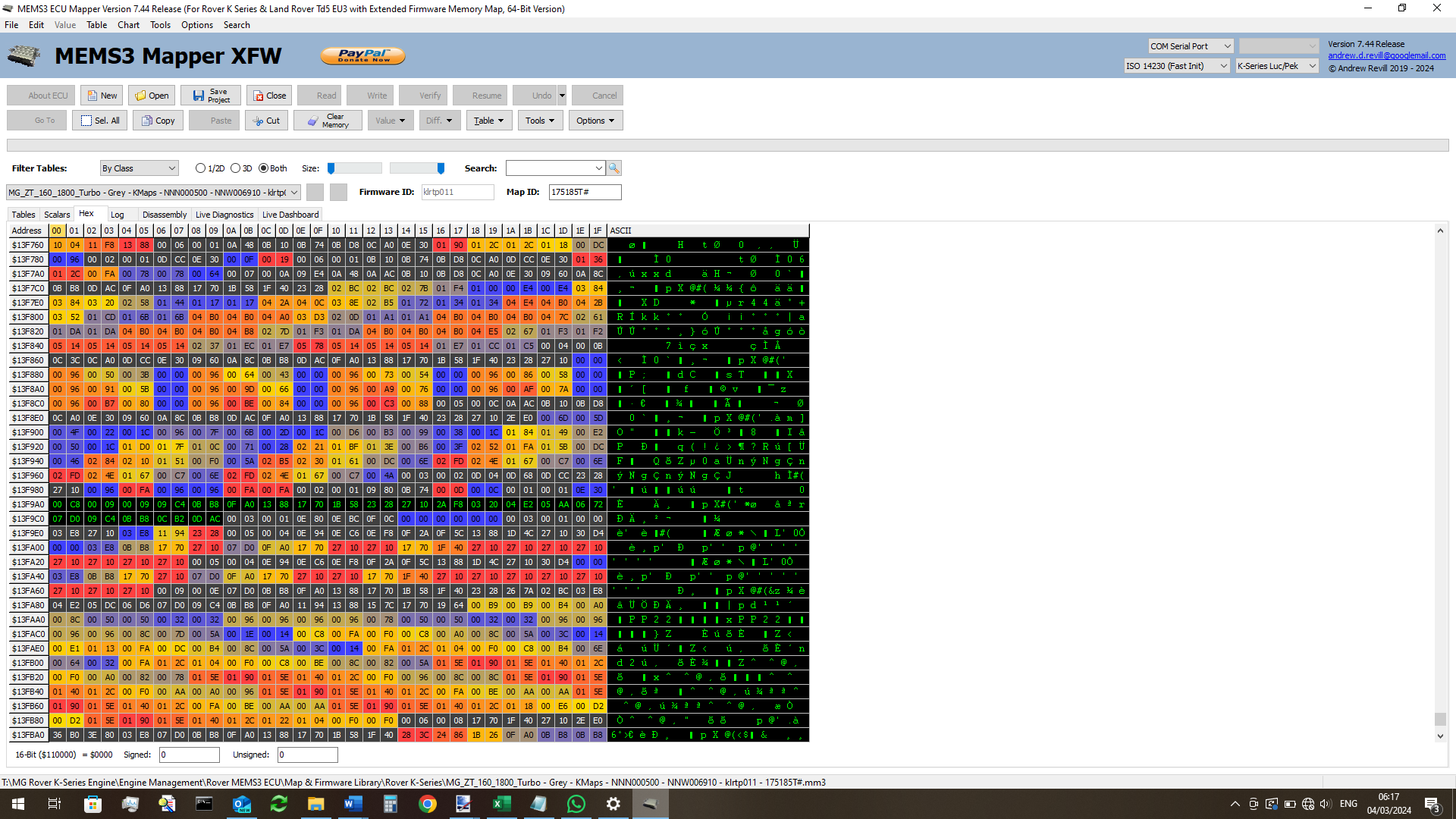
· Compacting the map table space.
Many K Series maps have small runs of wasted space between some
of the tables in the map. It looks as though the tools used by Rover did not
always recover the space released when table sizes were changes. These can vary
in size from 4 bytes to over 40 bytes and cumulatively, they can add up to
quite a bit of wasted memory. You can see an example here, where the bytes
starting at $13F9A0 are unused.
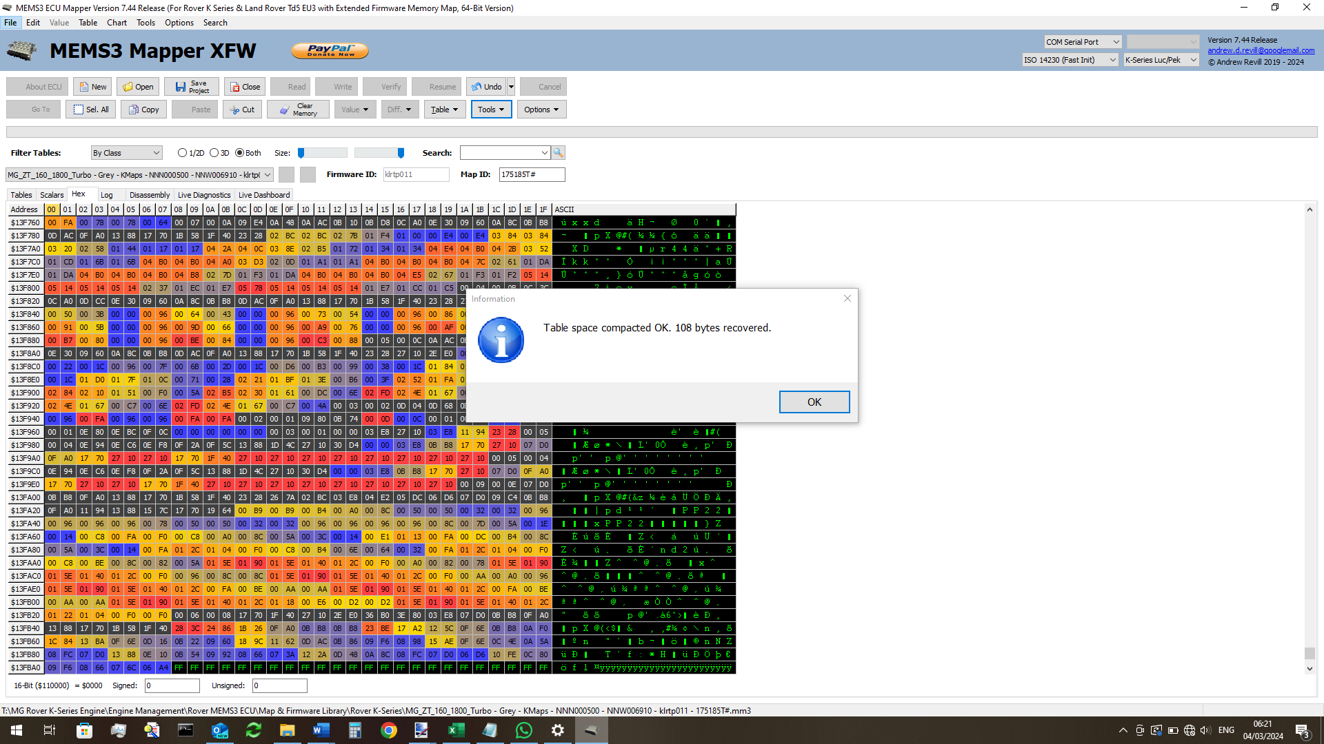
It is possible to recover all of these wasted bytes by
compacting the subsequent tables downwards in memory, adjusting the pointers to
them table index at the end of the map accordingly.
To do this, select Tools | Map Maintenance | Compact Table
Space from the menu.
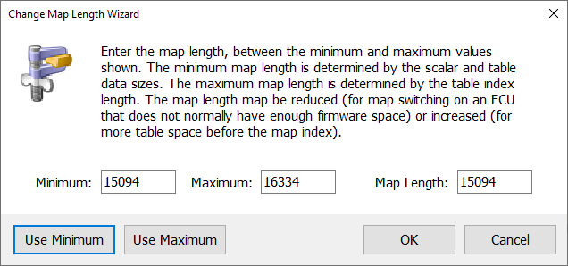
· Changing the map length to the minimum possible value.
The above changes will have recovered space in the table area of
the map, but as described previously, the overall size of the map is determined
by the location of the table index. So far, any recovered bytes will just be
extra space between the end of the last table and the table index, and will not
reduce the overall map length. With variable map lengths enabled as described
above, it is now possible to relocate the table index to place it almost
immediately after the last table in memory. This properly reclaims the space
and shortens the map.
To do this, select Tools |Map Maintenance |Change Map Length
from the menu. Then click the Use Minimum button to select the shortest
map length consistent with the available space and data (the minimum map length
places the table index almost immediately after end of the last table, the
maximum map length places the table index almost to the top of the map space,
allowing for some byte which are reserved for checksums and for use by MEMS3
Mapper or custom patches).
· Installing the map switching patch.
With all of the above in place, in the example I was working on here
the map switching patches can be installed. The Coolant map switch is more
complex than the others and requires considerably more space for the program
code than any other map switch. It is unlikely to be installable on an ECU that
is this severely limited in terms of available firmware space. It is however a
“last resort” options and nearly all Rover K Series ECUs at least will have
available inputs to allow for the use of other, simpler, better options. All of
the other map switches use the same standard allocation for map switching code
and should all fit.
Select Tools | Project Tools | Install Map Switch Patch
then any EXCEPT Coolant from the menu.
In
one example of a tuned MG ZT Turbo ECU, this resulted in a total of just 32
bytes spare (out of a total ROM space of 262.144 bytes)! This is obviously
very marginal and some other MG ZT Turbo maps may still not fit. If you try
this and find that you are still unable to install the desired map switch
patch, your only option will be to reduce the size of one or more tables by
deleting axis values. In most cases, only a small amount of additional space
will need to be recovered as most of the maps are very similar in size. And in
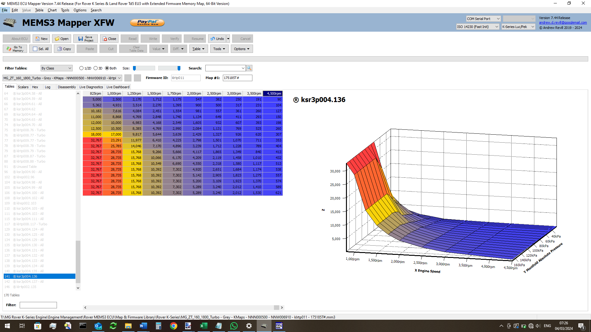
most cases it possible to identify the odd axis value
in one or two tables which hardly impacts on the shape of the table (i.e. where
Z values around that axis point would be interpolated and would return very
similar values to those specified for the axis point). As an example of what
could be done, it is extremely unlikely that removing the 4000rpm column from
the following table would have any significant impact on the shape of the
table.
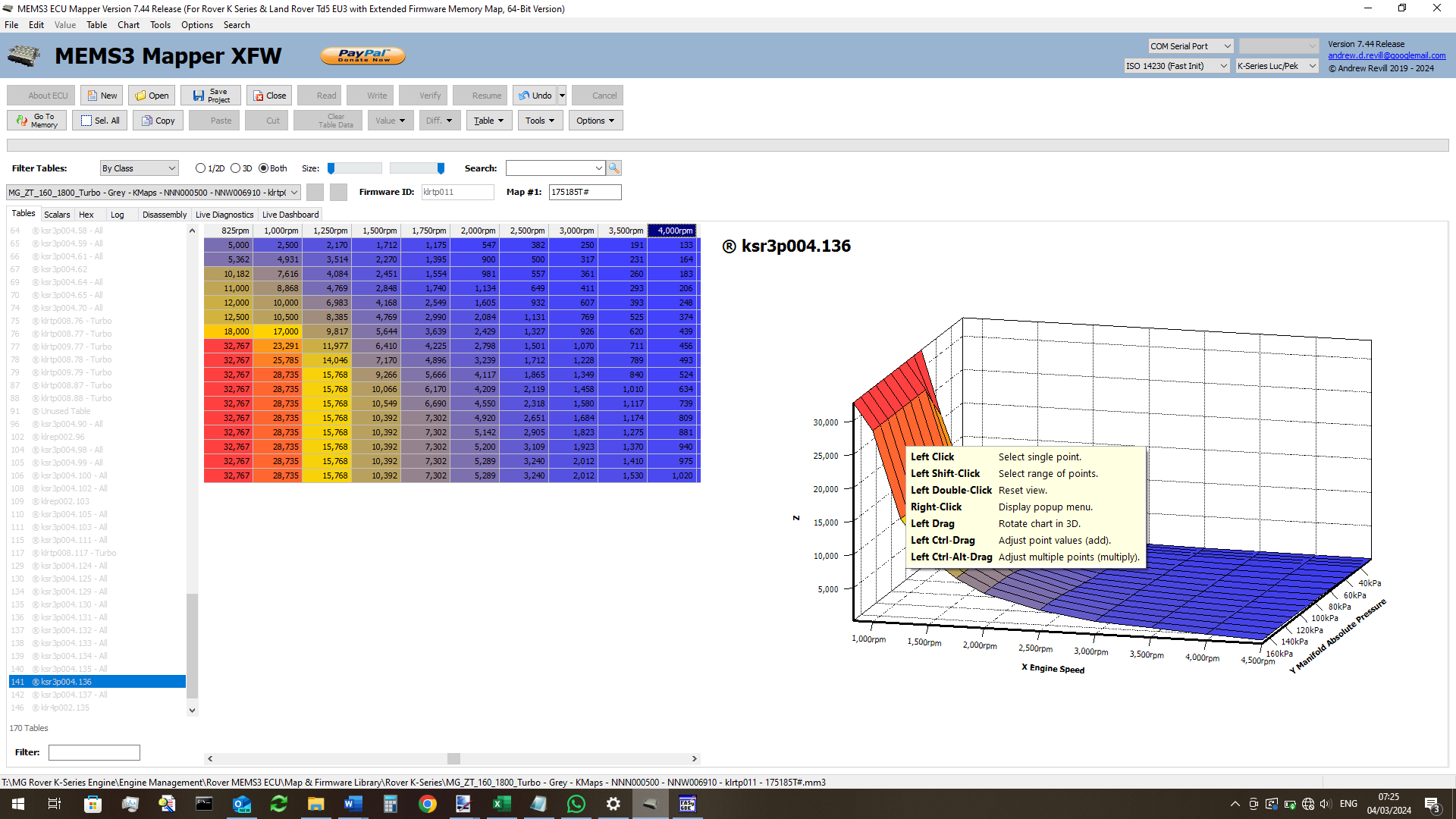
Deleting this column would release 36 bytes of memory (remember that you would
need) to reduce the map length again as the recovered space will initially be
below the table index).