MEMS3 MAP Sensor Scaling
Download
Link: https://andrewrevill.co.uk/Downloads/MEMSTools.zip
Using my MEMS Mapper you can now
easily adjust the map to work with a different MAP sensor.
This is something that quite a few people
have asked me for. There are two main uses:
·
When installing a
larger turbocharger, the boost available may exceed the range of the stock MAP
sensor. But it you fit a higher boost range MAP sensor, it will read incorrectly.
·
When adapting an EU2 (e.g. MEMS2J VVC) to use a MEMS3 ECU. This can be
done by rewiring around the ECU plug alone, allowing you to use the original
engine wiring loom and sensors. But the EU2 MHK100600 MAP sensor does not use
the same calibration as the EU3 MHK100820 MAP sensor, so the ECU sees the wrong
MAP (the EU3 sensor is not
straight swap for the EU2 sensor on the plenum either).
By following the instruction below, you
will be able to tell the MEMS3 ECU about the new MAP sensor calibration so that
it will then read the MAP correctly.
Basic Instructions
You will need to download the latest
version (5.39 or later) of my MEMS Tools from here: https://andrewrevill.co.uk/Downloads/MEMSTools.zip
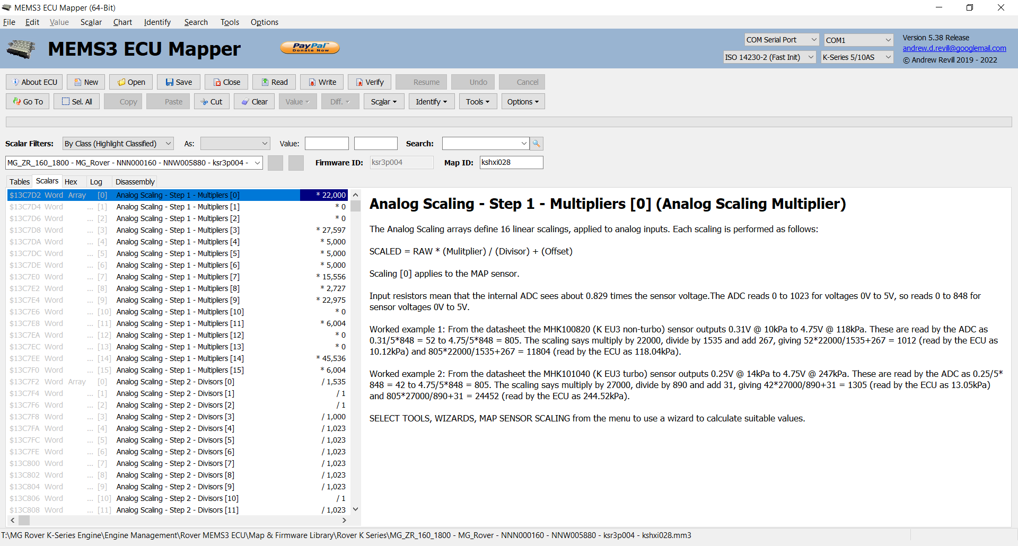
If you open a file in this version you
should see a lot of new scalars listed, with descriptions “Analog Scaling ...”
as shown below.
If you are using a firmware version that
I haven’t seen, these will not be found. In that case just click Identify,
Keep Existing and it should find them all automatically.
Working out and configuring the scaling
numbers correctly is a little bit complicated, so I’ve added a wizard to do it
for you.
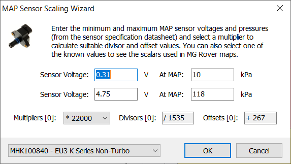
Click Tools, Wizards, MAP Sensor
Scaling and you should see a dialog like this:
If this
menu item is disabled, the application has not been able to identify the relevant
scalars in the map. Ensure that you have used the Identify, Keep Existing system to identify the scalars.
In this dialog you enter the pressure and
output voltage range for the sensor you are using, and it will calculate the
scaling numbers. You can also just select one of the standard sensors from the
combo box to populate the dialog with the numbers that MG Rover used in their
maps for that sensor. So far I’ve only found the formal specifications for the
EU3 sensors, but I’ve worked out substitute specifications for the EU2 sensor
by working backwards from figures in stock EU2 MG Rover maps. If you’re using a
sensor which isn’t on the list, you can enter the numbers manually. If you
don’t have the numbers, worst case you can make a guess and then look at the
MAP numbers reported by the ECU and adjust until it looks about right.
If you are using a different sensor and
you have some numbers, please let me know and I’ll add it to the list.
There are three numbers that control the
scaling, a multiplier, a divisor and an offset. You can choose any multiplier
you like between 20000 and 32000 and the tool will calculate the divisor and
offset that go with it. As far as I can see it makes very little different what
number you choose as the multiplier.
When you’re done, click OK to
update the current map. If the OK button is disabled it means that the
angles entered are invalid, for example duplicated or out of order.
This wizard is compatible with live
mapping mode and will let you play with the sensor scaling on a running engine.
Technical Details
The MAP sensor produces an output voltage
in the range 0-5 Volts. Inside the ECU, two resistors divide this voltage by a
factor of 1.2. The ADC uses a 5V reference and converts voltages in the range
0-5 Volts into digitised values in the range 0-1023. Because of the resistive
divider, sensor voltages 0-5 Volts are seen by the ADC as approximately 0-4.17V
and are therefore converted to digitised values in the range of roughly 0-848.
The output of the ADC is the multiplied
by the Multiplier number, divided by the Divisor number (using Integer maths)
and the Offset number is added. So take a worked example for a stock non-turbo
EU3 K Series with an MHK101820 sensor: An MAP of 75kPa will produce a sensor
output of 2.982V. The ADC sees 2.982/1.2=2.485V and converts this into
digitised code 508. This is multiplied by 22,000 to give 11,176,000, divided by
1535 to give 7280 and then 267 is added to give 7547.
The ECU reads this as 75.47kPa, which is approximately correct (When I work out
my own scaling from the specs for the standard sensors, I come up with slightly
different numbers for the scaling factors to those used by MG Rover, hence the
slight discrepancy above. I get a divisor of 1541 instead of 1535 and an offset
of 246 instead of 267. Using these numbers in the above example gives a result
of 74.98kPa. I can only guess that Rover calibrated the sensors themselves and
found that they weren’t quite to the stated specs, so used the numbers they
measured instead. They are very close anyway. If you select one of the standard
sensors from the list, the wizard applies Rover’s values from stock maps rather
than the ones calculated from the specs to be safe).
You will see there are 16 multipliers, 16
divisors and 16 offsets in the map. These are all used for different sensors
and scalings. I haven’t yet investigated what the others are for but the first
number in each set, listed as Multipliers [0], Divisors [0] and Offsets [0] are
for the MAP sensor. You can edit these numbers directly; the wizard just works
them out and plugs them in for you.