MEMS3 Live Mapping – Remapping with
Engine Running
Download
Link: https://andrewrevill.co.uk/Downloads/MEMSTools.zip
Using my MEMS Mapper application it
is now possible to edit map values live, with the engine running on a rolling road.
The edited values take effect immediately.
This represents the ultimate destination I was aiming for with my MEMS3 mapping application. It allows you to remap the ECU with the engine running. You can for example adjust ignition timing and fuelling with the car running live on a rolling road and see the effects immediately. There is no need to shut the engine down and reload the map during a mapping session.
Motivation
A special “Thank You” goes out to Troy and Alex and Northampton Motorsport. While helping them to remap a Caterham last year, Alex made the throwaway comment “It doesn’t do live mapping does it?” and Troy replied “No, the ECU’s not got anywhere near enough RAM for that.” … which sounded like a challenge to me! I actually finished this quite a while ago, but I’ve been too tied up with engine builds to take the time to write it up and publish it. The engine building front has gone a little quieter for a bit now, so here goes …
Highlights
The main highlight features:
· This seems to work well on almost any petrol MEMS3 ECU and any firmware version, and appears compatible with every MEMS3 I’ve ever seen in a Caterham. Technical Details: I’ve tested it on a selection of ECU hardwares and with a wide range of different firmware versions, both VVC and non-VVC, automatic and manual, turbo and normally aspirated. The only petrol ECUs that I have found issues with are the klrep002 firmware (for the Rover 75 1400, used on the very early NN100682 ECU, which was riddled with bugs anyway and seems to include a lot of development code, leaving only 984 bytes of RAM available) and the kwr3p011 firmware (used on 1.8 automatics – this may be a general issue with automatics as the firmwares are a lot larger due to the StepSpeed control software, which leaves insufficient free firmware space to install the patch). The code as it stands has NOT been tested with TD5 diesel ECUs. I very much doubt that it could be adapted for use with these as they have very little free RAM (they dedicate half of their RAM for TPU microcode emulation).
· It’s all done through my FREE MEMS Mapper application in a couple of clicks. You can use all of the features of the mapping application to edit either the main or alternate map and to switch between the two.
Demo Video Link
I’ve recorded a short YouTube video here which shows the live mapping system being used on my own car, a Caterham 7 VVC 160. It shows the whole process end to end by way of example.
Step by Step Example
I’ve tried to write this article with the key information and examples that you need to learn to use the feature at the start and technical details afterwards. You can skip those if you don’t need to know how it works inside, although if you do decide to set this up on your own ECU I would recommend reading to the end before you start.
Below is a walk-through of a step by step, worked example. This is the example taken from the demo video above. For the purposes of this demonstration, I was sitting in my own car, a Caterham VVC 160, with the laptop plugged into the OBDII port. All of the demonstration was done live on my own car, with the engine running where appropriate. The screenshots below are all taken from frames captured from the above video.
You will need to download Version 5.21 or later of MEMS3 Tools from here: MEMSMapper.htm.
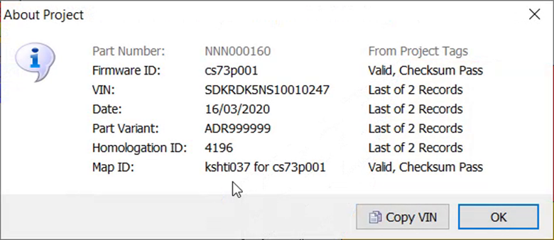
We start by reading the ECU as usual (or opening a file we read and saved previously). If you’re not sure about how to do this, refer to MEMSMapper.htm. In the demonstration, I read the existing contents of the ECU.
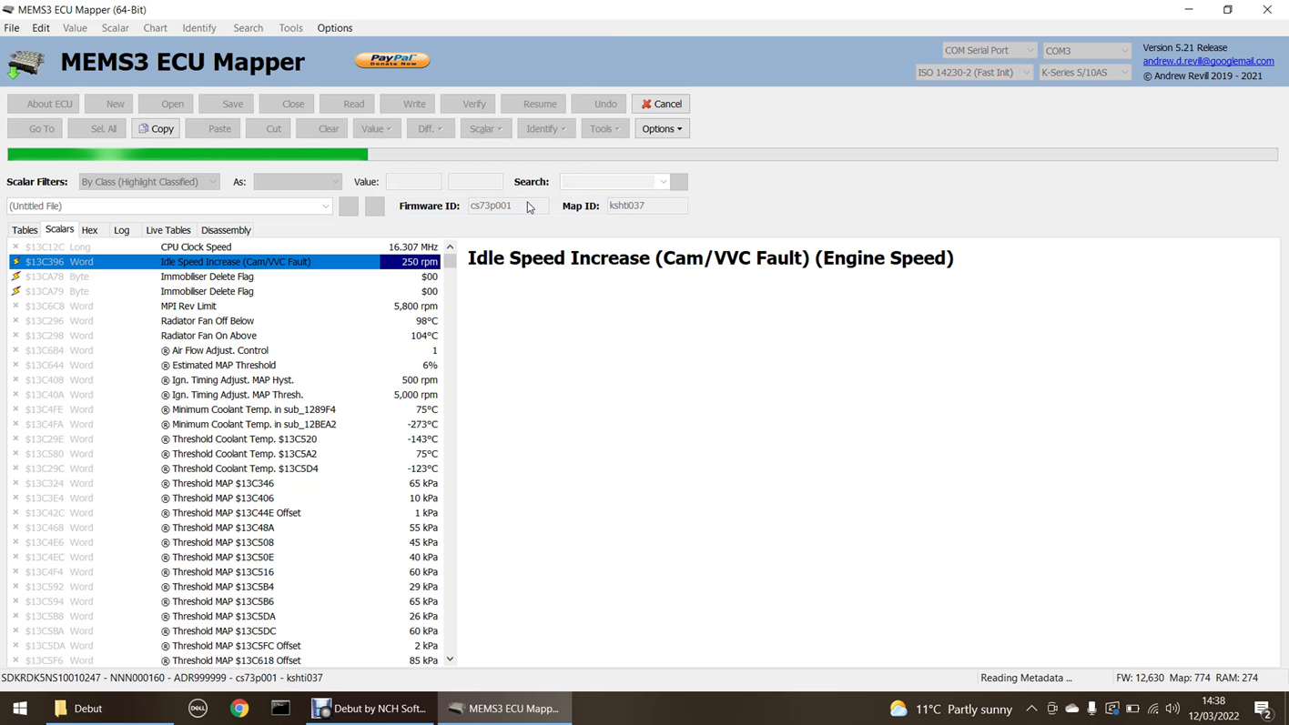
We will need to read both firmware and map. When complete it will show the firmware version (“cs73p001” in this case) and the map ID (“kshti037” in this case):
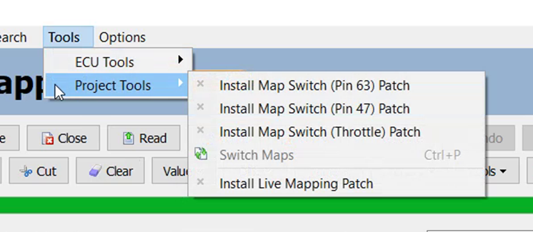
Next we will need to install the live mapping patch into the project. Check Install Live Mapping Patch under the Tools, Project Tools menu:
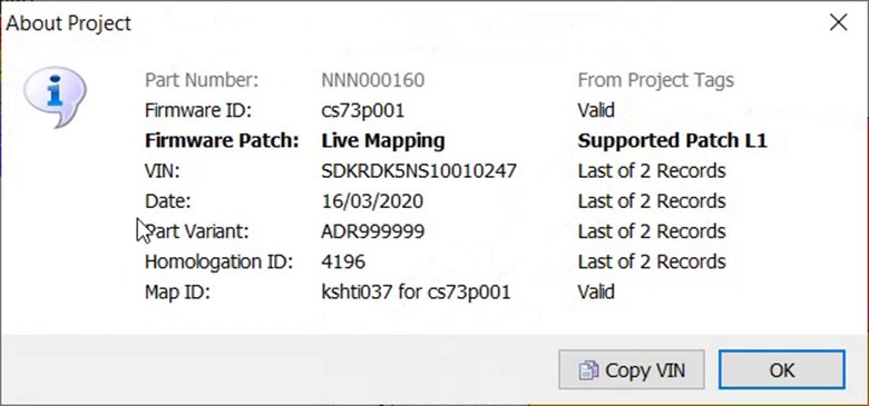
A dialog box like the one below will be displayed, now confirming that the live mapping patch is installed.
All of the changes made so far are made to the project in MEMS Mapper only. We have not made any changes to the ECU itself yet. Nothing is changed on the ECU until we write the project back to the ECU.
Once the live mapping patch is installed, you will see some new features in the user interface:
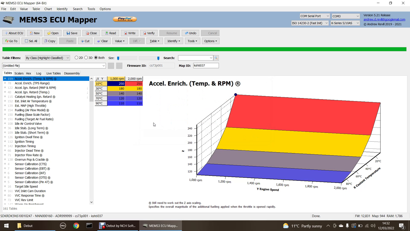
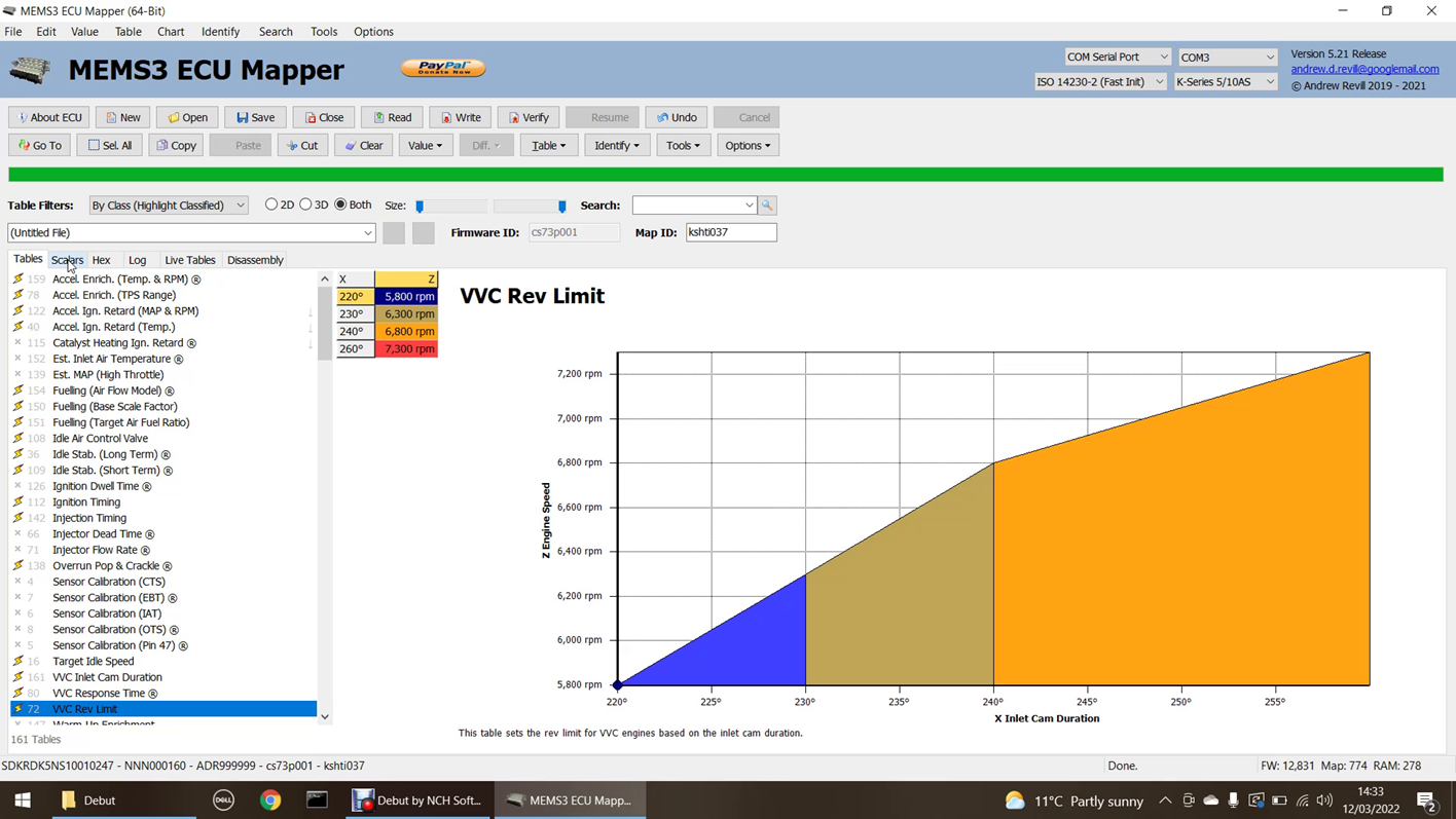
Down the left hand side of the list of tables on the Tables tab you will now a column of
symbols, showing as ![]() ,
indicating that the tables are not currently selected for live mapping. You can
click on these to select a table for live mapping. The symbol will then show as
a “Live” indicator
,
indicating that the tables are not currently selected for live mapping. You can
click on these to select a table for live mapping. The symbol will then show as
a “Live” indicator ![]() .
The same symbols are displayed down the left hand side of the list of scalars
on the Scalars tab, and these allow you to select which scalars you want to
make available for live mapping:
.
The same symbols are displayed down the left hand side of the list of scalars
on the Scalars tab, and these allow you to select which scalars you want to
make available for live mapping:
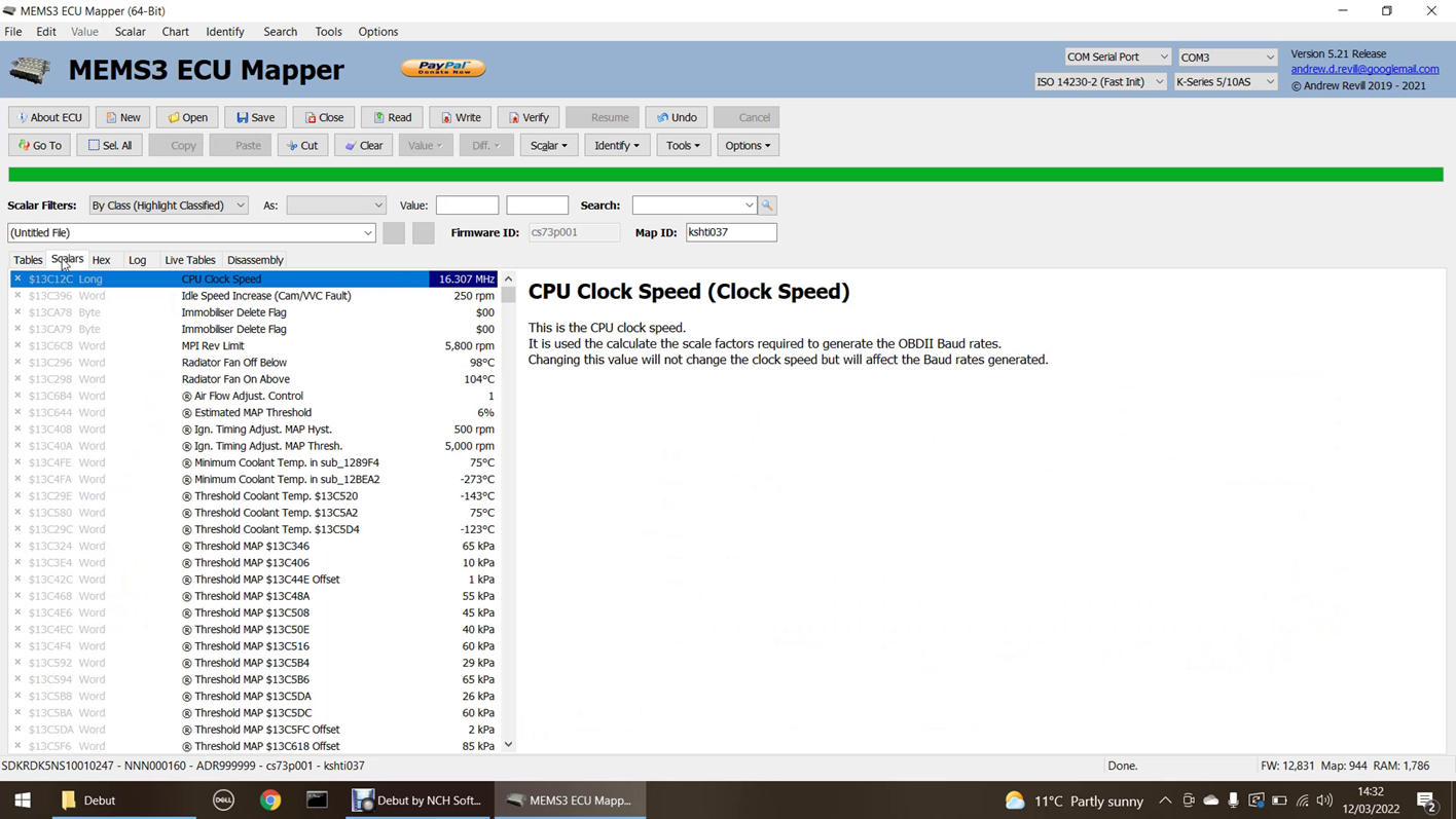
In the bottom right hand corner of the status bar, you will see numbers indicating the numbers of bytes of available free firmware space, map space and RAM:

These are updated as you select tables and scalars for live mapping. See the section on Data Size Limitations below for more information. For the purposes of the demonstration, I selected the following 17 tables and 3 scalars, which include the large fuelling and ignition timing tables:
You can see that I still had a lot of spare firmware and map space, and a useful amount of RAM still remaining. The exact amount of available free firmware, map and RAM space will vary quite a lot between different ECUs and different firmware versions, but in the vast majority of cases there will be plenty available to allow all of the tables and scalars that you would need to be available for live mapping to be selected simultaneously.
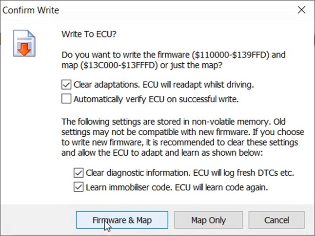
Once we have selected which tables and scalars we want to be
available for live mapping, we need to write the modified firmware and map back
to the ECU. So far all of the changes we have made have been in the MEMS3
Mapper project only and no changes have been made to the ECU yet. We need to
write back both the firmware and the map at this stage. See the section on What Do I Need to Write Back? below for more information.
Once the write has finished, the ECU is now prepared for live mapping. At this point we can start the engine. The car should run and drive normally. The modifications to the firmware will copy the original values for the live tables and scalars from ROM into RAM as the ECU boots up, and the RAM copies will then be used. As they are initialised with their original values, the engine should run exactly as it normally would.
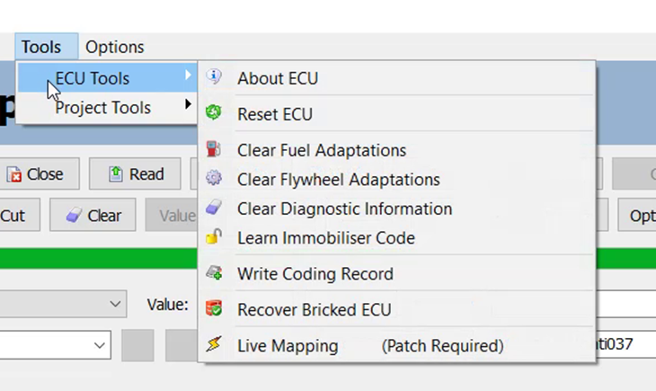
We now need to start a live mapping session with the ECU. Once the ECU has been prepared as above, you can run any number of live mapping sessions. To start a live mapping session, click Live Mapping under the Tools, ECU Tools menu:
The application will spend a few seconds going through a number of processes as it starts the live mapping session. You will see the progress bar moving across the top of the screen and a number of status messages displayed in the status bar at the bottom of the screen:
During this time, a number of checks are performed to ensure that everything is consistent and that live mapping can proceed safely. The ECU is checked to make sure that it has the appropriate live mapping patch installed, the definitions of which tables and scalars are selected for live mapping are downloaded from the ECU into the project (the ECU and project must agree on what is live, and the definitions in the ECU take precedence) and the value of the live tables and scalars from the project are uploaded to the ECU (this ensures that the live mapping session starts from the current definition of the map in the project – see the sections on What Happens if I Write Invalid Values to the ECU? and What Happens if I Lose Connection? below for more information). Once everything has been checked and initialised, the live mapping session begins:
Once in live mapping mode, the progress bar shows a marquee pattern to indicate that there is an ongoing operation.
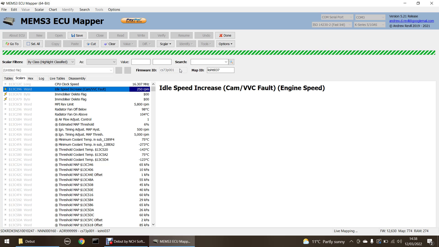
If you now click into the Live Tables tab as shown below, you will see a display indicating which tables the ECU is using in real time. This can be very useful to help identify the tables which are only used during idling, normal drive conditions, overrun etc. Each time a table is accessed, the corresponding cell changes towards a bright red colour, then fades over a short time period. This means that tables that are accessed continuously show in bright red, as seen with tables 1 to 8 below. Some tables are only accessed roughly once per second and these flash visibly, as seen with tables 49 to 51 below (this screen is much easier to appreciate in the demo video). In the top left hand corner of each cell is a small triangular tab. This changes colour much more slowly than the rest of the body of the cell. The purpose of this is to highlight tables which have recently come into use, or recently gone out of use as conditions change. A cell which is white (table not currently in use) but has a red or pink tab has only just stopped being used. A cell which is red (table is currently in use) but has a white or pink tab has only just started being used.
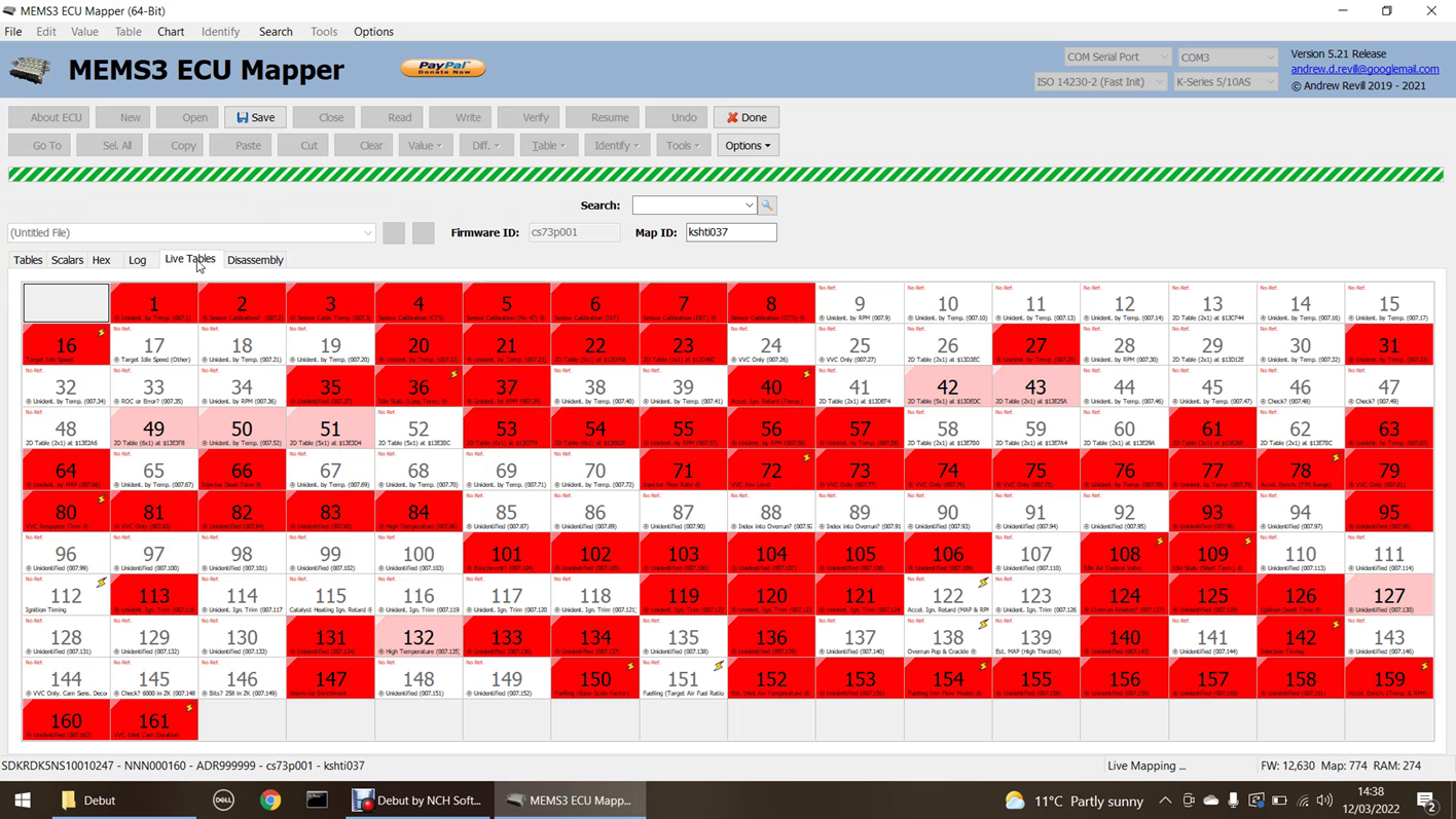
You can double-click any table cell to jump to that table in the Tables tab. Tables which are available for live mapping have small live indicator in the top right hand corner.
Cells which are shown in white with grey text have not been accessed even once since the start of the live mapping session. Some tables are only used under specific conditions, such as cranking, after start, overrun etc. This feature also helps to identify the main tables of interest which are actually used under normal driving conditions.
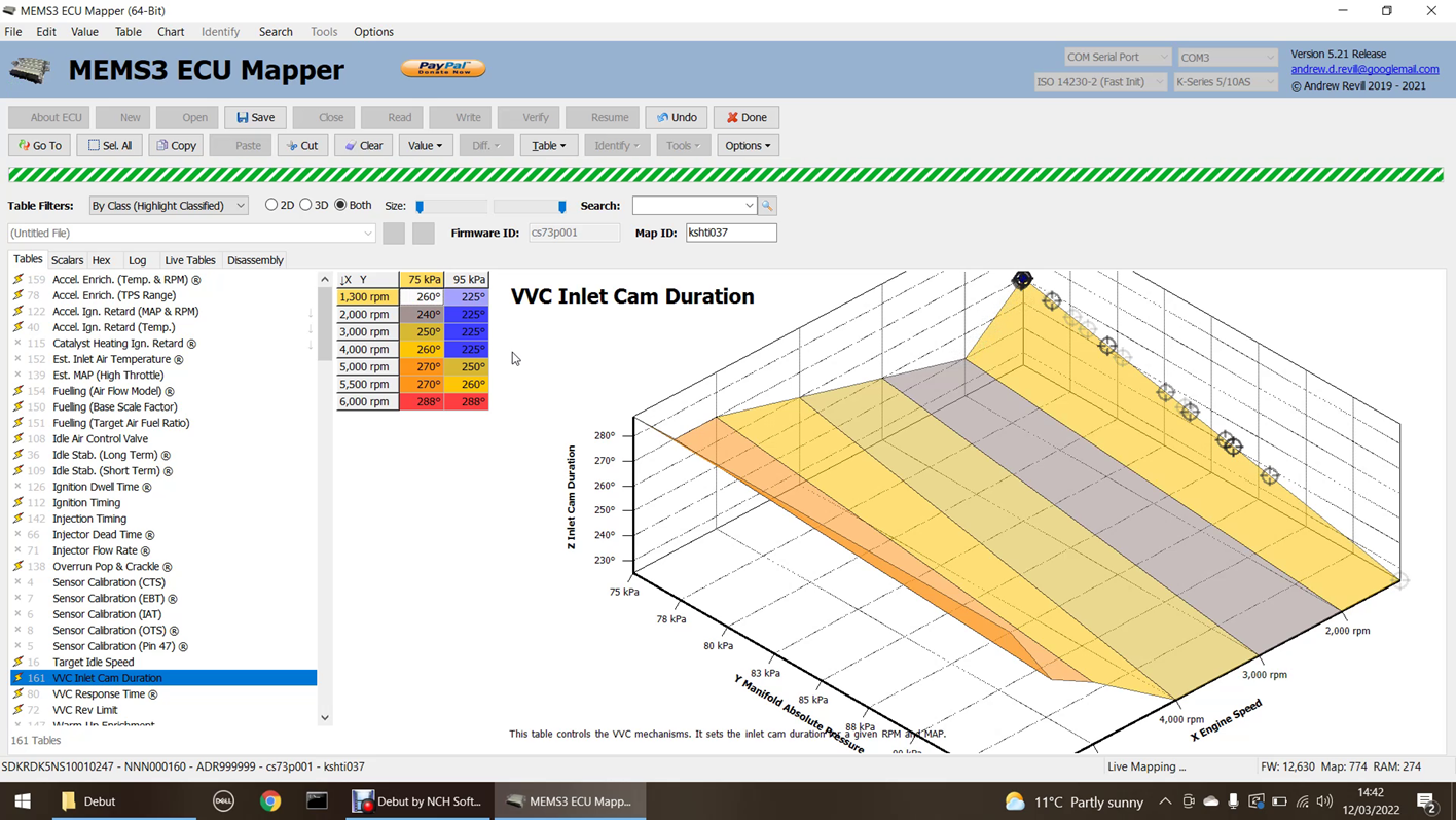
If you now click into the Tables tab, you will see that the ECU “hits” on each table displayed in real time, both on the table grid and on the 2D or 3D chart. On the table display, cells that are accessed are highlighted in white (in most cases the ECU will be interpolating between two cells on each axis, so will actually be using 2 or 4 cells, however for clarity just the nearest cell to the X and Y values looked up is highlighted); the white highlight fades over a short period of time leaving a fading trail which allows you to see the areas of the map that are in use at any given time, for example when detonation is noticed during a rolling road session. On the chart display, the cell hits are shown as dark grey crosshairs, centred on the X and Y values looked up by the ECU and the Z value returned by the lookup. These crosshairs also fade over time, leaving a visible trail. The crosshairs are correctly located in 3 dimensions, so can pass behind the surface of table data in the chart; this is therefore made partially transparent during live mapping, and this gives a really good feel for the movement of the active point in three dimensions and real time.
Note that the various live table displays are always available for ALL tables, not just those selected for live mapping, when a live mapping session is in progress. There is no need to select a table for live mapping just to be able to see how the ECU is using it.
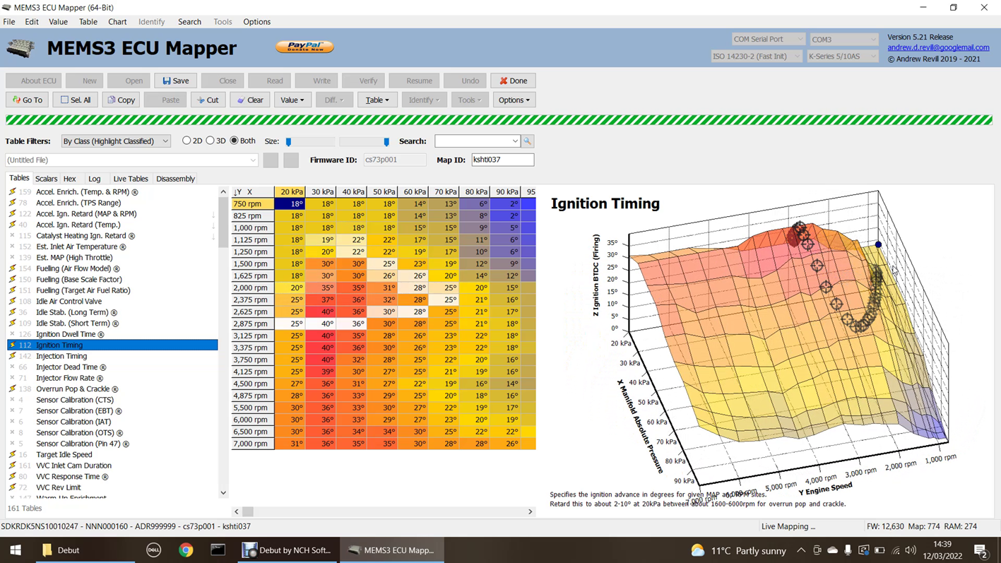
Here is the Tables tab with 2D table selected:
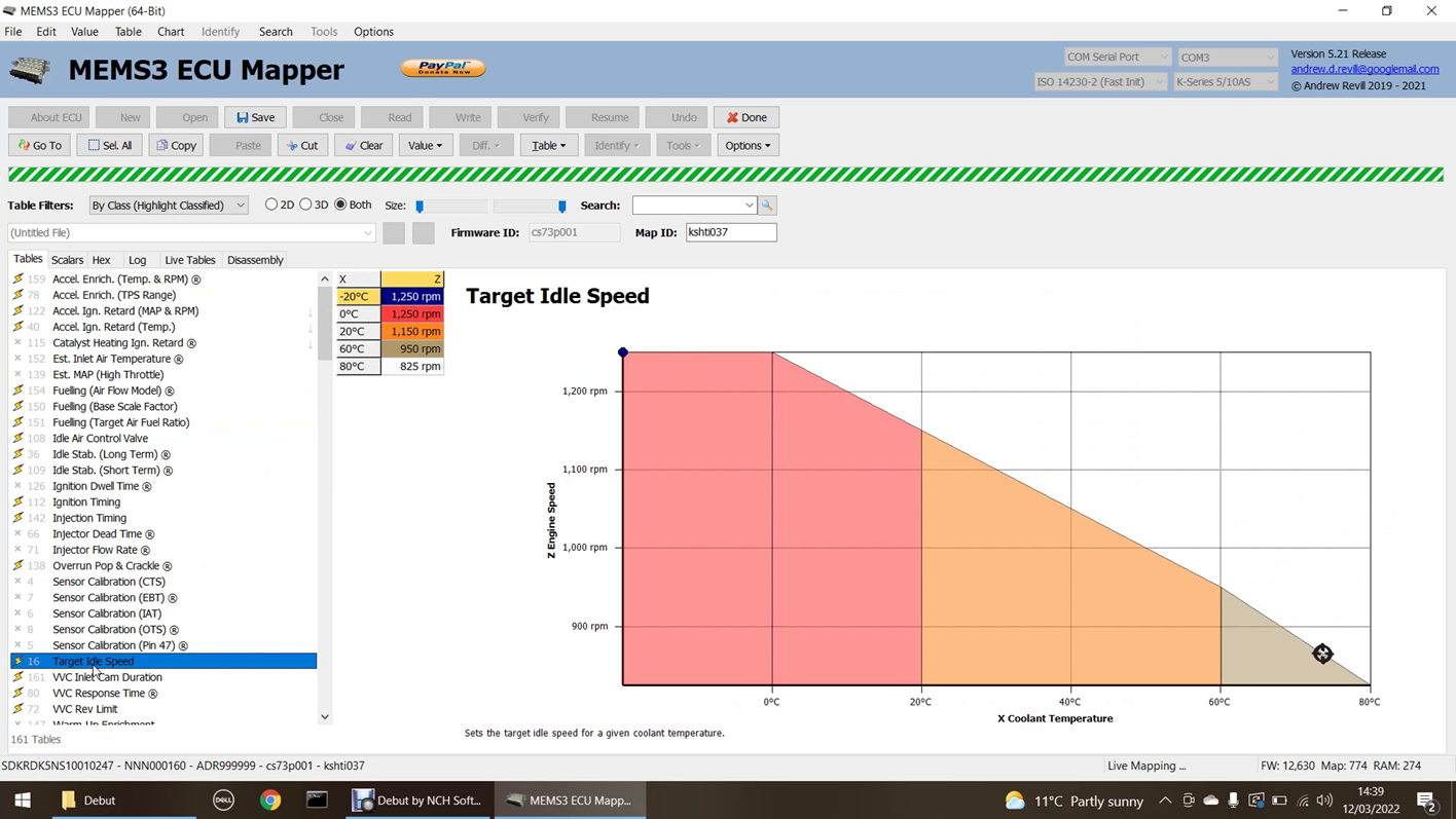
This table is the target idle speed, by coolant temperature. You can see that the coolant temperature here is just short of 80°C, and the resulting target idle speed is somewhere around 860rpm. In the video, you can actually see the coolant temperature increasing as the engine warms up. The crosshairs drift slowly to the right (higher temperature) and down (lower idle speed) in real time.
On important point to mention here: The Z values plotted on the charts are the values reported by the ECU. They are not calculated from the table values by MEMS Mapper. This allows you to see exactly what is happening inside the ECU’s table lookups. It means that if the crosshairs are following the line or surface on the chart, the ECU is using the same values internally as are displayed on the screen. If the crosshairs are not following the line or surface, the ECU is seeing different values for some reason. This should only happen in one of two cases:
· Very briefly after updating values in MEMS3 Mapper, before the values have been uploaded to the ECU. In order to allow values to be changed multiple times in quick succession, for example by holding down Ctrl-I to increase values sequentially, the upload to the ECU is actually deferred for a fraction of a second each time a value is changed. The values are only uploaded once the changes stop.
· Some tables have very low resolution. There are some tables (I’m not sure yet what they do) that have Z values in the range 0 to 5. Tables work in integer (whole number) raw values, so the ECU will never get a value of say 2.5 back from a lookup, it will always get 2 or 3. The corresponding chart is drawn as continuous line between the points, so you may see the value reported by the ECU deviating a little bit from the line on the chart, as the ECU will be rounding to the nearest integer.
During a live mapping session, we can change values in live tables and scalars (only those tables and scalars selected for live mapping) using all of the normal methods, We can type and edit values, we can copy and paste, copy down and across, interpolate down and across, increase or decrease highlighted ranges etc. All of these changes are uploaded to the ECU in real time. There is very small delay of a fraction of a second to ensure that all changes have been completed before the upload occurs.
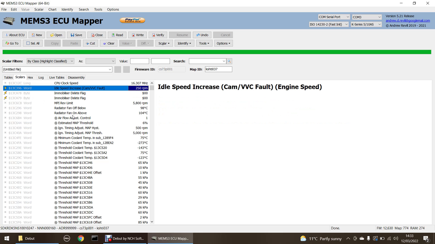
In the demo video, I edited the idle speed at 80°C to 1200rpm:
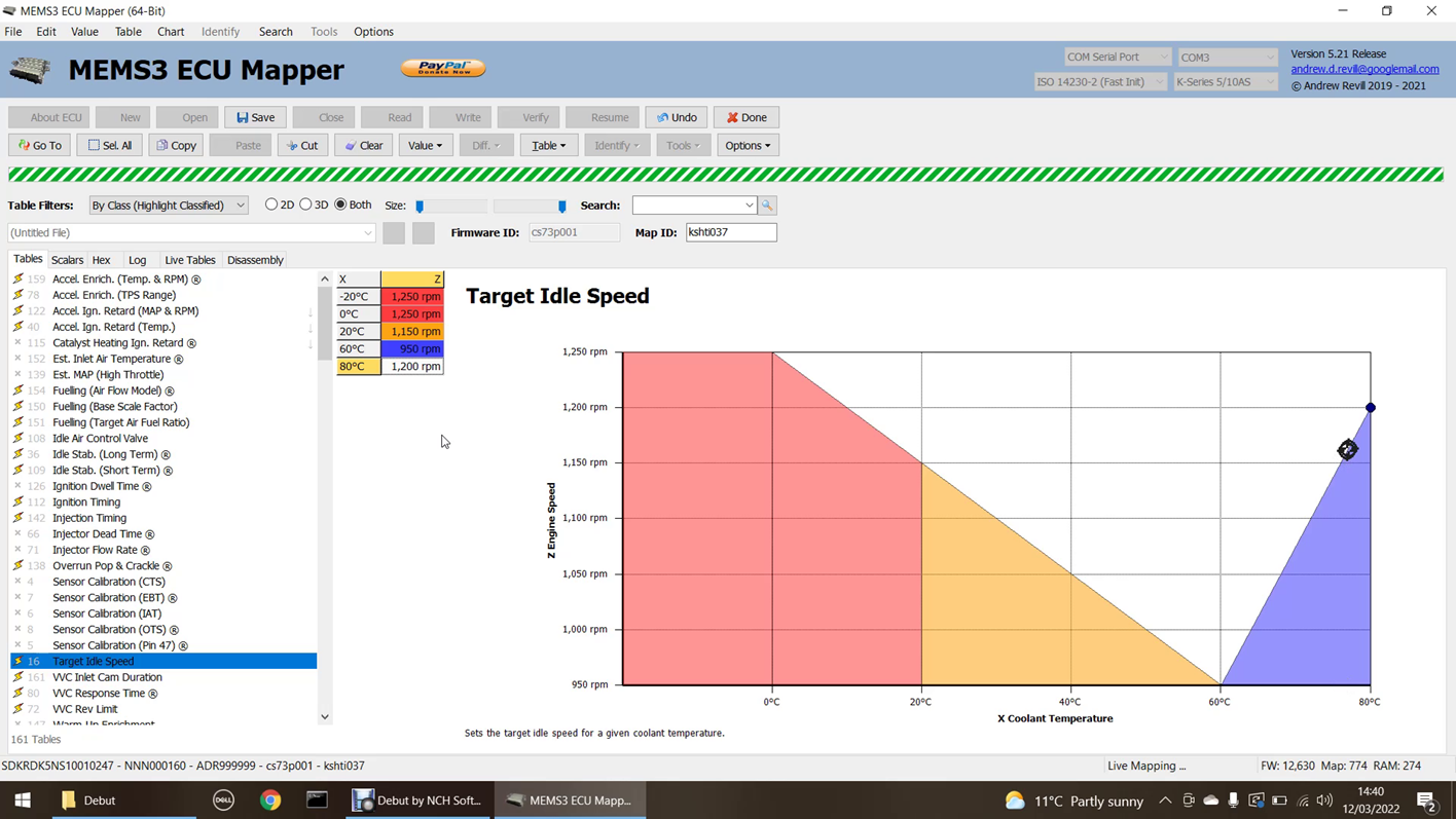
You can see that the ECU immediately started seeing the new values, and you can just hear on the video that the engine idle speed did increase promptly to the new target value.
In the demo video I also demonstrated making some drastic changes to the fuelling:
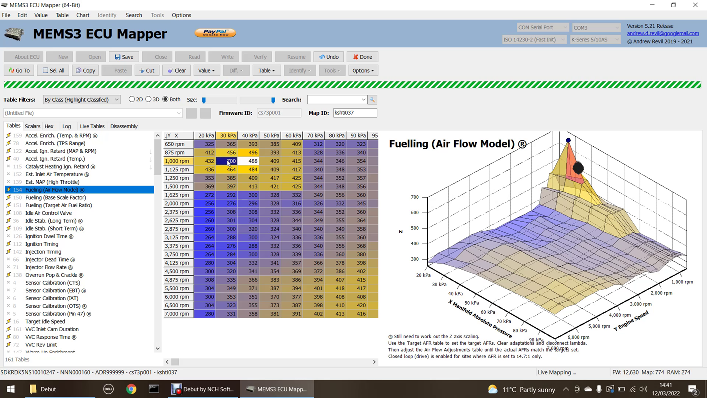
In this case the engine promptly started to idle poorly and smell extremely rich, as expected.
I also modified the VVC inlet cam duration at idle speed from the default 225° to 260°. You can hear in the video that the engine immediately developed a typical “hot cam” lumpy idle, with the fluctuating manifold pressure (as seen from the trail of hits on the chart below) usually associated with large cam durations and overlaps.
The changes I’ve made here have been quite dramatic and a bit silly; I just wanted to be able to make changes that were significant enough to demonstrate they were being uploaded to the ECU in real time, with the engine running, and having the desired effect. On a rolling road you’re much more likely to be making small, incremental changes to different region of tables such as the fuelling, ignition timing and VVC duration, while monitoring the results, listening for detonation issues etc.
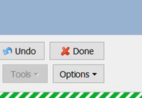
Once you’re happy with the changes you have made, you can end the live mapping session with the ECU. To end the live mapping session, just click the Done button:
The live mapping session will terminate and both the ECU and MEMS Mapper will return to normal operation. You should see a reminder as shown below:
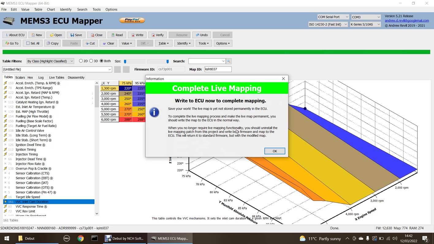
At this stage, the finished map in the MEMS3 project and in the temporary RAM copy on the ECU. The copy on the ECU is not permanent and will be lost the next time the ECU is reset. To make it permanent, you should save your work and then write the map to the ECU in the normal way. This will write the map permanently into ROM on the ECU.
If you want to continue live mapping where you left off, simply start a live mapping session again. Even if the ECU has been powered off and has lost the changes made so far, these are automatically uploaded again when the new live mapping session starts, allowing you to continue working on the map from the point you reached previously.
Once you have finished with live mapping, it would be good practice to remove the live mapping patch from the ECU. There is no need to keep the live mapping patch installed on the ECU once the finished map has been written to it. To remove the live mapping patch, simply write a clean copy of the original firmware, with the finished map, to the ECU. The easiest way to do this is just to uncheck Install Live Mapping Patch under the Tools, Project Tools menu; this will uninstall the live mapping patch from the firmware in the project, leaving it in its original state. You would then write both firmware and map from the project to the ECU in the normal way.
What Happens if I
Write Invalid Values to the ECU?
The software does not have enough understanding of the way in which the ECU will use each of the tables and scalars to provide any protection against writing back values which the ECU will not accept. Invalid values in tables are generally handled better than invalid scalar values, which are in effect just the raw constants used in the program code. If you do enter a value that the ECU cannot handle, it is quite likely to result in the ECU crashing. The engine will either shut down, drop into a mode where it just limps along very badly, or the ECU will reboot cleanly but will no longer be in live mapping mode and will have reverted to the original map (in which case MEMS Mapper will detect the loss of communications and end the live mapping session).
If this happens, remember that the live mapping changes are only temporary and in RAM at this point; all you need to do in the worst case is to power the ECU off and back on again, at which point it will start running with the original map values again. When you next start a live mapping session, the latest changes to the map in the MEMS Mapper project will be uploaded to the ECU again, bringing it back to where you were without losing your work. Make sure you correct the invalid value which caused the problem before resuming live mapping, or it may just crash the ECU again! You can do this using the Undo button.
What Happens if I
Lose Connection?
As described above, if anything happens which causes you to lose connection with the ECU, for example if the ECU crashes or is reset, or the mapping cable becomes disconnected, the latest map with all of your work will still be in the MEMS Mapper project. When you next start a live mapping session with the ECU, all of these changes are uploaded back to the ECU at the start of the session, allowing you to continue from exactly where you left off. It is worth saving the project occasionally in MEMS Mapper as that is the only permanent copy of the map you have.
What Do I Need to
Write Back?
The live mapping patch is a modification to the ECU’s firmware. It also adds features (metadata) to the model, therefore after installing or uninstalling the patch you need to write back both the firmware and the map to the ECU for the changes to take effect.
When changing the selection of tables made available for live mapping, only the map is affected (the map contains a list of live tables and the RAM addresses assigned to them), so after selecting a new set of tables you only need to write back the map.
When changing the selection of scalars made available for live mapping, the changes are implemented by modifying the firmware instructions that reference those scalars. So in this case, you will also need to write back both the firmware and map for the changes to take effect (you cannot write the firmware alone).
When changing values in tables or scalars, the changes are written back to the RAM copy in the ECU if a live mapping session is in progress. If not, they are written back to the RAM copy in the ECU the next time a live mapping session is started. Neither of these are permanent, and if the ECU reboots they will be lost. The latest copy of the map is always in the MEMS Mapper project. Once live mapping is complete, you should save the finished map and you need to write the map back to the ECU in the normal way. If you no longer need to use the live mapping patch, it is probably a good idea to write the standard firmware back too. This can be done by loading a saved copy of the original firmware, or by simply unchecking Install Live Mapping under the Tools, Project Tools menu, which will uninstall the patch and revert the firmware to its original state.
How It Was Done …
Intercepting Table
& Scalar Access
It was quite clear that the ECU did not have enough RAM to allow the entire map to be moved to writeable memory. There are however only a fairly small number of tables and scalars that you would want to edit during a typical live mapping session, so I reasoned that it should be possible to move sufficient tables and scalars into RAM to provide a useable solution. The challenge for me though was that the ECU uses a single register A5 to point to the map in memory, and all references to tables and scalars in the code are written as offsets relative to A5, so it was simply not possible to locate different parts of the map in different areas of memory given the way the ECU firmware was written. I spent a lot of time looking at different solutions:
· Tables were quite easy to handle. All table values are looked up from the map by one central function. This function did vary a little bit between firmware versions, but was always similar enough to allow me to search for it and confirm that I had the correct location. It turned out that there were actually two different main versions of this function, one used on normally aspirated ECUs and one used on turbo ECUs, so I provided code that could search for and identify both variants. I could then patch this function to redirect to a modified copy in my own code. This could look up the requested table index in a table of its own, to identify whether it was to be redirected to RAM. It could then look up the value from the appropriate copy of the table, in either ROM or RAM. It could also send appropriate communications messages over the OBDII port to drive the “Live Tables” and “Table Hits” displays.
· The problem was how to handle scalar values. For these, there is no central function to access them, they are just constants in memory locations which can be accessed by arbitrary code.
o In most ECUs, register A6 (which is normally reserved by compilers as a stack frame pointer) was unused. One possibility was to update the instructions that referenced the tables and scalars I wanted to be able to live-map to use A6 instead of A5, and then point A6 to a copy of the map data in RAM. But there are literally hundreds of different firmware version for MEMS3 out there, and a few of these seemed to use A6 for specific purposes, which meant that this method would not work reliably on all MEMS3 units.
o I could point A5 at a non-existent memory location. This would cause an address fault error every time the ECU tried to access a value in the map. I could then write an address fault exception handler, which could work out what the instruction that caused the fault was trying to do and then execute an alternative, using the redirected map address, before returning to continue execution. This was very complex and a bit of a learning curve, but I did eventually get it running. It sort-of worked, the code executed exactly as I intended, but the problem was that the sheer number of exceptions being generated and handled, and the time it took to push all of the state to the stack, execute the exception handler and then restore the state and continue meant that the time taken to execute one pass of the ECUs main loop was a lot longer than normal; it all looked good on the bench but when I actually tried running an engine with the ECU, it clearly wasn’t running normally. The ECUs response time was just too sluggish and the idle speed was hunting up and down. If this was to be used for mapping the ECU, it was critical that the ECU ran normally with live mapping installed to ensure that the final map ran as expected under normal conditions.
o At this point I was close to feeling I was beaten. I came up with one last plan:
§ I could write some code to analyse all of the firmware versions I had in my library (a lot now).
§ I could make a list of all the different instructions used to access scalars across the full suite of ECUs.
§ I could then generalise these into classes of instructions to predict what instructions were likely to be found on other ECUs that I hadn’t seen yet. For example, the specific instruction which loads a Word sized value from a specific offset relative to A5 into register D0 is an example of the class of instructions which load Word sized values from arbitrary offsets relative to A5 into arbitrary data registers. All of these instructions will be of the same size and will follow a pattern whereby just certain bits of the opcodes vary to indicate the address and the register number.
§ I could use these class definitions to develop code which was capable of identifying and rewriting all of the instructions which accessed a given scalar.
§ I had to come up with a scheme that rewrote each area of the firmware which accessed a given scalar in exactly the same number of bytes of code as was used by the original code, in order to allow the replacement code to simply replace the original code without moving anything.
§ The replacement code also had to have exactly the same effect on all registers, memory addresses and status flags as the original code. Some cases proved to be particularly challenging, but in the end I managed and ...
§ IT WORKED! So I now had a way of intercepting ECU access to any given set of tables a scalars and redirecting them to RAM copies.
· This has all been written using the custom patch framework I had already developed within MEMS Mapper. So it should work on ANY MEM3 ECU. When you apply the software patch, and as you select tables and scalars for live mapping, on the fly it rewrites the ECUs firmware code, potentially in several thousand places, based on analysis on the fly of the existing code rather than any assumptions about the existing code structure, addresses etc., in such a way as to implement a RAM copy of the table or scalar which will leave the ECU running quite normally. It also adds code to the ECU’s startup routine to copy the initial values of the tables and scalars from ROM to RAM, and they can then be modified in RAM with the engine running.
Communications
Protocols
Standard OBDII communications take place at either 9600 or 10400 bits per second. They operate on a request-response basis, where the OBDII terminal sends a request to the ECU, which then responds. The ECU never sends messages other than in response to one sent the OBDII terminal. It quickly became clear that this kind of protocol just wasn’t going to give me what I needed for the “Live Tables” and “Table Hits” displays. Even when sending only one byte for each table accessed, the data rate far exceeded the 10400 bits per second available. In addition, for a real-time display, the ECU needed to be free to send the live information in real time as and when tables were accessed, rather than in response to a request message.
This meant that I had to write my own custom communications suite for the ECU, to support protocols which met my requirements. There were quite a few challenges in this though, over and above the actual protocol requirements:
· The microcontroller in the ECU has an SCI (Serial Communications Interface) component. The Input (RX – Receive) and Output (TX – Transmit) lines from this are effectively tied together inside the ECU, to provide one single, bidirectional data line. In order to reject the high levels of interference which can be coupled onto the OBDII lines in the noisy environment of a running car engine bay, this line is quite heavily filtered to reject frequencies higher than those needed for the regular OBDII communications. Looking at the signal on the SCI pins on the microcontroller, when fed with a high frequency square wave, at much higher speeds the square edges quickly became very rounded and this led to errors and a breakdown in communications.
· The ECU firmware has code which accesses the SCI in many places. As the standard communications are interrupt-driven (the SCI sends an interrupt signal to the microcontroller when certain conditions occur, such as a byte being received, transmission complete or a timeout, and the microcontroller then changes the SCI configuration in response, for example loading another byte into the transmit buffer), it was very difficult to be able to isolate the SCI from all of the native code. It would not work properly if the SCI was triggering the native interrupt routines in response to changes which my code should have been handling. And as this had to work across all MEMS3 ECUs with widely differing codebases, I had to write software which analysed the firmware looking for SCI access and rewrite those parts on the fly to allow me to redirect.
· I couldn’t just redirect all native access to the SCI, because it was important that I could switch the ECU back into normal communications mode when I had finished with live mapping. Without this, the ECU would have been left in a confusing state where standard OBDII tools would not be able to communicate with it. It would also make it difficult for me to be able to write the finished to the ECU using the normal OBDII communications already developed. So I had to find a way that allowed me to switch on and off the native access to the SCI. But this also brought other complications; I needed to make sure that I backed up the configuration and status of the SCI when I switched protocols in order to be able to reset it back to the same state, to fool the ECU into continuing communications as though nothing had happened, and even then I found things didn’t work properly; there was code in the main execution loop of the ECU that was monitoring the SCI and which appeared to abandon all future attempts to communicate if the SCI appeared to malfunction. When running a custom protocol, with all native access to the SCI registers being redirected to unused memory locations, I have to write some extra code that would execute on the ECU to make those locations behave as though they were SCI registers. In effect I had a write a fake, simulated SCI.
· Once I had worked around all of the above, I came to the conclusion that I needed 3 separate custom communications modes, in addition to normal OBDII communications:
o A request/response mode. This would work in a similar way to standard OBDII communications, but by having my own custom mode I could more easily add my own commands to implement custom functionality. For robustness, I implemented this at 9600 Baud, as for OBDII. This mode used a custom message header and checksum.
o An all-tables broadcast mode. In this mode, the ECU would send a message whenever any table was accessed. I was only able to get reliable communications up to 72800 Baud, as beyond that the filtering mentioned above caused problems. Even at 72800 Baud communications were not 100% reliable. But I figured that since this mode was only going to be used to drive the visual indication of which tables where being accessed, and the effect of a garbled message would just be one brief flicker on the display, it didn’t really matter. When I checked the rate at which the tables were accessed, 72800 Baud was only really enough to send single byte messages, with no headers or checksums. So each time a table is accessed, the ECU sends one byte which is the index number of the table in this mode. This mode operates on a broadcast basis; there is no request sent to the ECU, it initiates transmission itself in real time as each table is accessed.
o A single-table broadcast mode. In this mode, the ECU would send a message whenever a specific table was accessed. The table of interest would be specified when entering this mode. Again this mode was to operate at 72800 Baud, but with only a single table under observation there was enough bandwidth for a properly structured message, with header and checksum, carrying details of the table accessed, the X and Y values being looked up and the Z value returned. This mode also operates on a broadcast basis.
· This left a problem to solve. In either of the broadcast modes, the ECU was “talking” almost all of the time. It was not therefore possible to send a message to the ECU, as the transmit and receive lines were tied together. There was only one channel, and as there was no protocol which allowed the two ends of the conversation to take turns, they would simply transmit over the top of each other and so the messages would just be garbled. I solved this by realising that the way in which the transmit and receive lines were tied together meant that the SCI receive section could “hear” the transmissions of the transmit section. OBDII communication lines are designed to be wire-ORed, which means you can connect two transmitters to the same line and if they both talk at the same time, they won’t do any damage to each other (the line is pulled to a high voltage by a resistor, and transmitters only act pull the line down to a low voltage when sending a “0” signal, just letting it float high on the resistor to send a “1” signal, so if two transmitters try to send a “1” and a “0” at the same, they don’t fight as the “1” transmitter just does nothing). So if I arranged the code to guarantee that a message would be sent every N milliseconds (by inserting a dummy keep-alive message if there was ever a break of N milliseconds) I could tell the receiver section to look for a gap of more than N milliseconds without a message. This meant that if I pulled the OBDII line to ground for more than say 2N milliseconds over the serial cable, this would effectively block the receiver from hearing the transmissions and it would know that I was trying to get its attention. So I coded it such that a break signal sent in this way would cause the ECU to drop out of either of the two broadcast modes into custom request/response mode and wait for a command. I implemented commands in the custom request/response protocol to tell the ECU to enter each of the two broadcast modes and to return to standard communications, and I extended the native table inside the firmware which processed the “Execute Routine By ID” OBDII command to add my own command routine, which switched from standard OBDII communications mode into custom request/response mode.
· Getting all of this working was one of the hardest challenges I faced in developing the live mapping system. It all works nicely in the end though. When you start a live mapping session the ECU switches into custom request/response protocol and as you move between the different tabs in the user interface, break signals and custom commands are used to switch the ECU into the correct mode needed to drive that tab. I even implemented a “try connect” system which allows it to pick up communications with the ECU when it is left in an unknown state after communications have been interrupted. This attempts communications with the ECU under each of the protocols, using breaks to try to pull the ECU into a known state from where it can resume communications. When you end the live mapping session, the ECU drops neatly back into standard communications mode and none of the native code even realises that communications were interrupted, it just assumes that no OBDII messages were sent for a period of time, allowing you to write the finished map to the ECU or talk to it with a diagnostic scanner etc.
Disassembly Files
To implement a lot of the above, I was forced to search for particular instructions in the firmware and replace them. Unfortunately, instructions are just sequences of numbers in ROM, and those same sequences of numbers can also appear in data. There is therefore a small but real possibility of patching data instead of code. I coded the pattern matching to be as specific as possible in order to minimise this risk, but the only real way to eliminate it completely is to fully disassemble the firmware, which would give an insight into exactly which addresses were code and which were data. This is a very difficult task. There was no way I was going to be able to write a full disassembler inside the mapper. There are a couple of good commercial disassemblers on the market, e.g. IDA and Ghidra, but these are very large complex software projects in their own right and even then they need quite a bit of manual intervention to get it right, they’re more of a guide tool to help a competent programmer disassemble a piece of software. In the end I came up with a compromise:
· I would use IDA to disassemble all of the firmwares I have copies of, and provide the disassemblies as part of the tool.
· I would code the pattern matching algorithms to avoid false matches wherever possible.
· Where a disassembly was provided for a given firmware, I would write the code the cross-check all of the instructions it was patching with the disassembly file for safety.
· I would store the disassemblies as separate files in a folder; that way, if anyone needs to add a disassembly for a new firmware version, they can either use IDA to prepare a compatibly disassembly file (I’ve provided detailed instruction in a document in the folder which should allow anyone with access to IDA to do this) or they can ask me to prepare a disassembly, which can just be dropped into the folder for immediate use.
The disassembly files, where found for the current firmware, are used for the following:
· To verify that the disassembled instruction at a given address matches the expected instruction when patching binary patterns to replace one instruction with another.
· To verify that the disassembled instruction at a given address matches the expected instruction when pattern matching to identify the locations of given routines within the firmware.
· To identify all instructions which access RAM, and to deduce from analysis of these what RAM addresses are actually in use for a given firmware.
· To identify all instructions which access scalars in the map, and to deduce from analysis of these whether the scalars at given addresses are Byte, Word or Long sized.
Some features, such as the installation of custom software patches, are more reliable where a disassembly file is present, however they may still be used without a disassembly file. But the disassembly file is the only reliable source of information about the data sizes and array structures of scalars. As it is critical to ensure that the whole of a scalar, where it larger than Word size (either Long size or part of an array) is redirected consistently into RAM, all Scalar values are treated as Word sized and LIVE MAPPING OF SCALAR DATA IS DISABLED where no disassembly file is provided. Live mapping of table data is still supported.
Available RAM Ranges
The ECU has very little RAM (memory which can be read and written while the ECU is running, which is used for all of the variables and state of the ECU and which must also be used to store the live tables and scalars).
I did some research on different ECU firmwares to try to determine the RAM address ranges which they used for different things, to see if I could work out what was available. The normal OBDII protocols allow you to read ROM memory addresses, but they do not allow you to RAM addresses (or addresses within the boot loader area of the ROM). I added support for reading these areas in my custom protocol. I noted that the ECU clears all of RAM to 0 values on startup, so my plan was to look for large areas of RAM that still contained all 0s. Individual RAM locations that contained 0 did not mean that they were not used, they may have been used to stare the value 0, however it seemed unlikely that large ranges of consecutive RAM addresses would remain at 0 if they were actually in use, and patterns soon became clear. I used the custom communications routines to dump the contents of RAM after the ECU had been running for a while, and used the dumps to produce maps in Excel of what was used and what was unused. Here are some examples taken from different firmware versions:
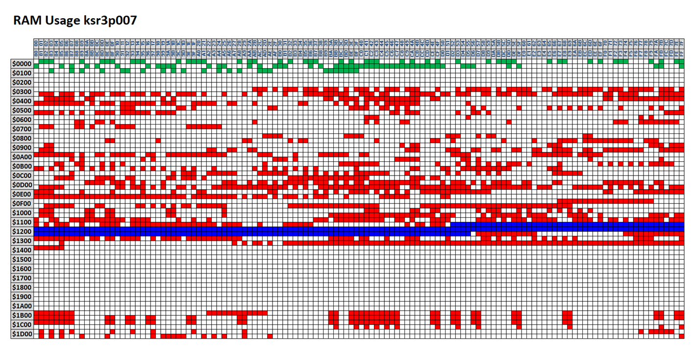
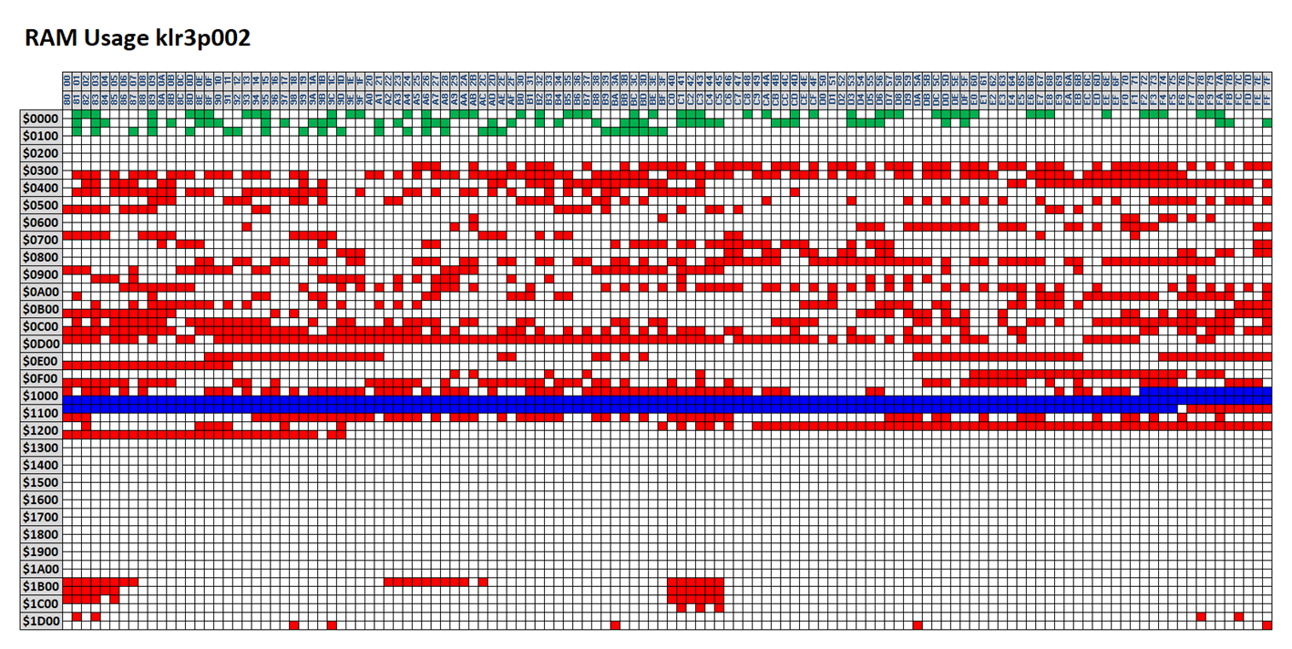
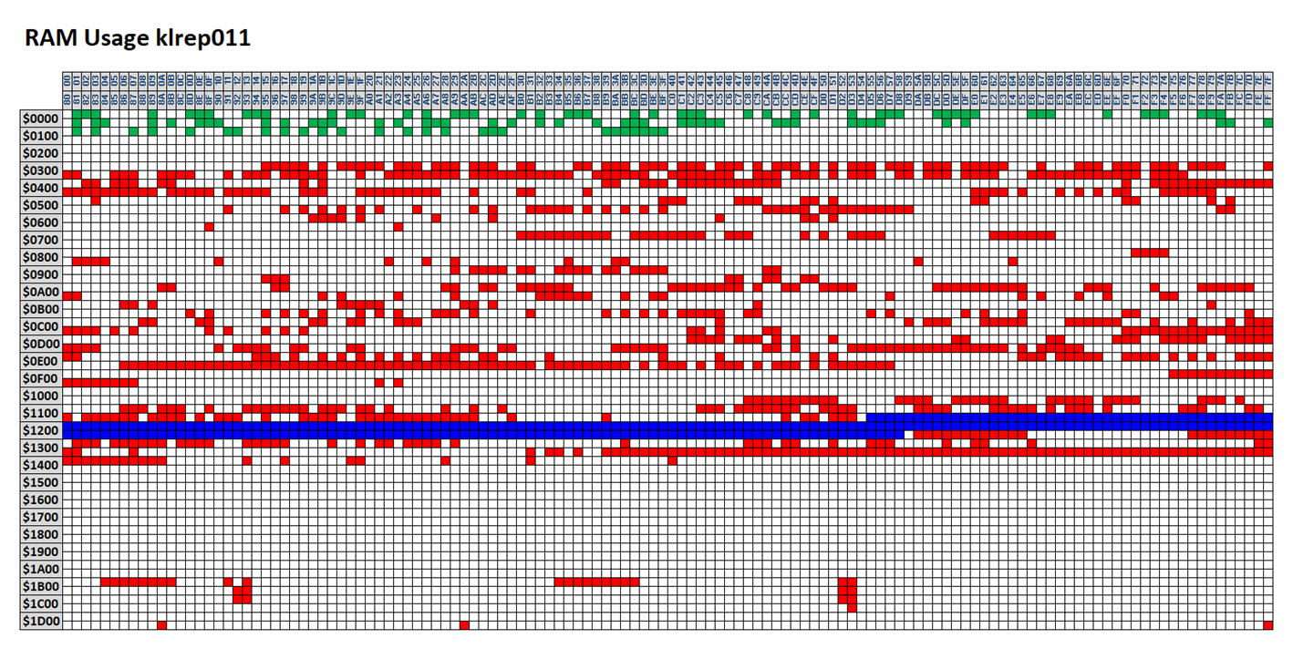
And here is what I got when I combined the maps from all of the different firmware versions:
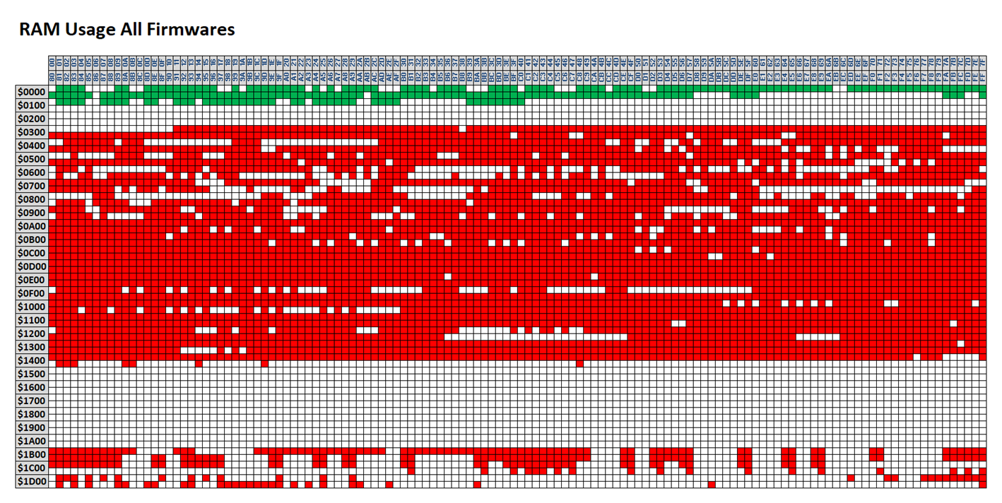
Red addresses represent non-zero values, white addresses represent zero values. By looking across all the firmwares, and looking at firmware disassemblies, I was able to deduce the following:
· RAM addresses below $0400 were reserved for the stack. The stack on an MC68336 microcontroller grows downwards from the top, starting (in this case) at $03FF, allowing 256 bytes of stack space. At no point on any firmware did I ever see that the stack had grown down into addresses below $0300, so the 256 bytes provided by the compiler was actually a much more generous allowance that was required during normal operation. I therefore felt safe enough to use the 128 bytes from $0000 to $01FF for my own purposes. I used this RAM area for my own working variables, which are the addresses shown in green on the maps above.
· The compiler then allocated all of the static variables at consecutive addresses from $0400 onwards. In different firmwares, different addresses were used for different things, but in none of them did it appear that the variables consumed addresses beyond $1500.
· Addresses from $1B00 were also in use. From looking at disassemblies of the firmware code, I think that the compiler allocated mostly single-valued, scalar variables from $0400 onwards and mostly array variables from $1B00 onwards. Whatever the exact usage though, I could not assume that addresses beyond $1B00 were available for me to use.
· Within the main block of variables, in every single firmware there was a block of precisely 260 bytes which was unused. These are highlighted in blue in the maps above. I had a pretty good idea what this might be, and inspection of the disassemblies confirmed it; it was the OBDII port communications buffer, which could contain a message of up to 256 bytes plus header, length etc. Once I had worked out what this was, it was quite easy to write code which could recognise the routines in the firmware which managed this; this gave me a method of extracting the address of the buffer from these routines once I had recognised them, and I was then able to recycle this to use as my own custom communications buffer, leaving more of the higher free block of RAM available for live mapping data.
I therefore had the address range $1500-$1AFF available for my own use on any firmware. That’s 1536 bytes, or 1.5 kilobytes. Not a lot, but enough, with care.
Where a disassembly file is available for a given firmware (see above) it is possible to analyse exactly which RAM addresses are in use and this may result in a larger contiguous block of RAM being made available for live mapping data. Where no disassembly is found, the above 1.5 kilobyte block is used a safe fall-back.
Data Size Limitations
Given that there are only around 1.5 kilobytes of RAM available and that a typical full MEMS3 map may be 12 kilobytes in size, there is clearly no way that the entire map can be made available for live mapping at the same time. On most ECUs however, there is easily enough RAM available to make available all of the tables which you are likely to want to manipulate during a live mapping session.
In addition to the limited amount of RAM, there are also limitations associated with limited available space in the firmware and map areas of ROM too. The three memory areas are used as follows:
· Firmware Space: All of my custom firmware patches are written in a way which allows them to be uninstalled from an ECU without having a copy of the file read from the ECU before the software patch was installed. All changes made to the firmware are recorded in a compressed data block in the unused firmware area in a way which allows the original firmware to be recovered. As selecting a scalar for live mapping results in modification of those instructions in the firm ware which access it, these changes also need to be recorded in the compressed data block. This not only supports uninstallation of the custom firmware patch, but allows the instructions to be reverted if the scalar is deselected. For this reason, each scalar selected for live mapping consumes a small but variable (because the number and sizes of instructions accessing each scalar varies, and because of the compression applied to the data block) amount of firmware space. You will not be able to select more scalars for live mapping than can be accommodated given the available free firmware space, although this is extremely unlikely to be a real limitation in practice. Selecting a table for live mapping does not consume firmware space.
· Map Space: A master list of all live mapping tables and their redirected addresses in RAM is added to the map. For this reason, each table selected for live mapping consumes 10 bytes of map space. You will not be able to select more tables for live mapping than can be accommodated given the available free map space, although this is extremely unlikely to be a real limitation in practice. Selecting a scalar for live mapping does not consume map space.
· RAM: Both tables and scalars consume an amount of RAM equal to the size of the data associated with the table or scalar.
When the live mapping patch is installed in a project, MEMS3 Mapper will show you a running total of the remaining available firmware, map and RAM space as you select tables and scalars for live mapping.
Feedback & Help
If anyone tries this out and has any feedback, please get in touch with me at andrew.d.revill@googlemail.com.
Similarly if anyone wants me to help setting up a car for live mapping, please do get in touch.