MEMS3 Flywheel Trigger Pattern
Changes
Download
Link: https://andrewrevill.co.uk/Downloads/MEMSTools.zip
Using my MEMS Mapper you can now
easily adjust the map to work with a different flywheel trigger pattern.
This follows on from the work I did on
allowing a MEMS3 from a Rover 75 or MG ZT to run without its matched BMW EWS
immobiliser. The driver behind this was to allow an MG ZT-T engine and ECU to
be transplanted into say an MG ZR. Having solved the immobilisation issue, it
was then pointed out to me that the MG ZT uses a completely different flywheel
and gearbox to other K Series installations and the flywheel trigger pattern
was also different, so a ZT ECU would not run with a ZR flywheel. So I set
about hunting for the code that managed the flywheel tracking, wondering if I
would be able to figure out how to change the pattern. To be honest I was
expecting this to be a hard one, and I read up on the
TPU (Time Processing Unit in the MC68336 microcontroller) ready for a fight …
but once I started to dig into it, the answer was actually quite simple, as
I’ll describe later in this article. In the meantime …
By following the instruction below, you
will be able to tell the MEMS3 ECU about the new flywheel trigger pattern so
that it will then synchronise correctly.
This may be of direct use on a Caterham
when upgrading an early MEMS 1.9 engine to MEMS3 without swapping the flywheel.
Basic Instructions
You will need to download the latest
version (5.56 or later) of my MEMS Tools from here: https://andrewrevill.co.uk/Downloads/MEMSTools.zip
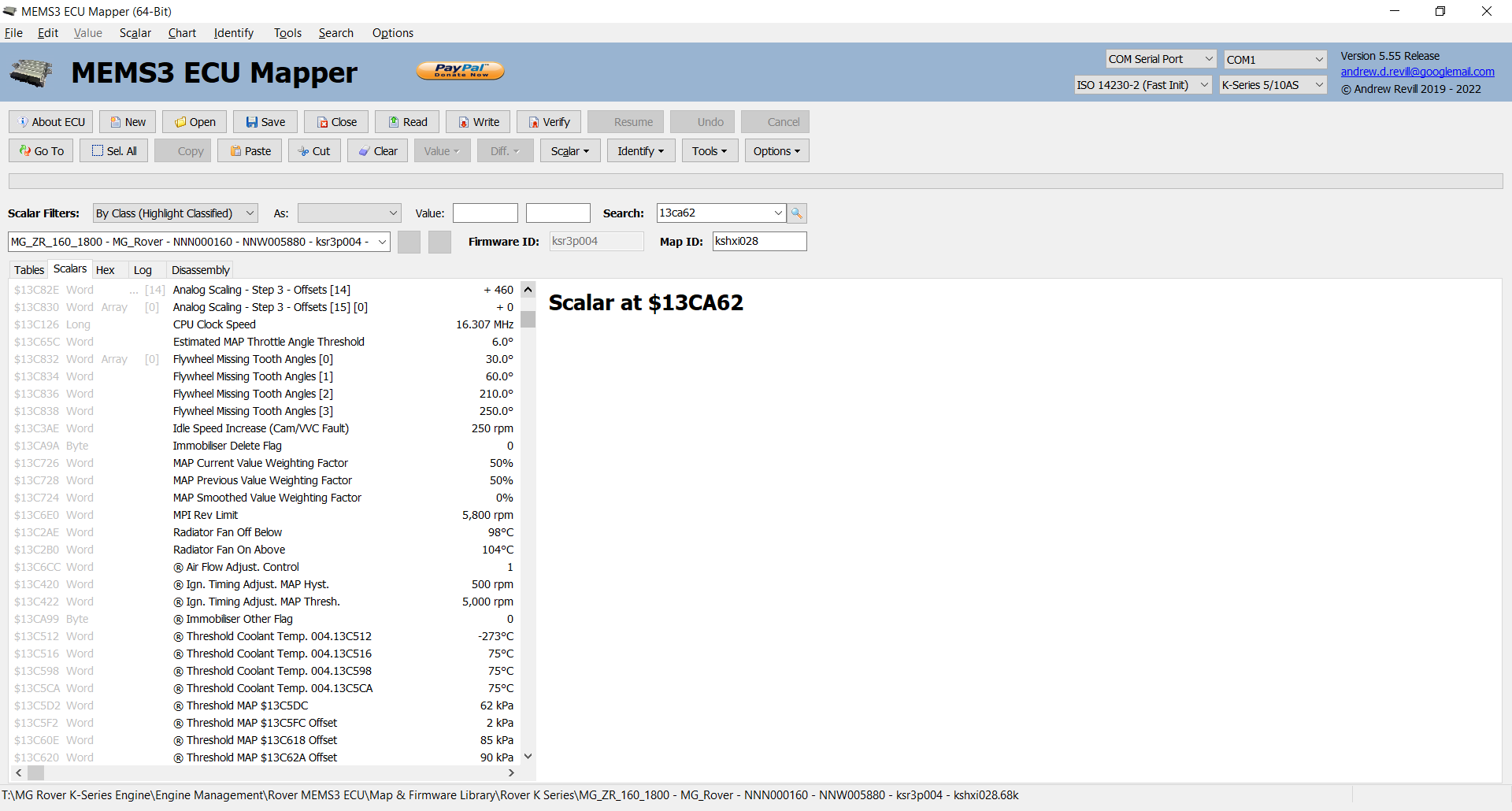
If you open a file or read the map from
an ECU using this version you should see some scalars listed, with descriptions
“Flywheel Missing Tooth Angles[0]” to “Flywheel
Missing Tooth Angles[3]” as shown below.
If you are using a firmware version that
I haven’t seen, these will not be found. In that case just click Identify,
Keep Existing and it should find them all automatically.
All you need to do is enter the new
missing tooth angles, in degrees ATDC in increasing order, into these four
scalars.
Just to make it a little more convenient
to edit and validate them in one place, and to allow you to select from a
number of predefined flywheel patterns, I’ve added a wizard to do it for you.
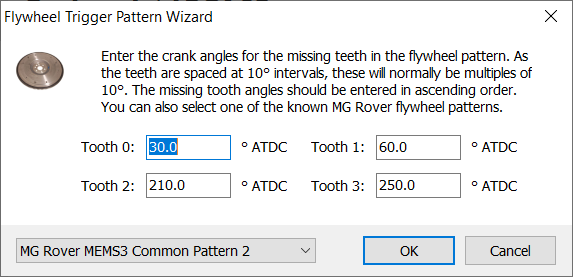
Click Tools, Wizards, Flywheel Trigger
Pattern and you should see a dialog like this:
If this menu
item is disabled, the application has not been able to identify the relevant
scalars in the map. Ensure that you have used the Identify, Keep Existing system to identify the scalars.
In this
dialog you enter the four missing tooth angles, in ascending order. You can
also just select one of the standard flywheels from the combo box to populate
the dialog with the correct numbers. Standard flywheels provided include the MG
Rover MEMS 1.9 Common Pattern (0°, 120°, 180°, 310°), MG Rover MEMS 2J/3 Common
Pattern (30°, 60°, 210°, 250°) and Rover 75 or MG ZT Specific Pattern (80°,
120°, 270°, 300°). As the patterns are all based on 36 teeth, the teeth are
always spaced at 10° intervals and the tooth angles are normally integer
multiples of 10°.
If you are
using a different flywheel and you have some numbers, please let me know and
I’ll add it to the list.
When you’re done, click OK to
update the current map. If the OK button is disabled it means that the
angles entered are invalid, for example duplicated or out of order.
This wizard is compatible with live
mapping mode and will let you play with the flywheel trigger pattern on a live
engine.
Technical Details
I original expected this to be a hard one
to find.
Inside the MC68336 microcontroller in the
ECU is a Time Processor Unit (TPU). This turns out to be very flexible and
powerful. It has 16 channels, each of which can be programmed in microcode to
perform a different timing function. Channel 0 is programmed to track the crank
sensor signal and generate interrupts with the passing of the teeth that allow
the CPU to track the flywheel position. Channels 1 & 2 are slaved to
Channel 0 and are programmed to trigger interrupts at given points in the cycle
– driving the ignition coils. Channels 3, 4, 5 & 6 are slaved to Channel 0
and are programmed to trigger interrupts at other points in the cycle – driving
the fuel injectors. Most of the timekeeping of the engine is therefore
performed by the TPU alone without direct intervention of the CPU, whose job it
is to monitor conditions and update the parameter of the TPU.
I went looking for the coding of the flywheel trigger pattern in the TPU management, following examples such as this: Period Measurement With Missing Transition Detection TPU Function (PMM), by Motorola / Freescale / NXP who make the microcontroller. Following the examples, one of the first things I looked at in the ECU code was the routine that handled the TPU interrupt for TPU Channel 0, and that led me to the routine that manages the internal RAM variable for Crankshaft Rotation Position, which starts off like this:
*************************************************************
*
* FUNCTION
*************************************************************
undefined funProcessCrankshaftRotation ()
undefined D0b:1 <RETURN>
undefined2 Stack[-0x2]:2 local_2 XREF[2]: 0011127a (*) ,
00111280
(*)
funProcessCrankshaftRotation XREF[1]: FUN_00110d4a:00110dfa (c)
00111120 70 05 moveq
#0x5 ,D0
00111122 32 35 03
move.w (0x832 ,A5,D0w *0x2 ),D1w
20 08
32
LAB_00111128 XREF[1]: 00111132
(j)
00111128 6c 0a bge.b
LAB_00111134
0011112a 53 40 subq.w #0x1 ,D0w
0011112c 32 35 03
move.w (0x832 ,A5,D0w *0x2 ),D1w
20 08
32
00111132 60 f4 bra.b LAB_00111128
LAB_00111134 XREF[1]: 00111128
(j)
00111134 42 47 clr.w D7w
00111136 34 38 04
c6 move.w (varWordCrankshaftRotationalPosition_S21
).w,D2w
0011113a 04 42 00
64 subi.w #0x64 ,D2w
0011113e 3a 3c 0e
10 move.w #0xe10 ,D5w
00111142 da 6d 08
32 add.w (0x832 ,A5),D5w
00111146 32 35 03
move.w (0x832 ,A5,D0w *0x2 ),D1w
20 08
32
…
Straight away I noticed the bits I’ve
highlighted in the above listing. The whole routine is heavily dependent on an
array of scalars at offset 0x832 in the map. And I went to look what was in
that array, there were the four missing tooth angles.
And it turns out the routine isn’t really dependent on anything else, those four tooth angles are all it needs and uses to
track the crank angle.
I don’t have access to a Rover 75 or MG
ZT to test this on, so I had to test it on an ECU test harness.
My test harness generates crank and cam
sensor signals corresponding to MG Rover MEMS 2J/3 Common Pattern (30°, 60°,
210°, 250°). When I flashed a Rover 75 firmware and map onto a test ECU, it
would not synchronise with my test harness at all. The ignition coils and
injectors were firing away but in an erratic pattern, and live diagnostics
showed that the ECU thought it was cranking rather than running; it was
recognising that there was a signal from the crank sensor, but it was unable to
synchronise to it.
When I used the above method to change
the flywheel pattern in the Rover 75 map and flashed it onto the test ECU
again, it synchronised and appeared to be running normally. The ignition was
firing in a regular pattern and the injectors were firing sequentially. But to
be sure, I had to confirm that the engine timings were as expected. To do this,
I took a VVC firmware and map and a Rover 75 firmware and map. In the maps I
took out all of the adjustments applied to the ignition timing and modified the
ignition timing table to hold a constant value at all MAP and RPM values. This
meant that I knew exactly what the ignition timing should be on my test
harness. I was then able to attach an oscilloscope to the crank signal and the
ignition coil drive.
Stock VVC Map:
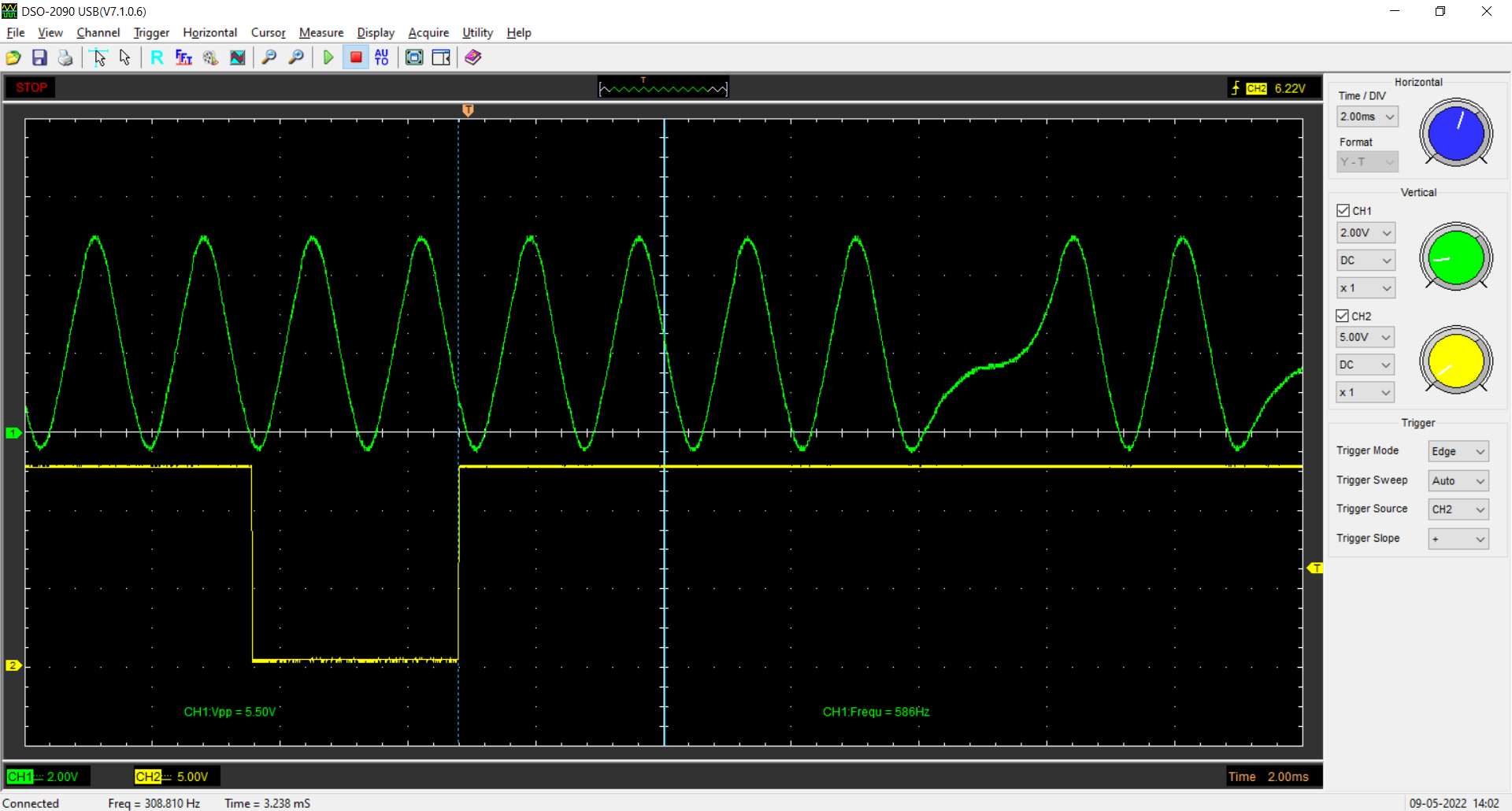
Flywheel-Swapped Rover 75 Map:

These are arranged such that the heavy
vertical scale line in the middle is at TDC. The closely-spaced peaks in the
crankshaft signal are at 10° intervals, so the point at which the ignition coil
fires (the rising edge of the yellow line) is at approximately 20° BTDC, which
is the value I had programmed into the tables. You can see that the
flywheel-swapped Rover 75 map is a very close match indeed for the VVC map, and
so the ECU with the Rover 75 map is now correctly tracking the flywheel
position based on the standard trigger pattern. Similar measurements on the
injector timing also yielded the expected results (after a bit of head scratching;
the very early NNN100683 ECU, which I already knew to be riddled with bugs in
its OBDII code, seems to fire the injectors exactly 10° later than specified in
the map, even with the stock flywheel, but later 75 ECUs behaved as expected).