OBDII Pods – ECU / Immobiliser / Key
Pairing – And Much More
The Problem
I’ve recently started sending out modified remappable MEMS
1.9 ECUs. It’s not easy to send these in a “plug and play” state where they
will automatically pair with an immobiliser when they see one, so I needed an
easy way for people to be able to pair them with their existing immobilisers.
It is possible with my MEMS Mapper and Lucas 5AS tools,
but you need a PC and various cables and some people didn’t have laptops /
weren’t particularly comfortable with the PC applications. So I needed
something really easy.
I also get regular requests to pair standard ECU,
immobiliser and key fob sets for people.
The Solution
So I designed these …

They do the job with just one button press.
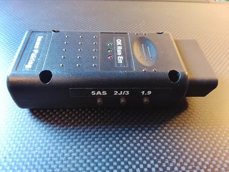
OBDII Pairing Pods
Of course, me being me, I took the thing a whole lot
further …
They work with the MEMS 1.9 ECUs as
originally intended. All you need to do is:
·
Make sure the ignition is on and the
immobiliser is disarmed.
·
Plug the pod into the OBDII socket.
·
Press the “1.9” button.
·
It will beep and the yellow “Run” LED will
come on, telling you it’s busy.
·
After a few seconds this should change to a
green “OK” LED … meaning all done!
·
If you get a solid red “Err” LED it couldn’t
communicate with the ECU for some reason.
·
If you get a flashing red it got an error
code back from the ECU … it flashes in groups and different numbers of flashes
mean different things so you can look up what was wrong.
They also work pretty much exactly the same
with MEMS 2J and MEMS 3 ECUs. Just press the “2J/3”
button instead.
They will also pair key fobs with a Lucas 5AS
immobiliser. Slightly different this time:
·
Press the “5AS” button.
·
Wait until the yellow LED blinks and it beeps
again to tell you it’s ready for keys.
·
Press the lock button on each key fob 8 times
or more (on a Rover the horn will sound briefly after each key isa learned, on
a Caterham unfortunately there’s no feedback).
·
Then press any button on the pod to tell it
you’re finished, the green LED will come on and it’s job done.
If anyone wants to borrow one, just shout.
You can buy one off me if you really want, but unless you’re working with these
cars on a regular basis, they’re the kind of thing you only need once. So long
as they come back safely I don’t mind loaning them out.
Just to be clear, these will work for pairing up ANY of these ECUs with
immobiliser and key fobs, not just my modified remappable ones. So if you are
replacing an ECU and immobiliser and need them pairing up, or if you want to
pair a replacement key fob, these will do the job very easily.
Other Pods
But I designed them as completely generic devices with a
few goodies inside …
They’re really general-purpose OBDII Swiss Army Knife
toolkits.
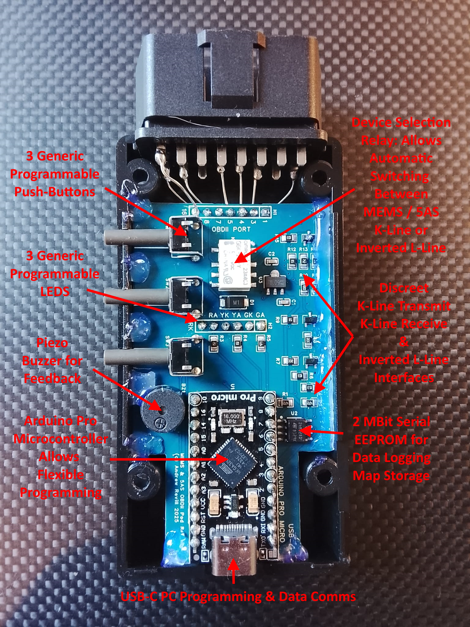
They’re built around an Arduino Pro Micro which allows
easy programming in C. This uses an ATMega32u4 microcontroller, which means
they have TWO serial ports, one used to talk to the OBDII port and one to the
USB-C connection. I’ve written a library of functions which let them
communicate with all of the supported devices. For MEMS 2J/3 they talk
in properly formatted and validated ISO14230 / KWP2000 protocol, so they
can easily handle diagnostics sessions, seed key security routines etc. For
MEMS 1.9 they talk ROSCO protocol, and for Lucas 5AS they talk modified
ROSCO with the odd inverted L-Line reply protocol (the L-Line inversion is
done in discreet hardware, presenting a standard UART signal to the
microcontroller). The on-board discreet electronics can transmit on K-Line,
receive on K-Line and receive inverted L-Line through any of the OBDII pin
combinations used on MG Rover and Caterham cars.
The three buttons, three LEDs and beeper are under the
control of the microcontroller, so can be used to implement a range of simple
user interfaces.
And they have a 2 Mbit serial EEPROM chip built in on the
board. This means they could be programmed to do things like:
·
Record live data logs from MEMS 3/2J/1.9 or
Lucas 5AS. The logs could be downloaded to a PC over USB afterward.
·
“Smart” data logging … watching for a given
fault condition and then logging for a given time period.
o
Which could use a rolling log to record the
bit before the fault happened as well as the bit after.
·
Read and store the firmware and map from an
ECU. The EEPROM is large enough to hold complete read of any of the ECUs.
·
Write a new firmware and map to an ECU
(remote mapping delivery).
·
ECU deep cloning.
·
OBDII map switching.
·
Probably lots of other things I haven’t
thought of yet! Let me have any bright ideas.
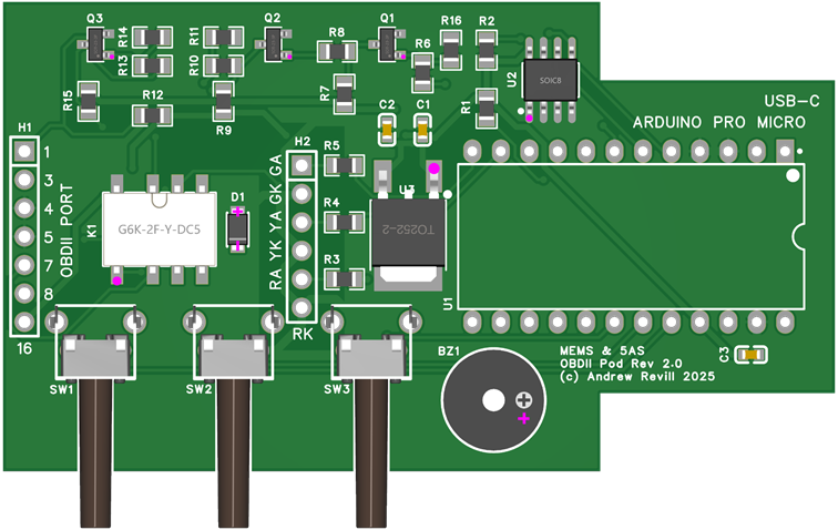
Rev 2.0
The design above is a prototype “Rev 1.0”. I’ve since
designed a production “Rev 2.0” which, amongst other minor enhancements, has
robust external 5V regulator on the board, as I’ve found the tiny internal
regulators on the Arduino board to be a bit fragile, even when stepping the
external supply down from the nominal 12V to 9V externally first. Having said
that … I’ve had ONE fail in these devices, and that was custom programmed and
trying to run a brute-force seed-key crack on another ECU and had been running
for 10 days x 24 hours flat out at the point where it failed, so it was getting
a good hammering!
The Rev 2.0 boards are currently in production in China.
Rev 1.0 and Rev 2.0 boards can both run exactly the same firmwares.