Demystifying the Caterham K Series
Starter Solenoid Circuit
There seem to be a lot of cases recently of problems with the K Series starter circuit, with the starter motor failing to engage (the so-called “K-Click” and similar issues). There also seems to be a lot of confusion as to what can and cannot affect the correct operation of the starter solenoid and motor and how to go about properly diagnosing faults. The starter circuit seems to be a bit of a mystery. This is not helped by the fact that the relevant circuitry is spread across the engine loom wiring diagram, main vehicle loom wiring diagram and the internal schematic of the MFRU, which is very much a black box to many people.
There are a number of “standard” modifications around which aim to cure these problems, but it is important to realise that there are many points where problems could arise and one solution may not fix all.
In the diagrams below I’ve pulled together the whole circuit from the three sources. I have tried to explain both the normal operation of the circuit and a plan for properly diagnosing issues. In reality the circuit really is very simple, nothing more than a battery driving a motor, switched through a relay; there are four relays inside the MFRU but only one of them has any relevance here, so the MFRU is for the purposes of the starting circuit just a single, standard relay.
It is important to notice at this point what is not included in the circuit. There is no involvement of the ECU, immobiliser or any electronic sensors or actuators. The engine management system has no impact on or control over the starter motor operation. It is a straightforward, self-contained electromechanical circuit. If it fails, the cause is to be found somewhere in the wiring shown and not elsewhere.
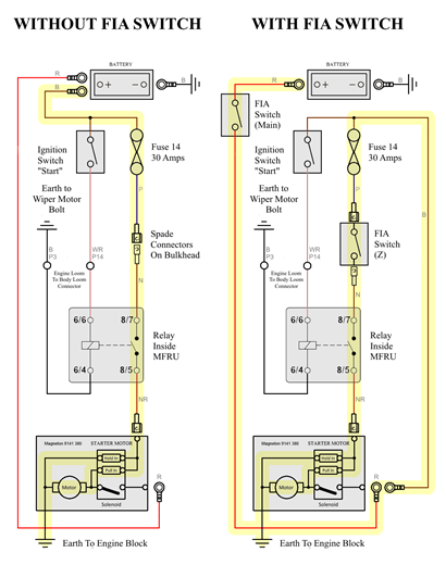
The circuit on the left is most easily understood. This is for the case where no FIA switch is fitted. The circuit on the right is a modified version of the one on the left with the changes which are usually made when installing an FIA switch. In essence the main part of the FIA switch is in series with the battery and the other circuits which would otherwise run directly off the battery are taken off from the starter motor main terminal, downwind of the FIA switch. The “Z” contacts of the FIA switch disconnect the power feed to the engine loom when turned off. Otherwise the two circuits are identical.
The normal failure mode for the starting system is that a click is heard from the MFRU when attempting to start; a further louder click may be heard from the starter motor solenoid, but the motor doesn’t run.
Inside the starter motor solenoid there is a large coil of thick copper wire. This draws a very large current when connected to the battery and generates a large magnetic force, which pulls an iron core into the coil. This does two things. Firstly it operates a lever which pushes the pinion gear on the end of the starter motor into engagement with the teeth of the ring gear on the flywheel. Secondly, at the end of its travel, it closes a heavy duty switch which turns on the motor (and in doing so, turns off part of the solenoid winding as the current required to hold it in place is a lot less than the current required to pull it in initially).
What is normally happening when the motor fails to operate is that the solenoid is not generating enough magnetic force to pull the iron core fully into the solenoid whilst engaging the pinion gear, and is not therefore completing the circuit which switches on the motor.
There are a number of reasons why the motor may not run. These include something physically sticking within the motor mechanism, preventing the solenoid from driving the pinion gear into place, failure of the actual motor itself or the power contacts in the solenoid which turn it on, but in the vast majority of cases the fundamental problem is that the solenoid is simply not generating the pull that it should produce.
There are two main reasons why the solenoid may not produce the desired pull. The first is deterioration of the solenoid itself; the insulation between the windings of the coil can deteriorate with age, effectively shorting out some of the turns of the coil and reducing performance. The second is that the current flowing through the solenoid windings is less that it should be. This is by far the most common explanation.
So, if the circuit is essentially simply, how come it so often fails to supply enough current to the solenoid?
There are two things which make this circuit unusual. One is the very high currents involved. The other is the very small margin for deterioration before the solenoid fails to operate. The solenoid normally draws a current of around 15-30 Amps. At this level of current, even thick solid copper wires cannot be treated as perfect conductors, they have some resistance to the flow of electric current. This means that some voltage is lost along the length of the wire, and the voltage available to push current through the solenoid is lost in pushing current through the wires, connectors, switches, fuse, relay contacts etc. Each of these has some resistance. These resistances are normally very small, but the voltage drop through a resistance is proportional to both the resistance and the current flowing, so at higher current requirements, even small resistances can become significant.
Intuitively one would expect that when connecting the solenoid to a 12.5V battery, you would get about 12.5V across the solenoid. This is not the case. There are two reasons for this. The first reason is that when drawing a heavy current from the battery, its voltage will fall; the battery will no longer be producing 12.5V measured across its terminals but probably more like 11.5V. The second reason is that voltage is dropped through the various resistances around the circuit as described above, meaning that not all of that 11.5V reaches the solenoid (the two reasons are actually one and the same - the battery voltage falls because of voltage drops across resistance internal to the battery). In fact in measurements I have taken on a few apparently health systems, the voltage at the solenoid is typically around 9.5V or less. And as the voltage at the solenoid is reduced, the current that voltage is able to push through the solenoid falls in proportion, as does the magnetic force it produces.
In a research paper entitled “Starter solenoid and power contacts diagnostics” by J. POŠTA, R. PAVLÍČEK, T. HLADÍK of the Czech University of Agriculture, Prague, Czech Republic, the authors examined the performance of a Skoda Felicia starter motor and solenoid system. The Skoda Felicia starter is a Magneton of a very similar design to the 9141 380 used on the Caterham K Series, and uses an almost identical solenoid. They found that external circuit resistances of more than 0.5 Ohms are enough to prevent the solenoid from pulling in at all.
The authors of the paper above also noticed that voltages at the solenoid of less than 7V may lead to failure to operate. Given that in a healthy Caterham installation the voltage is already reduced to around 9.5V, there is not much margin for deterioration.
Knowing that the total resistance in the circuit will be the sum of a number of smaller resistances at various points, the kinds of resistance problems which can cause this issue are very small indeed, and too small to be found and measured directly with any accuracy with the resistance range on a multimeter.
So how should one go about looking and fixing for these tiny additional resistances?
The answer is simple; look for the voltage drops! We have already noted that, although they are very small, when passing a high current these resistances lead to significant drops in voltage, and these are easily measurable. Note the important phrase “when passing a high current” - you will only see the voltage drops when the circuit is intact (i.e. you don’t disconnect things to make measurements) and operating (i.e. you make the measurement while holding the key in the start position briefly, attempting to start the engine).
There are two ways of measuring the voltage drop between points A and B.
In the first method, you measure the voltage between point A and a good ground (e.g. the engine block or battery -ve terminal) with a voltmeter, then you measure the voltage between pint B and the same ground point (this is important, if your ground point is not as good as you think it is you will otherwise be accidentally measuring the voltage drop between your two ground points as well) and subtract the results.
In the second method, you connect the voltmeter directly between point A and point B.
Although these may appear to be equivalent, they are not; in the first case you are not making the two measurements at the same time; the battery voltage will vary with time under load and resistances will change as things heat up. You end up measuring two large voltages (in the 12V range) with two large errors, and when you subtract them the little voltage you are looking for gets lost in the errors.
For this reason, measuring the voltages around the circuit directly is much preferable. So when measuring the voltage drops along a circuit from A to B to C to D, firstly connect the probes of your voltmeter to points A and B and measure the small voltage (probably in the 0.5V range) between them. Then move on to points B and C, then points C and D etc.
The path taken by the solenoid current is highlighted in yellow in each of the diagrams above.
I measured the voltage drops on my car by way of an example. The engine was cold and the battery was freshly taken off a conditioner. I have no starting problems and believe my car to be a reasonable example of a healthy starting system. Here’s how I went about it (in my case I disconnected the main power cable to the starter motor to prevent the motor from starting, otherwise I wouldn’t have been able to take readings before it started):
· I measured the battery voltage, directly across the two terminals of the battery, whilst attempting to crank the engine. It dropped from around 12.6V unloaded to 11.5V while I held the key in the start positions.
· I measured the voltage from the battery -ve terminal to the engine block, to check that I didn’t have a significant voltage drop (i.e. resistance) in the earth path. Since this uses a very hefty cable, there should be very little voltage indeed dropped here. In my case it was only 3 millivolts (0.003V) which seemed healthy.
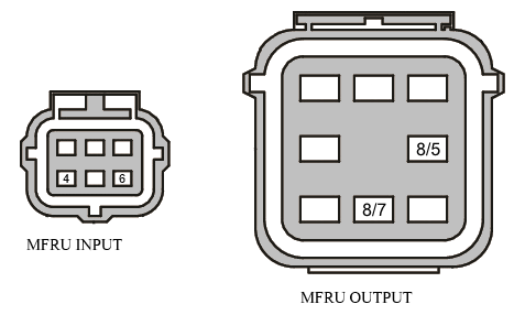
· I then worked along the circuit from the battery +ve terminal to the solenoid, step by step following the path highlighted in yellow in the left hand diagram above (my car does not have an FIA switch - the exact path taken would be different if it did but the principle would still be the same). Firstly I measured the voltage drop from the battery +ve terminal to the input side of the ECU fuse, then across the two terminals of the ECU fuse, then from the output side of the ECU fuse to the female spade terminal, then between the female and male spade terminals, then from the male spade terminal to MFRU pin 8/7, then from MFRU pin 8/7 to MFRU pin 8/5 and finally from MFRU pin 8/5 to the starter motor solenoid terminal. The voltages I got are recorded in the table below:
|
Circuit Path |
Voltage Drop |
|
Battery Voltage while
Attempting to Crank |
11.5V |
|
Engine Block to Battery -ve |
3mv |
|
Battery +ve to ECU Fuse Input |
450mV |
|
ECU Fuse Input to ECU Fuse Output |
230mV |
|
ECU Fuse Output to Spade Female |
290mV |
|
Spade Female to Spade Male |
24mV |
|
Spade Male to MFRU 8/7 Relay Input |
380mV |
|
MFRU 8/7 Relay Input to MFRU 8/5 Relay Output |
320mV |
|
MFRU 8/5 Relay Output to Starter Solenoid |
540mV |
|
Starter Solenoid to Engine
Block |
9300mV (9.3V) |
|
Total |
11534mV (11.5V) |
· A final measurement of the voltage between the solenoid terminal and the engine block showed me that the voltage remaining at the solenoid was only 9.3V.
The laws of physics say that the sum of the voltage drops between any two points in a circuit should be the same, whatever route you take when measuring them. So as a sense check we already know that the voltage drop from the battery +ve terminal to the battery -ve terminal directly was 11.5V - the voltage drops around the starter circuit should add up to about the same, give or take errors in measurements and variations over time. They add up almost exactly to 11.5V so we can be confident we’ve done it right.
To be honest, I was surprised by the result. I was losing voltage left right and centre. For example I was losing 0.54V between the two ends of the heavy gauge wire from the MFRU output terminal to the starter solenoid. I’ve subsequently confirmed the results in detail on another engine and wiring loom with almost identical results, and measurements on a friend’s engine also yielded about 9.0-9.5V at the solenoid, so they look to be fairly normal; just a consequence of the high current demands of the solenoid.
An interesting observation was that of the 2.3V or so lost in total, only 0.32V of that was across the relay inside the MFRU which is commonly held to be the point of failure. Clearly my engine was not suffering problems so this figure may be a lot higher on other cars.
So having established the above numbers as a rough base line for a healthy system, what would we expect to see on an engine that was failing to start and what would it tell us?
First of all I would say this; go about it methodically, work through the plan as I have done above. It only takes a few minutes to get a full set of numbers. Start with the battery voltage unloaded. If that is low, you’ve got a battery problem right from the start. Then check the battery voltage when attempting to crank; if that drops off excessively you either have battery problem or a short circuit somewhere downstream that is drawing a much heavier current (in which case, be careful). Make all measurements with the circuit intact and while holding the key in the start position for a second or two. Don’t hold it too long or the starter will get hot. Be very careful using multimeter probes around the back of the starter motor, there are terminals there that are connected directly to the battery through very heavy cables and they are in very close proximity to the engine block which is grounded. Short circuiting across these could lead to damage or injury.
If at the end of it you find you have a similar voltage to me at the solenoid and it is still not operating, it would suggest that you may have an internal problem with the starter motor itself, either electrical or mechanical. However it is most likely that you will find a significantly lower voltage across the solenoid, and if your battery voltage is healthy then by the physical law quoted previously you will find one or more of the voltage drops to be considerably higher than mine. The section where the voltage drops is the section with the resistance issue, and the cause of your problem.
If it’s along a wire, you may have a problem with the wire itself but more likely it will be a loose or corroded terminal at one end or other. The wire which runs down to the solenoid does get exposed to a lot of radiant heat from the exhaust and can become damaged, but most of the other wires will generally be reliable. I have omitted wiring which is not part of the starter circuit in my diagrams; this does however mean that some of the wires, particularly the brown power supply wires, may have joints inside the loom where other wires (not shown) branch off them. These crimped joints have been known to be poorly formed and have given problems in Rover looms. They are more likely to be a source of resistance than the wire itself, and the loom will need to be carefully unwrapped to access them.
If it’s across an FIA switch, check that all of the connections to the switch are secure. If so you may need to consider replacing the switch.
If it’s across the fuse, consider replacing the fuse and scraping the contacts clean in the fuse box. I have known the resistance of fuses to increase with age, especially where they have been running close to their rated current and getting hot.
If it’s across the relay in the MFRU, replacement MFRUs are
readily available on eBay for around a tenner. Just make sure you get the right
one for your engine as EU2 and EU3 MFRUs were different despite appearing
identical externally. YWB100970 is correct for EU3 engines with coil packs on
top of the plugs. YWB10022 is correct for EU2 engines.
If you find the full battery voltage across the solenoid and
very little voltage dropped elsewhere, the solenoid isn’t drawing any current
and the coil windings are likely burned out. If you find a much higher than
expected (when compared to my results) voltage across the solenoid and much
smaller voltage drops elsewhere, and the solenoid makes a vague click but no
real attempt to pull in, this suggests that the larger pull-in winding of the
solenoid has burned out and only the smaller hold-in winding is operating. This
draws a much smaller current than the pull-in winding. The pull-in winding is
connected to one of the solenoid power contacts and earths through the motor
when it is not being powered; it is therefore possible that pull-in winding
isn’t drawing current because of a failure in the brushes or windings of the
motor itself.
If you are finding that your car is reluctant to start only when hot, for example after leaving it parked for a few minutes after a hard blat (as is often the case with the classic K-Click), you could try to repeat the tests with things hot (but be very careful working around a hot exhaust). The electrical resistance of copper increases markedly with temperature and the solenoid is exposed to radiant heat from the exhaust headers, so can get very hot under these conditions. If there are already other excess resistances in the circuit, the extra resistance of the solenoid can be the straw that breaks the camel’s back. Note that, according to the law quoted the total voltage drops around the circuit must remain equal to the battery voltage, and as the resistance of the solenoid increases it will take a larger share of the voltage drop; so testing hot you will probably see an increase in the voltage across the solenoid rather than a decrease, coupled with a decrease in other drops around the circuit. One or more of these are likely to be excessive when cold though, indicating the source of the problem.
Once you have found the real cause of the problem, you are in a good position to decide the best course of action to rectify it. If it’s a simple corroded terminal, the easiest thing to do is just to cut it off and crimp a new one on, however if it does turn out to be a dry joint buried deep in the loom or a problem with the MFRU you may decide to do one of the “standard” modifications to bypass the fault. Just make sure if you do that you are actually bypassing the faulty wire or component and not just blindly following a recipe.
If your problem is slightly different in that the starter motor makes a rapid repeated clicking sound, you almost certainly have a battery issue. The start motor solenoid engages and powers the motor. This pulls the battery voltage down to the point where the solenoid drops out again. The process then repeats rapidly.
If you have the problem where the engine starts but won’t run without throttle for a few seconds, eventually settling, you also most likely have a battery problem, or a starter motor problem. This may seem counter-intuitive as the starter motor has finished its job and the engine still cranked strongly. What happens though is the voltage seen by the ECU at its “Ignition Switch Sense” terminal briefly dropped below the threshold voltage at which the ECU thinks the ignition switch has been turned off; the ECU then recycles the IACV ready for the next start by closing it fully then winding it open a fixed number of steps. This kills the idle once the engine has started until the recycle is complete.
MFRU Pinout for
Starting System
I hope this makes sense and people find it helpful. Please feel free to suggest corrections or improvements or point out errors, inconsistencies or omissions or even just fire questions - I’ll do my best to answer. I’ll try to get a final version posted up in the guides section at some point.