Replacing
the K Series Aluminium Inlet Manifold Jiggle Valve
K Series engines have a jiggle valve in the small coolant
outlet that exists through the inlet manifold. The purpose of this valve is to
allow air bubbles to bleed off the cylinder head whilst preventing significant
coolant flow.
In use, especially where cooling system sealant additives
have been used, they can become blocked, leading to accumulated airlocks in the
head. It seems to have become common practice in the MG Rover world to “just
knock it out with a screwdriver mate!”, leaving the
water outlet unrestricted. Many threads on the internet seem to suggest that
this will cause no problems. Certainly in a Caterham installation it does cause
problems. With the engine running you will see a fountain of coolant leaving
this bleed hose into the expansion bottle. This has two significant negativ e effects.
All of that coolant flow should have been passing through
the head and then the bypass circuit to the thermostat, equalising temperatures
within the head even when the thermostat is closed. Instead it is coming
straight off the water pump and exiting the head immediately. The can lead to
local hot spots within the head.
Bringing the expansion bottle into the main circuit allows
air bubbles to be carried down with the flow especially during vigorous
driving; the bleed pipe is the actually leading to the effect that it was
designed to avoid.
Now some people say “engines with throttle
bodies don’t have jiggle valves and they run like that all the time”.
Well I’m afraid I’m not convinced that argument proves that it’s OK as the number
of throttle body engines I’ve seen with heat damage to the heads is large. This
may have something to do with the way that track cars are driven but I don’t
believe that bypassing the head cooling will be helping, and I certainly don’t
think that it makes a convincing argument that the lack of a jiggle valve
causes no problems.
A common “fix” suggested is to install a 2mm restrictor in
the hose to limit the coolant flow; the problem with this is that it is very
prone to becoming blocked up again. In the original jiggle valve. The effective
diameter of the hole is relatively large when open and because the parts are in
constant motion, and obstructions tend to clear
easily.
It has now reached the point where I think that more than
50% of the inlet manifolds I have bought online have had the jiggle valves
missing. Previously I have regarded these as ruined (you can’t buy the valve as
a separate part) but I decided to see if I could sensibly fabricate a
replacement for the jiggle valve to restore normal function to these manifolds.
The standard jiggle valve is a little captive metal capsule
that closes off the water outlet in response to any significant coolant flow
whilst allowing air to bubble past gently (on the plastic plenum it is a small
brass ball held captive in a cage that performs the same function – this
applies only to the aluminium plenum).
Once knocked out, you are left with an empty bore in the
aluminium casting of between 7mm and 7.5mm ID. Concentric with this and
embedded deeply into the case alloy is the steel outlet pipe with an ID of
about 6mm.
My idea was to install a small ball in the bore in the alloy
which would form a springless check valve, closing
the outlet if there was significant outward flow. In order to mimic the
operation of the original jiggle valve as closely as possible it would need to:
1.
Allow a gently outflow of air without closing.
2.
Close off any significant outflow of coolant.
3.
Allow relatively unimpeded flow in the inward
direction.
I found that there was insufficient difference in the ID
bore of the hole in the alloy to allow a ball to move freely in the alloy
section and to allow flow around the ball in the open position without the ball
then jamming in the end of the steel pipe under pressure, leaving the valve
stuck closed, so my proposed solution was as follows:
1.
Drill the aluminium section out to 9mm ID.
2.
Drill deep enough ensure
that I had put a conical seat on the entry to the steel pipe.
3.
Drop in an 8mm diameter ball.
4.
Find some way of retaining the ball securely in
place which did not allow the ball to seal inward flow.
I experimented with various different ball materials and
diameters. Ball materials included Delrin plastic,
but this has such a low density that the ball valve tends to close too easily
(the whole thing is installed at a sight angle such that the weight of the ball
tends to want to open the valve, acting as a very weak spring). Smaller balls
allowed more flow before closing, but tended to stick in the mouth of the steel
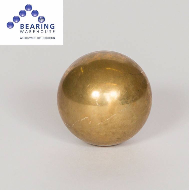
outlet pipe. In the end I settled on an 8mm diameter brass ball like this:
To retain the ball in position, I selected an M6 x 14mm
self-tapping stainless steel thread insert like this:
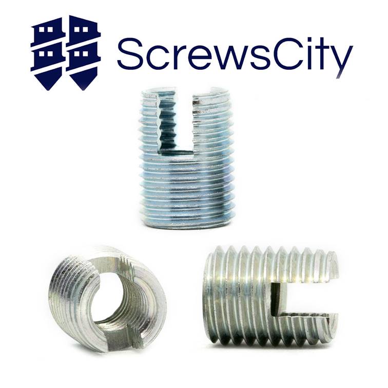
The thread insert is self-tapping in a 9mm hole in aluminium
and is easily driven in with a short M6 bolt. Once installed it is held very
securely in place. It is driven in slotted end first, which means that the
brass ball cannot seal against it preventing inward flow.
The diagram below shows the details of the modification:
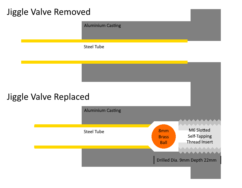
The 9mm hole needs to be accurately concentric with the original hold and the bore of the steel tube in order to guarantee a reasonably circular entry to the steel pipe and a good seal from the brass ball, although this was easy enough to achieve to the required accuracy by eye. It is drilled to a depth of 22mm to the shoulder of the drill bit; I did this by applying a bit of plastic tape to the drill but 22mm back from the start of the conical end and drilling to the depth of the tape. It isn’t critical. This allows the thread insert to be driven in flush and still allows a few millimetres of movement in the brass ball. The total depth of the aluminium at this point is greater than 40mm so the steel pipe is still very well supported. I finished the drilling by running the drill bit anticlockwise for a few seconds; this wasn’t removing significant metal but burnishing the entry to the steel pipe to a smooth seat.
Here is a picture of the finished replacement jiggle valve:
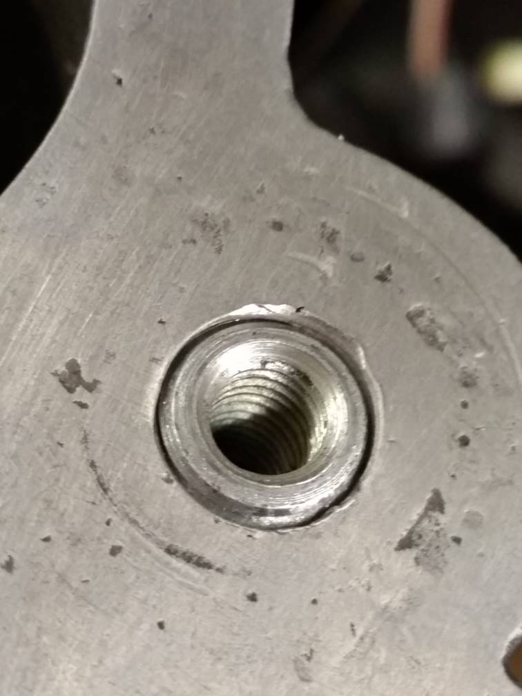
The self-tapping insert does tend to create quite a bit of
aluminium swarf in the valve which can jam the ball
or prevent it from sealing, so it’s important to make sure all of this is
cleared. I blew it out easily using a compressor.
I tested the finished jiggle valve by blowing and sucking
through both my valve and a couple of original valves at different rates; not
particularly scientific but I did find that the response of the original valve
was rather unpredictable, sometimes closing easily and sometimes sticking and
needing quite some flow to close. Overall the response of my valve was very
similar indeed to the original valve, a lot more predictable and fell well
within the range of behaviours of the original valves. With the valve held at
the angle at which it is installed in the car, you can blow gently outwards
without the valve closing, so air bubbles should escape easily. You cannot
however push any significant flow volume outwards without the ball closing off the flow. There won't be much coolant flow
allowed. The ball releases and the valve opens as soon
as you stop applying outward pressure. Flow in the inward direction is
relatively unrestricted.
I’m quite sure that my replacement valve should do a good
job of allowing air to bleed off without significant coolant flow. It’s got to
be a lot better than no valve at all or a simple restriction,
and makes previously unusable damaged inlet manifolds usable again.
I’ve made three of them so far and they all seem to work fine.