Fuel
Pump Diagnostics Using An Oscilloscope
Whilst trying to track down a fuel pressure issue on my 1.8K Series VVC,
I came across some interesting techniques you can use to diagnose the health of
a fuel injection pump in situ with an oscilloscope.
In order to avoid having to run the engine, I unplugged my inertia
switch and inserted a test wire with a male Econoseal terminal into the
terminal on the socket connected to the pump. You can easily
determine which pin is connected to the pump with a multimeter as it will
have a low resistance to ground when the switch is unplugged. I could then run
the pump without the engine simply by connecting the other end of the wire to
the battery +ve terminal.
I then hooked a DC current clamp around the test wire above. This gave
me a voltage readout proportion to the current being drawn by the motor, which
I connected to an oscilloscope. The following trace shows the current as the
pump starts up:
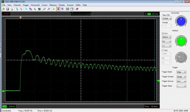
The first thing to note is that there is a large initial current surge.
This is considerably higher than the final current draw of the motor. If this
is considerably in excess of the nominal current draw of the motor given in the
manufacturer's specifications, you can be fairly sure that pump wiring is in
good order. In my case it was 8A and the pump was specified for 7.2A so I
couldn't really draw any conclusions.
The second thing to note is the current drawn by the motor is not
constant once it gets going but fluctuates regularly in a series of pulses.
These pulses are caused by the commutator in the motor rotating past the
brushes, with the current in each motor winding segment ramping up and down.
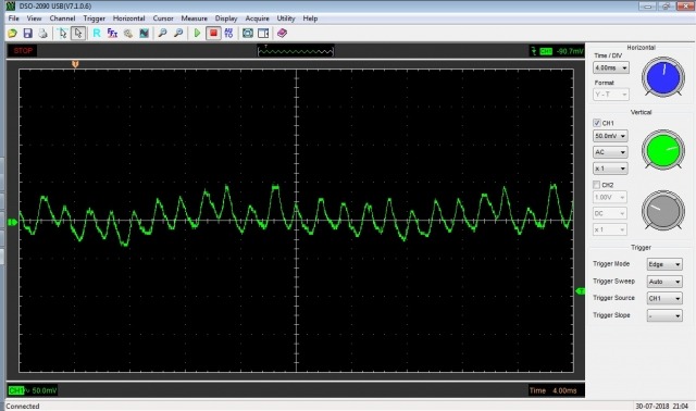
Below is a more detailed capture of these pulses (I switched to AC coupling to
eliminate the large background DC component).
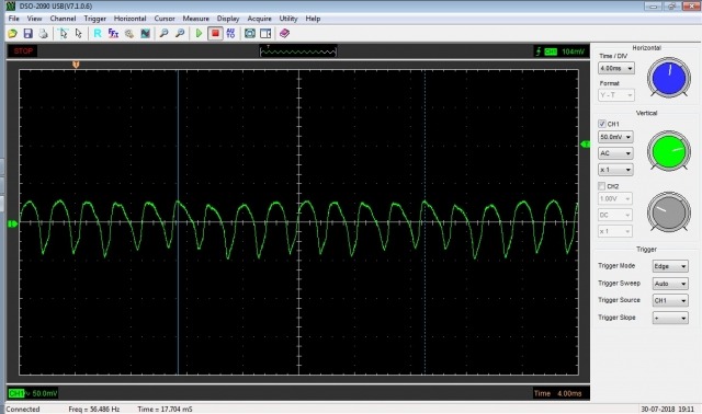
Looking the this we can see that all of the
pulses are roughly the same shape and size. If any were missing, we would know
we have an open circuit or burned out winding in the pump. If they vary wildly
in size and shape, this can indicate that the brushes and commutator are worn,
which is one of the main causes for a fuel pump become weaker as it ages. In my
case they were very even so my pump looked to be in good shape.
Looking carefully though, there are small variations between the pulses
and although these at first appear random, and interesting thing happens if you
take the image above and offset it by a certain number of pluses before
overlaying it on itself:
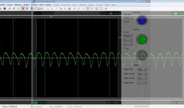
This is two copies of the above image overlaid on each other with
an offset of 8 pulses. You can that the waveforms now correspond again exactly.
The variations on the pulses are not random at all, but form a pattern that
repeats every 8 pulses. If you try this with any smaller number of pulses, they
don't align:
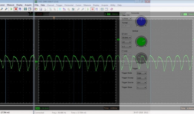
What this means is that each of the motor windings connected to each of
the commutator segments has a unique current signature, due to slight
manufacturing differences, patterns of windings, wear on the commutator etc.
The motor in this case must have an 8-segment commutator, so 8 pulses corresponds to a complete revolution of the motor. This
enables us to measure the overall time for 8 pulses (around 18ms) and then work
out the rotational speed of the pump (in this case 60000 / 18 = 3333rpm).
Sources on the internet seem to suggest that a current draw of around 7A
and a speed of around 7000rpm is normal, however this must vary a lot between
types of pump as my pump proved to be healthy (it would deliver 70psi when I
clamped off the return line and held a good regulated pressure under load - my
problem eventually turned out to be a faulty fuel pressure regulator). As with
all of these things, it is more important to look for changes over time and
differences between apparently identical components than focus on an absolute
number. I couldn't find any published data to compare all of this with for the
pump used on the Caterham, so hopefully my figures above can server as a
baseline for other people to compare to.
Out of interest, I repeated the exercise on my engine testbed which has
an externally mounted Bosch fuel pump and got the following results:
Average current draw was a lot higher (around 7A running), there was a
lot more variation across the commutator segments and the waveform showed the
same repeating pattern, but this time repeating every 12 pulses,
suggesting that the motor has a 12-segment commutator. Motor RPM worked
out about the same. Given that the above was a brand new pump when fitted
recently, I have even more grounds to declare that mine is very healthy.
Once we know how the motor current and RPM compare to typical values, we
can use these to identify some additional cases:
- High current draw, low RPM. Motor is working against a high
pressure. If the fuel pressure measured at the rail is high, there is
possibly a problem with the fuel pressure regulator or a blockage in the
return line to the tank. If not, the fuel filter possibly needs changing.
- Low current draw, low RPM. Motor is working against a low pressure
and is able to deliver a high flow easily. This would suggest significant
leaking in the fuel pressure regulator, or a regulator which opens at a
low pressure.