Wiring a Flick-Wipe
Switch
The following diagram is taken from an article on
the Lucas 2 Speed Wiper System at http://www.mgb-stuff.org.uk/wiper3.htm and adapted it to correspond exactly to the relevant
wiring in the Caterham installation,
so I've coloured the
wires appropriately and also added in the connectors provided to allow for the
installation of an intermittent wipe controller. These connectors also contain
one green/black wire for the windscreen washers so I've added it for
clarity even though it doesn't play any part in this. The diagram shows
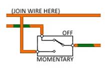
the wiper switch in the "Off" position and the wipers parked:
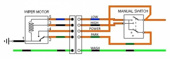
Notice how the parking system works. When the
wiper switch is in the "Off" position, the orange/green wire is
connected by the wiper switch to the orange/blue wire into the motor which is
the low speed motor supply. When the wipers are in the parked position the
parking switch within the motor connects the orange/green wire to ground,
shorting out the motor via the wiper switch and stopping it dead. When the
wipers are away from the parked position the parking switch within the motor
connects the orange/green wire to the orange wire which is the fused power
supply. This powers the low speed supply to the motor to keep them moving until
they reach the parked position.
To wire in a flick-wipe switch, we need to be able
to convince the motor that it is no longer parked. We can't just power up the
orange/blue wire to drive the motor as that is shorted to ground via the wiper
switch, the orange/green wire and the parking switch, so trying to power it
will just blow a fuse. We need to wire in a changeover switch the overrides the
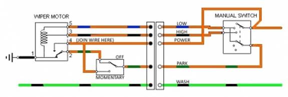
parking switch. One way of doing this is shown below:
Use a momentary switch with three terminals. It is important that
the switch is of the "break before make" variety, i.e. that as the
switch changes over the two outer terminals are not both connected at the same
time (in a "make before break" switch they will be and this will also
short the power supply and blow the fuse). I believe that the standard Caterham Flash Switch should be suitable (but I haven't test it) and this will
match the design of the other switches in the car.
To wire the flick-switch like this, cut the
orange/green wire and connect via the switch as shown, with the (usually
central) common terminal connected to the wiper switch side and the
normally closed terminal connected to the motor side. Then join another wire
onto the orange (fused supply) wire and take it to the normally closed terminal
of the switch.
When the flick-wipe switch is in its resting
position, the cut orange/green wire is reconnected and the circuit is exactly
as before. When the switch is operated, the motor is disconnected from the
short to earth through the park switch and temporarily powered from the orange
wire. Once the wipers start to move, the park switch changes over and the
flick-wipe switch can be released.
Wiring the flick-wipe switch above is convenient as
the various wires can connected close to the existing wiper switch, keeping the
wiring short and neat. However, some cars have an electronic intermittent wiper
controller box installed that activates intermittent wipe mode when the wiper
switch is briefly switched to slow speed and of again. Where installed, the
wiper controller is connected between the plug and socket shown in the
middle of the above diagram. The two connectors are unplugged from each other
and connected to the wiper controller. It detects the short pulse on the
orange/blue wire and will also therefore be triggered by the flick-wipe switch
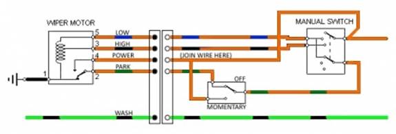
if wired as show above. I think the solution to this where an intermittent
wiper controller is installed is to make exactly the same wiring changes, but
on the motor side of the controller connectors as shown below:
Note that I haven't actually tested the above, but the wiper controller
unit doesn't make a connection to the orange/green wire on the switch side,
instead controlling the orange/blue wire directly. There will therefore be no
pulse seen by the controller on the orange/blue wire when the flick-wipe switch
is operated and I don't believe it will therefore be triggered into
intermittent wipe mode. However, whether it responds as expected to seeing the
motor coming off park would need to be tested. I think it will work OK. There
are actually two different intermittent wiper control units, the Lucas 6DA as
used on the classic Mini and various Triumph cars and a Caterham/Technisol unit
which works in the basically same way, but may or may not respond in the same
way to the changed wiring above.
The other alternative, if the flick-wipe switch is
to replace the existing intermittent wipe function, is to remove the two
connectors from the intermittent wipe controller and plug them together, taking
it out of the circuit. The first proposed wiring diagram could then be used.
One other potential problem with this could be that
as the flick-wipe switch returns to its resting position, the wiper motor is
very briefly disconnected. Most switches snap from one position to the other
very quickly and this would not be noticeable. If using a vintage Lucas type
switch, sometimes they do not snap quickly from one position to the others and
the wipers may stutter slightly as the switch is released. If this is seen as a
problem, the flick-wipe changeover switch shown in either of the above diagrams
could be replaced with a simple momentary switch and a relay as shown below:
Replace this (Switch Only):
With this (Switch & Relay):
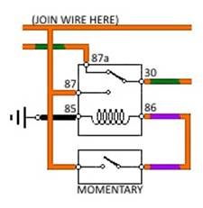
The contacts within the relay will always change
over very rapidly and any stuttering of the wiper motor as the flick-wipe
switch is released will be eliminated. This also has the added advantage
that a simple push button switch could be used, or a
two pin toggle switch as the switch itself does not need to provide changeover
functionality.
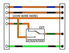
One final idea; there is a way of trying out any of
the above combinations without cutting any of the existing wiring. Holden
Classics sell complete sets of the 5-Way Harness
Connectors used for the intermittent wiper controller. If you made
up a small loom as shown below, you could simply plug this in line between the
existing connectors or on either side of the intermittent wiper controller if
installed and test before making any permanent changes to the car. The orange
wires could be neatly joined in this case by crimping both wires into on
terminal pin of one of the connectors. The connector shown with solid terminals
is the connector with solid male pins, the connector
shown with hollow terminals is the connector with hollow female sockets. The
position of each wire in the connector may be copied from the existing
connectors:
A similar loom could be made using the relay if required.
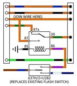
The loom shown below may be used to combine the
ideas above to make a plug in loom using a relay which allows the existing main
beam flash switch to perform a dual function; down to flash main beam, up to
flick the wipers. The existing flasher switch should be replaced with APEM 637H/2+U282 which has a MOM-OFF-MOM action. The existing brown/blue
wire should be connected to the central terminal, the existing blue/white to
the end terminal corresponding to the switch being pressed downwards and the
new orange/purple wire should be connected to the end terminal corresponding to
the switch being pressed upwards.