ECU
Modification Instructions – Rover MEMS 2J
A small number of modifications need to be made to the ECU in order to make it fully reprogrammable. These changes replace the standard ROM chip with an EEPROM which allows in-circuit programming and which has a suitable sector structure to allow erasure of the firmware and map whilst preserving a permanent boot loader. They also rewire one of the microcontroller pins in a way which allows the processor to switch the EEPROM between read-only and write-only modes for programming. This pin was designed to be used for the interrupt signal from an Intel 82527 CAN bus controller chip. I have never seen this chip present in a Rover MEMS 2J ECU.
ECU Compatibility Checks
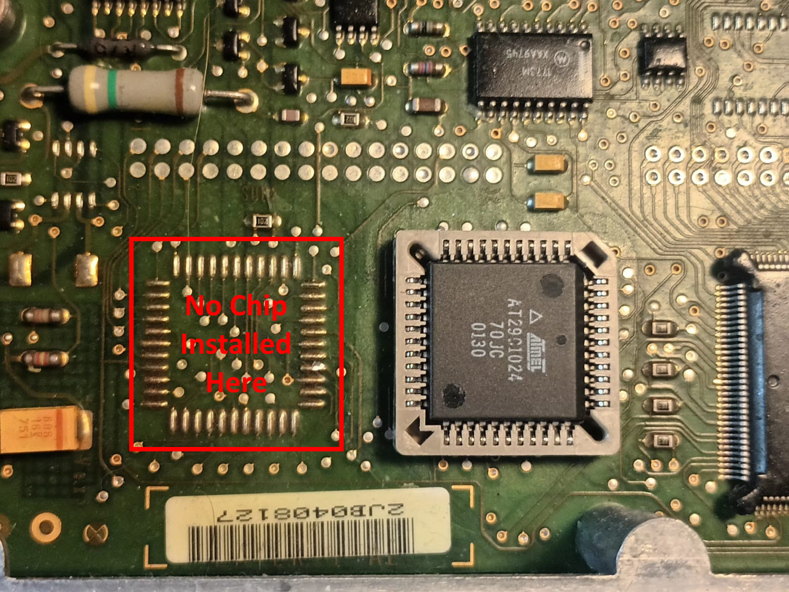
These modifications should be compatible with any Rover MEMS 2J ECU which does not have the Intel 82527 CAN bus controller chip installed. Ensure that the solder pads marked “No Chip Installed Here” are unoccupied as in the photograph below:
Backing Up the ECU
Before starting, use MEMS Mapper EU2 to read the ECU and save the file. This gives you a backup copy of the original firmware and map which can be written back to the ECU after modification.
ROM Chip Swap
Swap the ROM chip (the standard ROM chip is usually an AT27C1024) for an AT29C1024. NB: ONLY THIS SPECIFIC TYPE OF CHIP IS SUPPORTED. There are other type of programmable 1 Mbit PLCC44 EEPROM, but one of the others support 5V-only operation and have a suitable sector structure. The custom boot loader is written specifically for the AT29C1024 only. You’ll struggle to get them from mainstream suppliers here as they are obsolete from the manufacturer. But they are easily obtainable from Chinese obsolete silicon stockists on AliExpress. They have thousands in stock.
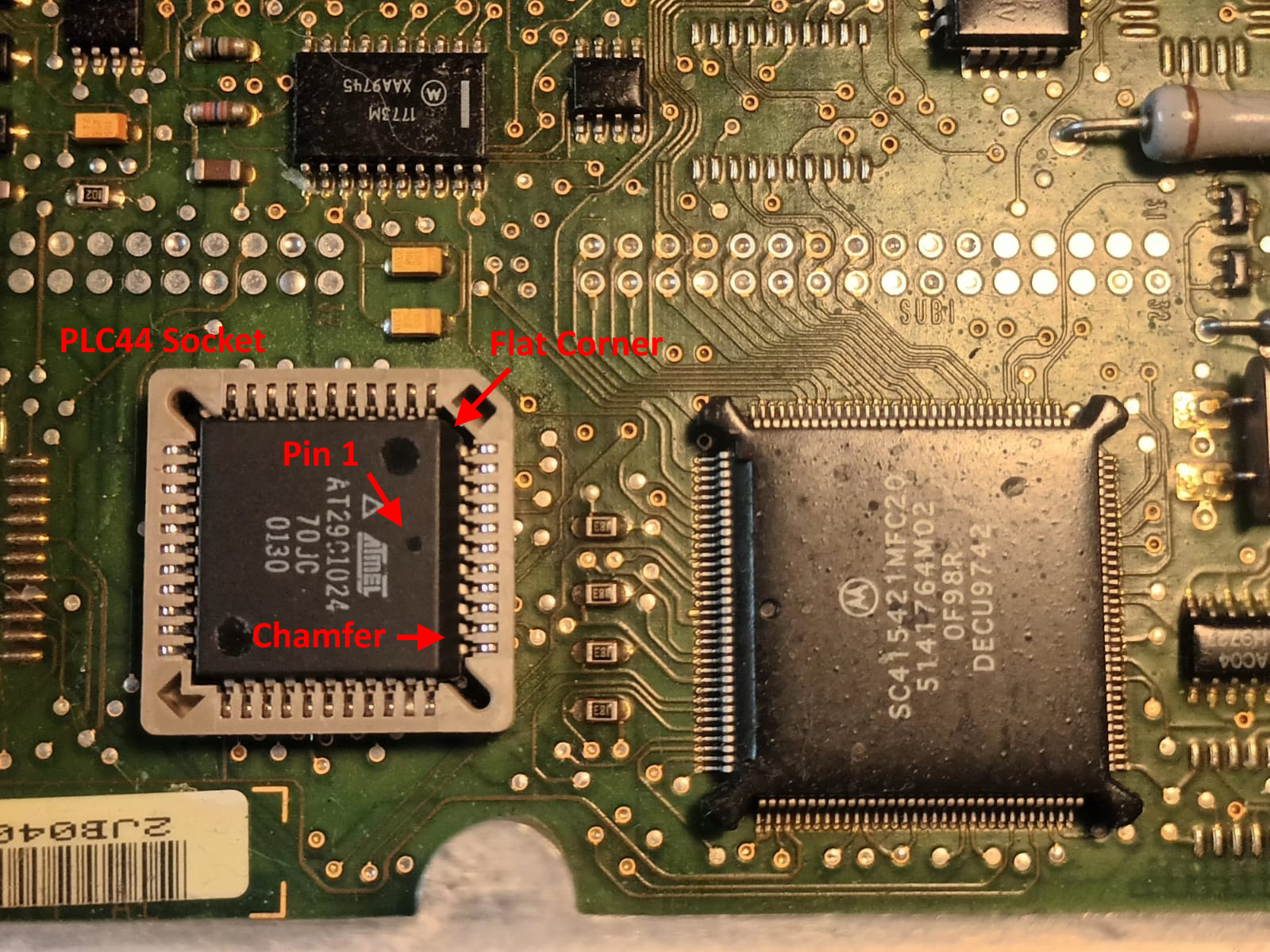
The chip is a PLCC44 package. It’s usually easiest to solder
a PLCC44 socket into the circuit board and then plug the chip in afterwards;
this certainly gives you more options e.g. if you find the chip wasn’t
programmed correctly. Make sure you put the chip in the right way around. Is
has one chamfered edge which should face towards the main processor. If you’re
soldering a socket in first, be careful as they look symmetrical but they have
one flat corner, this must be towards the processor chip on the side towards
the middle of the circuit board. Just make sure that the way the chip fits into
the socket will leave it with the chamfered edge towards the processor. You
can’t force the chip I the right way if the socket is the wrong way or the
socket will just crack and damaged the board, so make sure it’s right first
time. The picture below shows a socketed AT29C1024 EEPROM installed.
Note that the PCB is covered in conformal silicone coating. To solder the
socket successfully I usually strip the silicone around the area with Unibond
silicone remover (from a DIY store) then clean up with isopropyl alcohol on a
small stiff paintbrush. Sometimes you need to strip it once and clean up, then
desolder the chip, then strip it again and clean up to remove silicone that had
leached under the chip. You need to get rid of all traces of silicone to get
clean soldered joints when installing the socket. Be VERY careful not to damage
the PCB pads when removing the chip. Lifting a pad or tearing a PCB trace will
effectively render the ECU useless.
There are basically two ways to desolder the chip. In either case, you need to be EXTREMELEY careful not damage the PCB by lifting the chip using any force when there’s still a pin soldered down. If you pull a pad off the board, the ECU will be ruined. One method is to use a hot air rework station with a PLCC44 adapter. The other method is to use ultra-low melting point solder, such as the special ChipQuik alloy. If you work plenty of that into and around all of the pins with lots of ChipQuik tack flux, it’s possible to get all the pins hot enough just running a soldering iron around then to get the chip to come free with all of the joints melted at the same time. The difficult part is that the conformal silicone tens to leach underneath the chip and glue it to the board. It is then very hard to tell whether the chip still has a pin soldered down or whether it is simply stuck with silicone. With stuck with silicone, the chip will take some force to prise off the board. It critical to be absolutely sure that no pins are attached when doing so. The easiest way to do this is poke the chip with a tool to try to rotate a little bit in the plane of the board. Once the chip has some wiggle in this way, you know the pins are free you can then quickly lift it off. It does take a little bit of practice and judgement to get it right every time though.
If you’re not confident with the soldering jobs, I’m happy to help and modify an ECU for you.
I usually solder the sockets in with low melting point (138°C) solder paste and a hot air rework gun. It takes a bit of practice. I use a very thin layer of paste across the PCB pads to tack the socket down in the first pass, then add small amounts of paste to the hot board across the pins through the gaps in the socket using a syringe and a fine nozzle followed by hot air to melt the solder into the joints until I’m happy that everything is soldered correctly. I then check adjacent pairs of pins with a multimeter continuity tester just to make sure there are no solder bridges between pins. Some professional tuners knock the bottoms out of the sockets with a screwdriver and then solder with a fine soldering iron through the resulting large hole in the centre of the socket. I’m a bit wary of this; despite being assured that is reliable, it results in the chip sitting unusually low down in the socket. I have had one ECU on the bench where this resulted in poor connections.
Programming the Boot Loader
Before soldering or plugging the AT29C1024 chip in, you need to program it with the contents of the custom boot loader file “bmkcp004.boo”. This may be found in the “Executables\Boot Loaders\Rover K-Series\MEMS 2J” folder after unzipping a downloaded copy of MEMS Mapper EU2. This is the new boot loader I have written for the ECU which supports OBDII programming. Most cheap bench programmers won’t work with the AT29C1024 chip. One that will program it is the XGecu T56, also available on AliExpress. However, one word of warning: This programmer is often supplied with a PLCC44 chip adapter, but it’s a PLC44 to DIP40 adapter so 4 of the pins are not connected. It is designed for programming PIC microcontrollers and can’t be used for the 29C1024. You need to buy a separate PLCC44 to DIP44 adapter with all 44 pins connected.
Board Wiring Modifications
On the reverse side of the PCB you
need to make the following small changes:
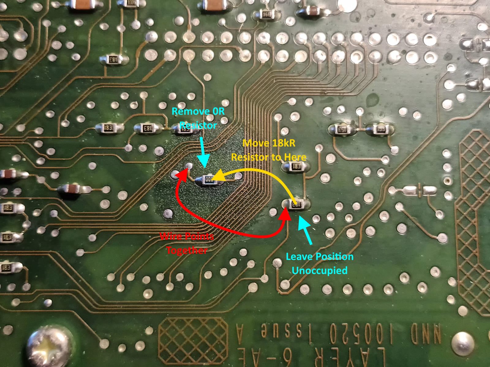
When finished it should look something like this:
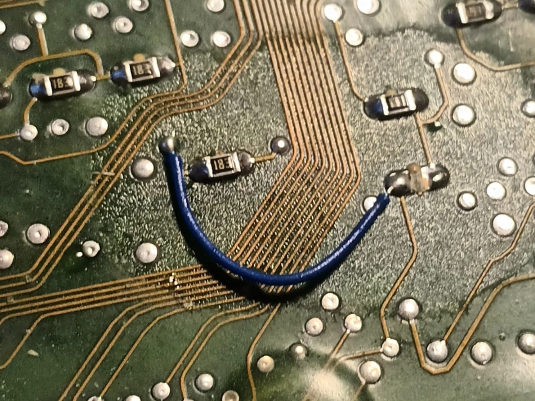
For anyone interested, here is an explanation of the wiring modifications described above:
Pin 74 of the 68332 microcontroller chip is designated as PF4/IRQ4’. It may be programmed as either an I/O port pin PF4, or as an interrupt input pin IRQ4’. The standard firmware programs this pin to be IRQ4’ and it is wired to pin 11 INT# on the 82527 CAN controller chip, with an 18kR pull-up resistor to +5V (the interrupt line is active low). However the 82527 is rarely if ever actually installed, so this line pin is effectively unused.
Pin 22 of the ROM chip is designated OE’. This pin needs to be pulled low to enable outputs and allow the ROM chip to be read. It needs to taken high to allow writing to the chip. This pin is normally tied to ground with a 0R resistor (effectively a removable jumper link), holding it permanently low and preventing a replacement AT29C1024 chip from being taken high and placed into write mode.
This 0R resistor is removed and discarded. It is replaced with the 18kR pull-up resistor taken from the IRQ4’ line which is not required without the CAN chip. This leaves the EEPROM chip in read-only mode, but allows it to be driven high by a logic output to put the EEPROM is write-only mode. The unused PF4/IRQ4’ pin is then reconfigured by the boot loader a PF4 and connected to the EEPROM OE’ pin allowing the microcontroller to switch the EEPROM between read and write modes.
When switched to write-only mode, the EEPROM is not readable and therefore program code stored within it cannot execute. All write operations within the boot loader therefore proceed by uploading a small routine into RAM and executing it from there; this routine switches the EEPROM into write mode, executes the write operations, then switches the EEPROM back into read mode before returning.
Case Lid Replacement
In my experience, by the time you’ve got the lid off the ECU
case, it will probably be too bent and damaged to sensibly seal it back on
again. I’ve had some laser-cut plate lids made up to the following design, and
they work well: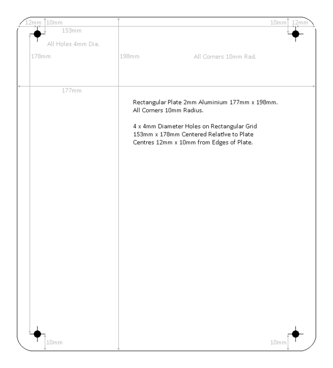
I try to keep a few of these lids in stock and can supply them if required. Liquid conformal silicone such as MG Chemicals 422C may be applied with a fine brush along the joint line and then externally along the joint to ensure a waterproof seal. The above design allows for a small overhang around the edge of the lids which makes it easier to run a bead of sealant around it. This same sealant is also good for the joint between the two case halves, and may also be applied to seal the board modifications and to mechanically support the small link wire used.
WARNING: Because the new lids do not wrap over the edges of the ECU, they are cut in thicker (2mm) aluminium for rigidity. The case screws therefore do not therefore engage as far into their threads as they do with the original lid. Do not overtighten them or you may strip the threads. Just tighten them enough to ensure the lid is secure.
If you’re not confident to make the ECU modifications yourself, or if you don’t want to have to buy the necessary equipment (ChipQuik alloy and paste, hot air rework station and PLCC44 nozzle, XGecu T56 programmer and PLCC44 to DIP44 adapter) and parts (PLC44 socket, AT29C1024, laser-cut lid, conformal sealant), I’m happy to help and modify an ECU for you. Since I seem to be getting quite a lot of requests now I need to charge something for doing this. Something like £75 including the PCB mods, installing the ROM socket, supplying and flashing the new boot loader ROM, supplying and fitting a new lid and sealing it all back up and bench testing. You only need to program the ROM chip on the bench ONCE, after that it’s all done over OBDII including boot loader upgrades etc. and buying all of the necessary kit for a one-off job is uneconomical.
Finishing Off
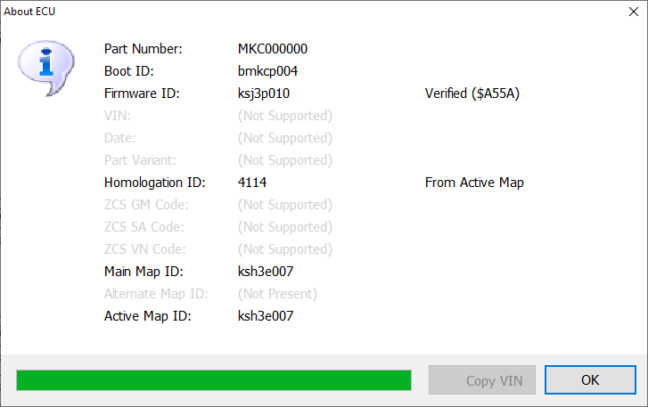
Once you’ve modified the ECU and installed an 29C1024 with the boot loader on it, you should be able to talk to the ECU using MEMS Mapper EU2. If you do About ECU it should report that it has boot loader bmkcp004, but no firmware or map installed. It will not be able run an engine in this state.
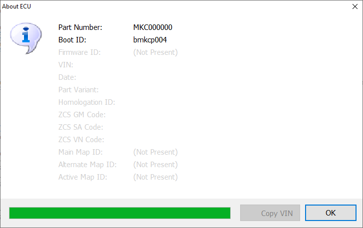
You then need to open the original file you backed up off the ECU using MEMS Mapper EU2 and write it to the ECU. This should proceed pretty much exactly as in the video I posted here https://youtu.be/IUIkVGuq-3w. At the end of writing to it, the ECU should report that it has boot loader bmkcp004 and the original firmware and map and engine management should be normal. You can them reprogram it over OBDII using MEMS Mapper EU2 as many times as you want.