Remapping the Rover MEMS3 ECU
Download
Link: https://andrewrevill.co.uk/Downloads/MEMS3Tools.zip
NOTE: THIS DOCUMENTATION IS UP TO DATE AS OF VERSION 5.11 RELEASE OF
THE MEMS3 TOOLS APPLICATION SUITE.
After a lot of work, here are the results
of my efforts to provide a workable remapping system for the MEMS3 ECU.
When I wrote this article: https://andrewrevill.co.uk/MEMS3Flasher.htm on “Reading/Writing/Flashing the Rover MEMS3 ECU” I said at the end that a full mapping application was in development. This is it.
I have continued to maintain the application since the
first public release, fixed a number of small bugs and added in quite a few new
features in response to feedback from users. In particular I’d like to thank
Troy and Alex at Northampton
Motorsport who allowed me to help out with mapping a Caterham on the
rolling road using my software and kindly took the time to give me feedback on
what additional features they would like to see to make it a truly useful
mapping tool, and to show me through those features in mapping suites for other
ECUs. This release now incorporates the changes which they suggested.
I present here a freely downloadable and
shareable tool which allows the ECU to be remapped and enough information about
the table and scalar data structures to allow the following features to be
effectively reprogrammed:
- Fuelling
- Air Flow
Model & Adjustments ®
- Target AFR
(Air Fuel Ratio)
- Base Scale
Factor
- Warm-Up
Enrichment
- Acceleration
Enrichment
- By
Temperature & RPM ®
- By TPS
(Throttle) Range
- Injection
Timing
- Injector Dead
Time & Voltage Compensation ®
- Injector Flow
Rate & Voltage Compensation ®
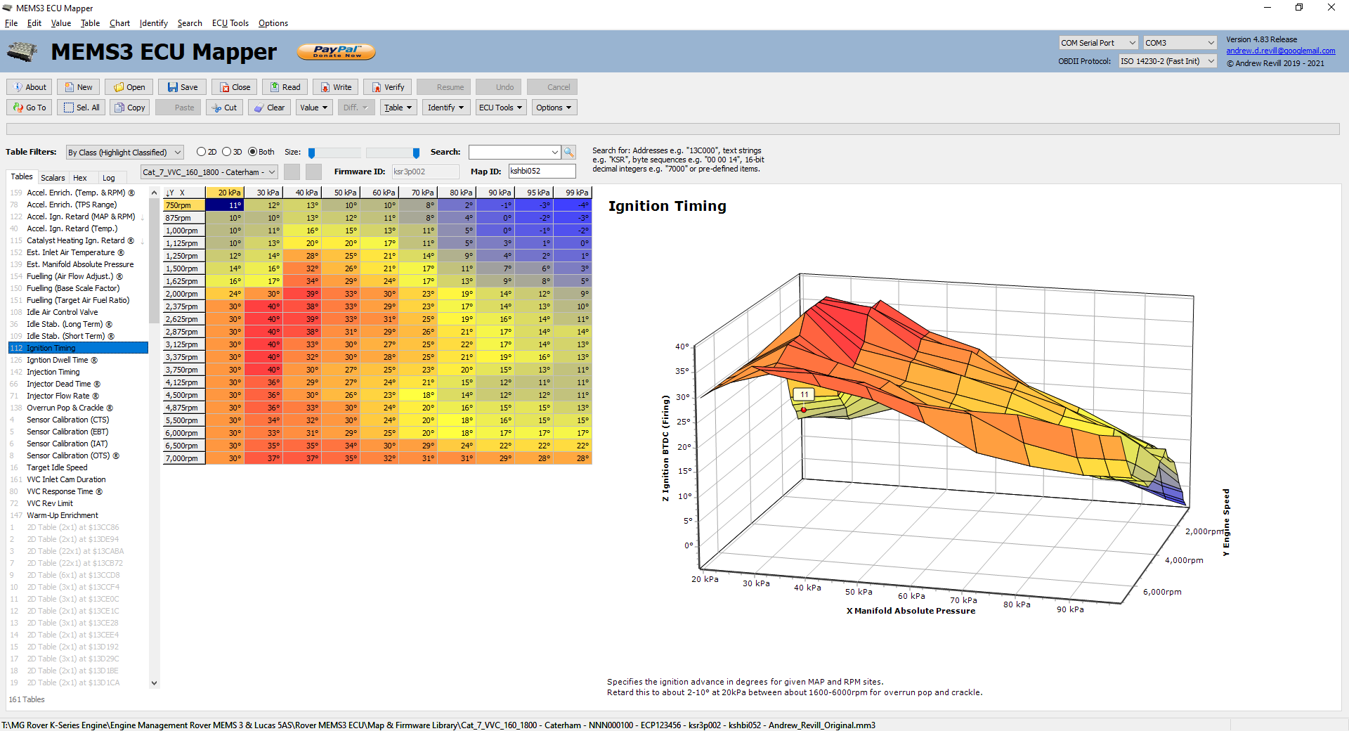
- Ignition
- Ignition
Timing
- Ignition
Dwell Time ®
- Acceleration
Retard
- By MAP &
RPM
- By Coolant
Temperature
- Catalyst
Heating Retard ®
- Idle
Air Control Valve
- Idle
Stabilisation
- Long Term
Using Idle Air Control Valve ®
- Short Term
Using Ignition Timing
- Overrun
Pop & Crackle Effects ®
- Target
Idle Speed
- Sensor
Calibration Curves
- CTS (Coolant
Temperature Sensor)
- OTS (Oil
Temperature Sensor) ®
- IAT (Inlet
Air Temperature Sensor)
- EBT (Engine
Bay Temperature Sensor)
- Unused Pin 47
®
- Sensor
Estimates
- Inlet Air
Temperature
- Manifold
Absolute Pressure
- Variable
Valve Control (VVC) Engines
- Inlet Cam
Duration
- Response Time
®
- Rev Limit
- MPI
(Non-VVC) Engines
- Rev Limit
- Immobiliser
Delete
- Radiator
Fan Control
- Fan On
Temperature
- Fan Off
Temperature
Throughout all of this, please bear in
mind that I've had no documentation or help on this from MG Rover, anyone
previously associated with MG Rover or any of the well-known remappers. So what
I present here is my own "working model" of the ECU, determined
through inspection and experiment; MG Rover may well have defined things in
completely different terms. I have formed a working model of my own which is
sufficient to allow these features to be reprogrammed but which may not be
aligned exactly with the way the ECU was originally designed and described. My
model of the ECU may continue to evolve and develop as I gain more
understanding.
The tool was developed initially as a
research tool for me, and has been slowly evolved into a mapping tool that I
can release publicly. When I set out on the adventure of developing all of this
I had a lot less knowledge of the workings of the ECU, and the tool has evolved
in parallel with my understanding. Because of this, some things may have been
done differently if I knew at the start what I know now; but I think I’ve made
a pretty decent job of keeping it clean, tidy, well-structured and fairly
intuitive.
Note that throughout the definitions of tables
and other values in the tool, some are marked with an “®” symbol. These denote “Research” and indicate that there are still
some details which need to be tied down or validated. My descriptions of these
items may not be entirely accurate yet in these cases.
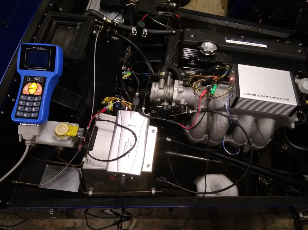
My car has spent many winter months
hooked up to breakout cable bundles, programmers, signal generators,
oscilloscopes and at times two different laptops, one running my mapping
application and the other listening and monitoring through other cables.
License & Warranty
As for my MEMS3 Flasher tool I’ve decided
to release the executable into the public domain. Feel free to copy it, share
it use, distribute it, give it to your mates, do what
you want with it. I just want it out there as a tool that people can use if
they need it; the more we can spread the knowledge about these units around the
K Series community the better as far as I’m concerned. I think it’s pretty
robust but it’s probably not perfect, feel free to let me know if you find
anything wrong, there’s an email link in the top right hand corner. I’ll try to
fix things that get found and keep it maintained but I’m not offering any kind
of warranty or guaranteed service level though. This has been and will always
be a side project for me.
![]()
Unlike with the MEMS3 Flasher tool, I’ve
decided to add a PayPal Donate button at the top of the screen. It’s taken me
over a year of my spare time to get to this stage. If you manage to get some
value out of it and feel like showing your appreciation I’d be most grateful,
but there’s no element of compulsion, the tool is free to use without
restriction for as long as you want to use it.
Fail Safe Read & Write
Before diving into the details, I would
just like to say that since releasing the previous MEMS3 Flasher tool I’ve put
a lot of work into fail-safety. I voiced some concerns over possible risks of
“bricking” an ECU if a write failed when I wrote up that tool. Since then, I’m
pretty sure I’ve come up with a fail-safe write procedure which on paper and in
practice should not run the risk of leaving the ECU in a “bricked” condition
(provided that the map and firmware you are writing to it are valid and
sensible - the ECU is not particularly fault-tolerant when it comes to
corrupted maps etc.). Although I wouldn’t recommend it, you can now interrupt
any process at any point and the ECU will be left in a condition where it will
still boot up safely ready for you to repeat the operation. I have repeatedly
tried to “brick” an ECU with the latest code by doing all of the following many
times, at many different points in the process, both during full firmware write
and map updates, without any problems:
- Turning off the ignition.
- Pulling out the ECU connectors.
- Pulling out the OBDII connector.
- Pulling the USB cable out of the
back of my laptop.
- Killing the mapping application
through Task Manager.
- Rebooting my laptop.
With the latest code, none of these have
been able to induce any serious issues at all. In the worst case (in fact in
pretty much every case) you just need to turn the ignition off and on again to
reset the ECU, then make sure everything is connected up again and repeat the
write operation. The ECU will be left in a state where it won’t run the engine
(until you repeat the write operation) but it will drop back into its boot
loader code and communicate with the mapping application, waiting for
programming instructions.
I have updated the latest release of the
simpler MEMS3 Flasher tool to use the same underlying code so that is now also
fail-safe.
The research required to get this write
cost me many “bricked” ECUs along the way, but I had modified a couple of ECUs
with sockets for the EEPROM chips allowing me to remove them and recover them
in a stand-alone programmer each time. I am now confident enough in the code
that I have reversed all the modifications on my ECUs and put them back to
standard with permanently soldered EEPROM chips. I do not anticipate “bricking”
any more ECUs - and if I didn’t have the self-belief and confidence to use it
on standard ECUs then how could I expect others to?
I have come across a single case where
somebody using my software managed to brick an ECU. They subsequently sent me a
copy of the file they were trying to write to it at the time, and I was able to
determine that it was damaged. It appeared to be incomplete, as though a large
part at the end of the firmware had not been read from the ECU. I’m not sure
how the file became damaged, but I suspect that somehow the user cancelled the
read before it was complete.
In version 4.80 I have therefore added
further protection against the possibility of a corrupted read from the ECU or
a damaged disk file leading to invalid firmware or map being written back,
potentially bricking the ECU. The last byte of a genuine firmware, coding or
map block will always contain $FF (no real firmware filled its allocated block,
no real firmware placed the table index right at the end of the map and an ECU
would need to be coded to hundreds of different vehicles before the coding area
became full). The application now sets the last byte of each block to $00 to
mark it as invalid before beginning a read. If the read fails to complete
(either through being cancelled by the user or through an error), the block
will then remain marked as invalid. If the read completes but the block
checksum is found to be incorrect, the block is again invalidated immediately
by setting the last byte to $00. Blocks marked as invalid cannot be written
back to the ECU. Because the valid flags are placed within the data, they are
saved to files with the firmware or map respectively. If a block is read and is
found to have an invalid checksum but is then saved to disk (at which point the
checksum will be corrected in order to allow disk file corruption to be
detected), next time the file is opened the checksum will be correct but the
block will still be marked as invalid as the last byte will contain $00 and so
the application will still not allow the block to be written to the ECU.
An invalid map which could brick and ECU
can potentially be created in one of several ways:
- The
map present in an ECU could possibly be corrupted. This is however very
unlikely due to multiple layers of checking when the map is written and
the fact that the ECU must be operating normally in order to allow the map
to be read.
- A
communications error may lead to the map being corrupted on read. This is
very unlikely as each message block contains a 1-byte checksum, meaning
that there is only a 1 in 256 chance of a corrupted message block going
undetected during a read. The overall map is then checked by the
application with a 2-byte checksum on read, meaning that there is only a
further 1 in 65536 chance of a corrupted map going undetected. A map which
is found to be corrupted cannot be written to the ECU.
- The
user could cancel the read of the ECU or it may fail with an error before
has read the whole map. In this case the last byte will be left containing
$00, the block will be marked as invalid and
could not be written back to the ECU.
- A disk
file containing a map may become corrupted in storage or transit. Although
this is possible, it is very unlikely that such a corrupted map could be
written back to an ECU because the application checks the map with a
2-byte checksum on load, meaning that there is only a 1 in 65536 chance of
a corrupted map going undetected. A map which is found to be corrupted
cannot be written to the ECU.
- The map
table editor features in the application may produce a map which the ECU
cannot accept. In extensive testing of the final releases of the
application I have NEVER seen this happen. I now have quite a number of
users who use the application regularly and nobody has EVER reported an
error where the application itself corrupts a map.
- The
user can edit the map or firmware in raw hexadecimal format. If you edit
the map or firmware in raw hexadecimal format there is no way for the
application to prevent you from creating something which may damage the
ECU, so USE THIS FEATURE WITH GREAT
CAUTION AND ONLY ATTEMPT TO WRITE BACK A MAP WHICH YOU HAVE EDITED IN THIS
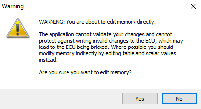
WAY IF YOU REALLY UNDERSTAND WHAT YOU ARE DOING! As of version 4.85,
the first time you attempt to edit a map or firmware in raw hexadecimal
format within a session you will be given a warning as shown below. You
need to click Yes in order to allow raw
hexadecimal editing. By default the No button is highlighted.
I’m fairly confident that with these
latest changes, the one single case that I know of where an ECU was damaged
could not have occurred. The corrupted file would have been detected and the
application would not have allowed it to be written back to the ECU.
AS OF VERSION 4.87 THERE IS A NEW FUNCTION ON THE ECU TOOLS MENU TO
RECOVER A BRICKED ECU. This should allow
full and easy recovery of an ECU that has been bricked by any of the methods
above (or in any other way, including using other programming tools, no matter
how badly the firmware and map have become damaged). See the sections on ECU Tools and Recover Bricked ECU below for more
information.
In summary then:
- Reading an ECU should be COMPLETELY safe. You can go ahead and look at your maps
without any risk.
- Writing an ECU, as far as I can determine, should
now be comprehensively fail-safe
and very low risk indeed.
- Even if you do brick an ECU, there
is a simple recovery option available.
I will now use this many times on my own
car whilst looking for more features without a second thought.
Vehicle Families
This application was originally developed
to support Rover MEMS3 ECUs on petrol K-Series engined Caterham vehicles with a
Lucas 5AS immobiliser. It is now used on other petrol engine vehicles across
the MG Rover range, including those with Lucas 10AS, Pektron and BMW EWS 3.D
immobiliser systems and on the closely related Land Rover Discovery Td5 diesel
engine ECU. Whilst most of the features of the application are applicable
across the whole range, some of the ECU Tools only work on some of these ECUs
and some of them are actually dangerous to use on other ECUs as the same
commands perform completely different functions. In particular the “Clear Adaptations”
features are not applicable to Disco Td5 diesel ECUs and the “Learn Immobiliser
Code” feature MUST NOT BE USED WITH THE
BMW EWS 3.D SYSTEM as it will lead to permanent synchronisation loss with
the rolling code system (these immobilisers are much more secure and can only
be reprogrammed with dealer systems).
Before starting to use the tool, please
select the correct vehicle family from the combo box at the top of the window.
This will hide or disable those features which are not applicable for safety:
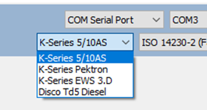
The vehicle families supported are:
- K-Series 5/10AS – This is the default, the most commonly
used and covers all vehicles with K Series petrol engines and Lucas 5AS or
Lucas 10AS (some Land Rover models) immobilisers. It covers all Caterham
installations.
- K-Series Pektron – This covers all MG Rover vehicles with
K-Series petrol engines and Pektron immobilisers (used on later model
years only).
- K-Series EWS 3.D – This covers all Land Rover Freelander
vehicles with K Series petrol engines and the BMW EWS 3.D immobiliser
system.
- Disco Td5 Diesel – This covers all Land Rover Discovery
vehicles with Td5 diesel engines.
Current feature restrictions are:
- Clear Fuel Adaptations – This is only allowed on K-Series petrol
engines.
- Clear Flywheel Adaptations – This is only allows on K-Series petrol
engines.
- Learn Immobiliser Code – This is only allowed with Lucas 5/10AS
and Pektron immobilisers.
ECU Tables, Indexes, Scalars &
Versions
Configurable data inside the ECU appears
in two different forms. Tabular data is stored in a well-defined table format.
There is a lot more information on 2D and 3D tables below. What I have referred
to as “Scalar Data” is in the form of single number values, rather than tables.
Many of the numbers and values used in calculations inside the ECU are
available in the map file and can be edited. This includes things like ECU fan
control temperatures and rev limits for non-VVC ECUs, but also flags for
immobiliser deletes etc.
The mapping program is written in a very
generic way; there is no hard-coding of special handling for particular
features. The program itself understands nothing of ignition timing or target
air fuel ratios for example. All of these are defined through configurations
which the user is able to modify and extend. In this way I was able to write
the application before I had a good understanding of the ECU and use it as a
research tool. If also means that as I or others discover new features they are
easily configured in the map editor without the need to change code. Apart from
those described here, there are many other tables and scalars in the ECU, all
of which are accessible through the tool. There is however very little information
on what table or scalar value does what, so I've concentrated on identifying
the tables and scalars that control identifiable features and those which would
be needed in order to adjust the mapping of an ECU to suit a modified engine.
There are no keys or axis labels for the tables inside the ECU, all you get is
a table of numbers, so I’ve had to work out what they do by changing them and
looking for the effects; or conversely, identifying an effect and then tracking
down the control data in the ECU, often by a careful process of elimination and
a lot of head-scratching, searching for patterns in what I see etc. The scalar
numbers are even harder to identify as all you get is one number. For example
the number 7000 appears many times in the scalar data, one of them is the rev
limit and the others are not. I will continue to search for further
identifiable tables and features.
There is considerable variation between
the table and scalar structures in different ECUs. The VVC ECU differs from the
MPI ECU and each of these ran a number of different firmware versions. The
tables in the ECUs are not identified by names or fixed identifiers as far as I
can see. Towards the end of the map memory there is an index, which contains
the memory locations of each of the actual tables. The ECU appears to identify
the tables purely by their position in the index, so I have used this as the
identifier for each table in my application. So for a given firmware version,
across multiple different maps, for example the table at index position 10 will
always have the same function. It may appear at different addresses depending
on the sizes of the other tables in the map, but it will always be pointed to
by the same index position. Across different firmware versions, the table with the
same function may appear at a different index, however they are broadly
consistent; there is trend towards tables appearing at slightly later positions
in the index in later ECU versions, particularly the higher indexed tables, as
tables appear to have been inserted into the sequence to support new features.
A similar pattern emerges in the scalar
data. The address at which a particular value appears will vary between
different firmware versions, but will always be consistent between different
maps for the same firmware version. There is no index to the scalar values; no
index is needed as they are all of a fixed size, so always appear in the same
location. So I have used the memory address as the identifier for each scalar
in my application.
So tables have identifiers like 1, 2 …
(up to around) 163 and scalars have identifiers like $13C014, $13C016 etc.
As I will describe below, in most cases
you won’t need to worry about all of this detail. Because it varies so much
between different ECUs, I’ve built in a machine learning ability in my
application. In most cases, it will be able to use its knowledge of other ECUs
that it has seen to correctly identify both the tables and scalars in any new
ECU it comes across; and if you do have to make any changes, or if you identify
any new features in one ECU, it should use these to improve its algorithms to
allow it to correctly apply these changes and find these new features in ECUs
it sees in the future.
So hopefully, when you hook this up to
your ECU, if it has seen the firmware version before it will know where
everything is and everything will show up with sensible names and configured
correctly, and if it hasn’t seen the firmware version before it will offer to
identify all of the tables and scalars automatically and should find them all,
or at least most of them, correctly.
If you do want to go hunting for table or
scalar values yourself, I’ve discovered a few “rules” that may help along the
way:
- The
ECU was designed by “Sensible Engineers”. It is well thought out. Things
are generally stored in an intuitive way which relates directly to the
feature they describe.
- Everything
seems to be done in 16-bit Integer maths. So there are no floating point
numbers, no fractions. Table data always seems to be signed 16-bit, so
whole numbers between -32,768 and +32,767. Scalar data may either be
signed or unsigned, in which case it will be whole numbers in the range 0
to 65,535. Scalar data may also be bit flags, so each 1 or 0 in the number
written out in binary is a switch that turns something on or off.
- This
means that to get a decent level of precision, things are often scaled by
a power of ten to use the full range. So for example percentage multiplier
in the range of 0 to 100 may be stored as 0 to 10,000 (representing 0.00
to 100.00) as this gives an effective 2 decimal place precision. They
couldn’t go higher to 100,000 as that exceeds the 16-bit Integer range.
They could have used 0 to 65535 to represent 0 to 100% but this would have
led to unintuitive units (for example 30% would be 19961). So when looking
at numbers inside the ECU, remember that the decimal point may not be at
the end.
- Units
used are generally sensible and intuitive. They are also consistent. So
for example engine speeds are always in whole number RPM,
never is radians per second or anything else. Temperatures are always in
degrees Kelvin (multiplied by 10 to give 1 decimal place precision as
above). But even low-range temperatures like inlet air temperature are
never multiplied by 100 or 1000, even if these would still fit in the
16-bit integer size; this is because there are some temperatures in there
that look like combustion or exhaust gas temperatures which go a lot
higher, and the rule that temperatures are always stored in the same way
seems to take precedence.
- Data
items used by the same piece of program code are generally kept together.
This is particularly true of the scalar data. This gives you a clue where
to look (for example once you have found the Fan On temperature, the Fan
Off temperature is right next to it). This also means that as the ECU
evolved over the years and new tables and scalars were added, they were
generally inserted into the sequence at the logical position rather than
added at the end. So over time, the position of a given scalar tends to
move to higher memory addresses, and more so for the ones towards the end
of the list, as others get inserted ahead of them.
- Most
tables usually contain positive numbers (or mixed positive and negative
numbers). There are only a few tables which contain only negative numbers.
These are generally low-resolution tables, and with only one exception are all grouped together in a contiguous block in the
ECU. Two of these tables I have identified as being associated with a
performance-reducing ignition retard effect which can be mapped out to
sharpen up the response of the car. I suspect that they are all possible
associated with similar detuning effects and they may well be worth
further investigation. The negatives all clustered together stand out like
a sore thumb as though the designers were trying to tell us something.
Just for information, I have displayed a small down arrow next to any
table which contains only zeroes and negative values.
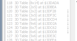
Table and Scalar Classes
In order to make sense of the above, I've
defined the idea of table and scalar classes. The idea is that you can set up a
number if classes which remain fixed across all ECUs, and then for each
individual firmware version you just need to link table indices and scalar
addresses to classes. So for example I have defined an Idle Air Control Valve class. For the ECU in my car, class Idle Air Control Valve is assigned the
table at table index position 108 (for brevity I will just refer to Table 108
etc. in the future). The table class defines the description used for the
table, any comments, and the properties of the X, Y and Z axes.
Since a lot of tables will for example be
indexed on MAP, I've defined axes through classes in the same way. So there is
a Manifold Absolute Pressure axis
class, and the Idle Air Control Valve
table class assigns the Manifold
Absolute Pressure axis class to the Y axis. The axis class defines the axis
name. It defines the column width required and the prefix, suffix and decimals
for display purposes and it also defines a scale and offset used to convert the
numbers in the table into meaningful numbers for display. For example the Inlet Air Temperature axis class has a
name of “Inlet Air Temperature”, a suffix of "°C", a scale of 0.1 and
an offset of -273.2. This is because temperatures are stored internally in
tenths of a degree Kelvin and I wanted to display them as degrees
Celsius/Centigrade. So a table value of 2932 is multiplied by 0.1 to give 293.2
and then offset by -273.2 to give 20 - it represents 20°C. Formatting the axes
in this way makes the tables a lot more readable. 20°C is a lot more meaningful
than 2932.
Note that as described in more detail
below, the actual body of a table is defined as an axis (always the Z axis -
think of it being displayed in a chart with one or two “input” axes and a data
axis). So for example the Base Ignition
Timing table has an X axis with MAP values, a Y axis with RPM values and a
Z axis with ignition timing values. In this way the scaling and display
properties for the ignition timing numbers are handled in exactly the same way
as the MAP and RPM numbers - by defining the properties of the Z axis.
All of the scaling applied to axes and
table values works both ways, so for example where a temperature axis has been
scaled to read in °C as above, you can edit or paste value in °C and they will
automatically be scaled backwards to write the correct values into the
underlying table. So you can treat the table as though it actually contains the
scaled values and just forget about the scaling once it is set up.
Scalar classes also allow a single axis
class to be specified. This describes the way in which the values are scaled
and offset in exactly the same way as for table values. The axis class
definitions are common to both tables and scalars as, for example, there are
both tables and scalars which specify Coolant
Temperature values.
All of the classes I have set up are just
examples. You can use mine, or if you want to dig deeper into the ECU using the
tool and manage to identify the meanings of some more tables, you are free to
define your own classes. If you do so, please share so that I can update the
definitions in copies that I distribute.
Dimensions and Axes
The tables found in an ECU are
traditionally described as 2D or 3D.
Mathematically a 2D table is actually a 1
dimensional array of numbers, but you can imagine it being displayed as a 2D
chart. When looking up a value in a 2D table there is only
one input variable, the second "dimension" being the output variable.
For example here is a 2D table:

Mathematically a 3D
table is actually a 2 dimensional array of numbers, but you can imagine it
being displayed as a 3D chart. When looking up a value in a
3D table there are two input variables, the third "dimension" being
the output variable. For example here is a 3D table:
When the ECU wants
to look up a value in the table, if a cell exists for the axes values required,
the number in that cell is used. If (as will be more usual) the axis values
fall between cells, the ECU will interpolate between the cells on either side
to calculate an intermediate value. When the axis values lie beyond one end of
an axis, I have seen evidence that in some cases the ECU just uses the closest
edge value and in others it actually extrapolates from the two closest values.
In my application,
tables have X, Y and Z axes. In a 2D table, either the X or Y
will have just one position and there is no "value" associated
with this position. In every case I've seen in MEMS3, 2D tables will have
multiple values on the X axis and the Y axis is unused, but if a table is found
that has multiple values on the Y axis and the X axis is unused, my application
will cope with it correctly as a 2D table of the other orientation. 3D tables
have multiple values on both the X and Y axes. In both cases, the Z axis
describes the output value being looked up in the table. So in the examples
given above, the 2D table has X axis with sensor voltages, no Y axis and a Z
value giving the corresponding temperature. The 3D table has an X axis values
with MAP values, a Y axis with RPM values and Z axis with air flow numbers.
In order to
maximise the amount of data that can be displayed, tables in the application
are always displayed with the longer axis of X and Y (i.e. the one with most
defined values) going down by default. So sometimes a table will have the X
axis across and the Y axis down and sometimes it will have the X axis down and
the Y axis across. The top left hand cell in the display shows you the
orientation, although once you have classified a table it doesn't really matter
as the designations "X" and "Y" only really relate to the
order in which the values are stored in memory - as a user you will work in
terms of the MAP axis and the RPM axis. For ease of data visualisation, the
application does allow you to transpose the orientations of the X and Y on the
table and chart, and also allows you to invert (reverse the direction of) the
axes on the chart individually. By default the depth axis of the chat is
inverted (numbers increasing from the back towards the front) as this gives a
layout of points in the chart which most closely corresponds to the layout of
the numbers in the table.
Classifying Tables and Scalars
All of this means that for a firmware
version not previously seen, it will be necessary to identify and assign the
appropriate classes to the relevant tables and scalars. In order to make this
easier, I have shown below examples of how these tables and scalars appear and
their indices in various different firmware versions. In addition I have added
a learning capability to the application; it is largely capable of identifying
the tables automatically based on similarities with other tables seen before
for other firmware versions.
I have "seeded" the application
with a selection of firmware versions, in the hope that it should be able to
find most of the tables in most other versions that I haven't seen
automatically. What it all comes down to is selecting the appropriate class for
each table of interest. I'll talk about how you do this further below.
That's enough theory for now, let's get into the application itself where it will all
make a lot more sense...
MEMS3 Mapper Application
You can download the full suite of MEMS3
Tools as a ZIP file here: https://andrewrevill.co.uk/Downloads/MEMS3Tools.zip.
You need to download the ZIP file and unzip all files into a single folder.
This includes the simpler MEMS3 Flasher application which is described here: https://andrewrevill.co.uk/MEMS3Flasher.htm. It also includes the MEMS3 Terminal and modified FTDI DLLs that I
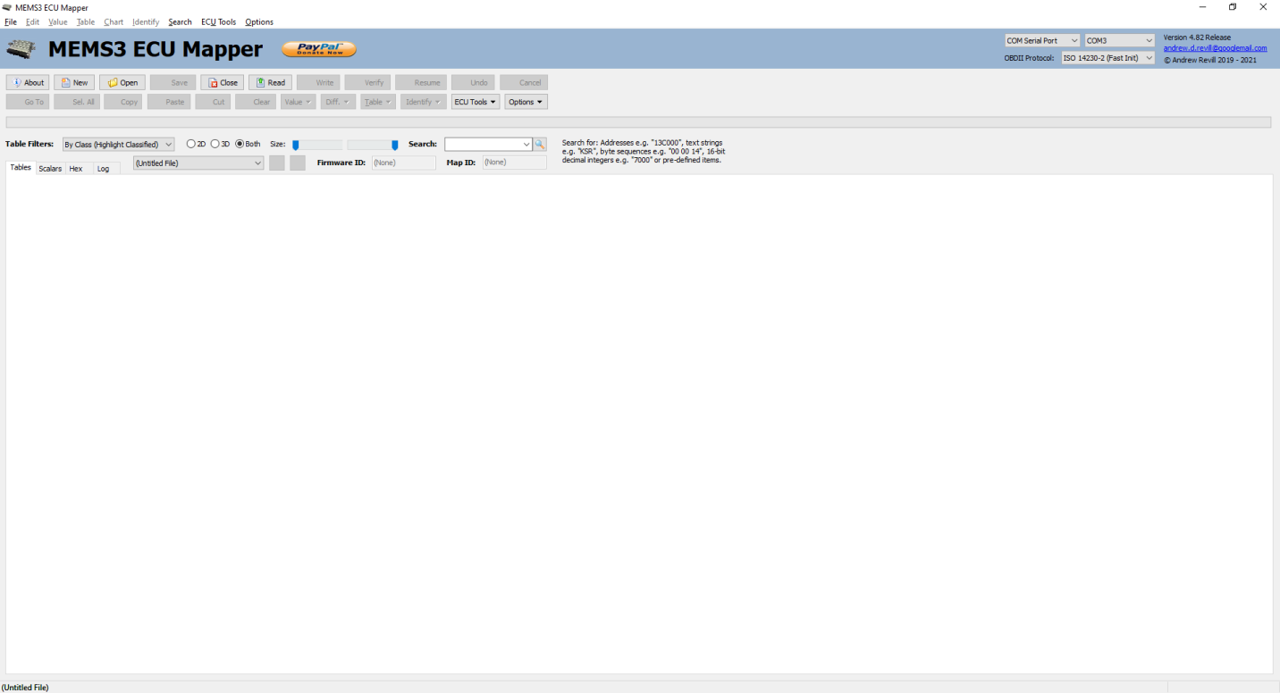
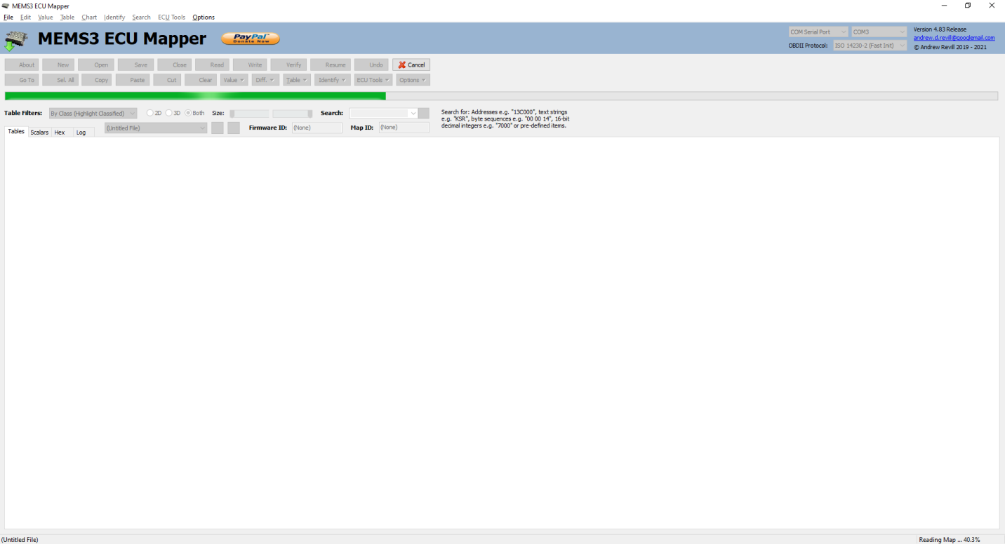
talked about in the earlier write-up. To run the application, double click the "MEMS3Mapper.32.exe" file (32-Bit
Windows version) or “MEMS3Mapper.64.exe”
file (64-Bit Windows version) as appropriate for your operating system. You
should see a window similar to those below. The application may appear slightly
differently on different versions of Windows, but it should work in the same
way. Here it is on Windows 10:
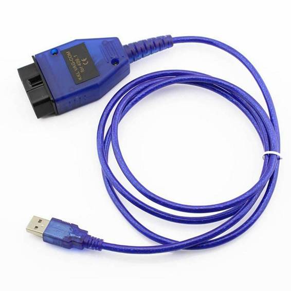
Hardware requirements are similar to those I described for the MEMS3 Flasher tool. I have however since rewritten the low level interface to the ECU to remove all dependencies on the FTDI chipset, so any OBDII cable described as a VAG COM KKL 409.1 cable or similar should work fine. These are widely available very cheaply on eBay, e.g. https://www.ebay.co.uk/itm/164872265136 for £4.59.

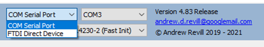
Depending on the
drivers that come with the cable it will either install into your system as an
FTDI Direct device, a Windows COM serial port or both. Avoid cables that claim
to have an ELM327 chip as these are a completely different interface, and
Galletto flasher cables as these seem to have the FTDI chips programmed
differently.
The whole suite of
applications now works with both FTDI Direct devices and any Windows COM serial
ports.
Connecting to the car, opening, saving,
reading and writing of files works almost identically to the way I described
for the MEMS3 Flasher. Exactly the same options are provided for reading and
writing firmware and/or maps to and from the ECU. The tool will prevent you
from writing a map to an ECU with a different firmware version. It will also
prevent you from writing a firmware or map with an incorrect checksum and will
offer to correct checksums automatically as necessary.
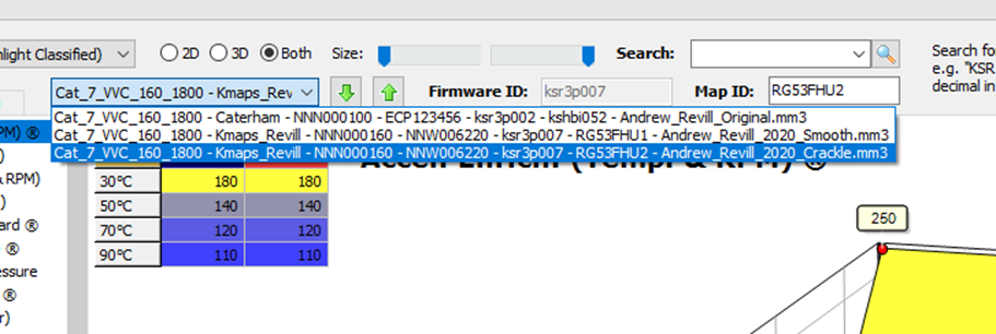
The main difference is that MEMS3 Flasher
only allowed you to open one file at a time. MEMS3 Mapper allows you to open
multiple files. You can move between the open files with Ctrl-Tab and Shift-Ctrl-Tab,
by selecting them from the combo box or by using the up and down arrow buttons.
This makes it very easy to compare tables between map files as it remembers
which table is selected in each file, so you can just tab between them looking
for changes.
There are
additional buttons to create a new file (which will create a new blank buffer
into which you can read a map) or to close the current file. If you close the
only file open, the buffer will be cleared and you will be left with a new
blank file.
OBDII Protocols
The application
supports two different protocols for communicating with the ECU. I identified
at least three protocols supported by the ECU, but one of them (ISO9141-2 with
Slow Initialisation Sequence) was hard to support over standard Windows COM
serial ports (due to the special slow pulse used as an initialisation signal)
and required the FTDI chipset or similar, and seemed to be more appropriate to
OBDII scanner tools, offering no particular benefits here, so I dropped support
for it. The other two protocols seem to be largely interchangeable but it’s
worth noting a couple of details here:
- ISO14230-2
with Fast Initialisation Sequence -
This is effectively the KWP2000 protocol. The ECU seems to be largely
compliant with the standard although there are a few deviations. It
operates at an ISO OBDII standard baud rate of 10400 bits per second.
There’s a special signal at a lower baud rate which is used to initialise
the ECU and start communications. There’s also a timeout, where if there
are no communications for a short time the ECU times out and needs to be
initialised again.
- Rover
BMW Protocol - This I am
guessing is the native protocol used to talk to the unit by Rover tools
such Testbook (but I’ve not been lucky enough to get my hands on one of
those to confirm - I could learn an awful lot more if I could). A lot of
the commands are the same as in the KWP2000 protocol, but the addressing
modes and checksum algorithms are different. It operates at a more
PC-standard baud rate of 9600 bits per second. There is no initialisation
signal and no timeout.
In practice it
makes very little difference which protocol you choose. I’ve worked around all
of the differences and fully implemented everything that I need to use on both
protocols. I’ve successfully flashed firmware and maps over both protocols
without issues, however there is one “gotcha” to bear in mind:
- When the ECU initially boots up, it talks
the Rover BMW protocol. Once the ECU has been initialised into the
ISO9141-2 or ISO14320-2 protocol, it will only talk ISO protocols until it
is rebooted. This is because there is no initialisation signal for the
Rover BMW protocol, so no way to signal to the ECU that you want to go
back to it.
- If you’re working exclusively in the
application and using once protocol consistently, this probably makes
little difference to you. However, if you are switching between the
application and other tools such as OBDII scanners (as I was during my
research), it is worth remembering that other tools will almost
exclusively use ISO protocol. So once you have plugged an OBDII scanner
into the ECU, it will only allow you to talk to it using the ISO14230-2
protocol until it is next rebooted or turned off for a period of time (on
my car it seems to need the ignition to be turned off for 9.5 seconds or
more - as a guide, the key seems to be that if it has been off for long
enough, the fuel pump will prime again when you switch it back on).
- When using this application with a USB OBDII
cable, I have sometimes found that after connecting the cable (and
sometimes after resetting the ECU too) the ECU would not communicate as
expected using the Rover BMW protocol. If I turned the ignition off for a period
of time then back on again, communication was restored. I have since
realised that the reason that the ECU would not communicate was that for
some reason it was switching to ISO14320-2 protocol. I think transient
signals on the K line as the connector pins made contact were being seen
by the ECU as ISO14320-2 protocol fast initialisation pulses.
I believe the
“professionals” generally program it using the Rover BMW protocol. Despite
initially recommending this protocol (for reasons which were mainly due to the
risks of “bricking” the ECU if ISO14320-2 protocol timeouts occurred during
write failures, which have now been completely eliminated) I would now suggest using the ISO14320-2 protocol for all mapping and
flashing operations. This generally leads to more reliable establishment of
communications with the ECU and better interoperability with other tools such
as OBDII scanners. I have been using ISO14320-2 protocol for most of my
research activities for some time now without any issues and the overall
experience is definitely better.
As of Version 4.51
Release of the application I have made ISO14320-2 the default protocol.
Memory Map
MEMS3 uses a 29F200 EEPROM chip.
Specifically it uses an AMD AM29F200BT-90SE variant. This is mapped into
externally accessible address space (as seen by OBDII) at base address $100000,
meaning that the different sectors of the EEPROM appear at the addresses shown
below.
Sector Size Address
Range Used For
SA0 64KB $100000 - $10FFFF Boot Loader
SA1 64KB $110000 - $11FFFF Firmware
SA2 64KB $120000 - $12FFFF
SA3 32KB $130000 - $137FFF
SA4 8KB $138000 - $139FFF
SA5 8KB $13A000 - $13BFFF Coding
SA6 16KB $13C000 - $13FFFF Map
Each sector of the EEPROM can only be
erased as a whole. Without erasing a sector (which sets every byte to $FF or
binary 11111111, logical 1's can only be programmed to logical 0's and not the
other way around, so it is not really possible to write arbitrary data to a
sector without erasing the data in the area to be written first, and this means
erasing the whole sector. Interestingly the "BT" in the chip
designation means "Boot Block at Top" - so the small 16KB sector SA6
at the top of memory is intended to hold boot loader code, which would be a small
application whose sole job is to communicate with some external tool to allow
the contents of the rest of the EEPROM to be loaded. In MEMS3, this sector SA6
is used for the map data which it relatively small and the bottom 64KB sector
SA0 is used for the boot loader code. The next 4 sectors SA-SA4, 64KB + 64KB +
32KB + 8KB = 168KB are used for the firmware code. The next 8KB sector SA5 is
used for what I have called Coding - this basically includes the VIN code and
the Part Variant.
As far as I can tell the ECU only
provides routines to erase the firmware and map sectors. So the boot loader
code is permanent and cannot be changed without corrupting it. This makes sense
as the boot loader code is what is executing when loading firmware or map data;
overwriting the boot loader while it was running would not make sense. This
doesn't seem to be a significant restriction, as any version of the boot loader
seems to work happily with my tool and will load any firmware version. The boot
loader code isn't involved in running the engine at all, so once the firmware
has been loaded and is running the older boot loader is irrelevant, and the VIN
and Part Variant code are informational only. The same is true of the Coding
data, so it is not possible to edit coding records written to this area; it is
however possible to add new coding records with new VIN code or Part Variant
code to the ECU and the application supports this. This is probably for
security, the original VIN number being indelibly written to the ECU.
The boot loader version on an ECU seems
to be consistent across ECUs with the same part number. So for example an early
VVC ECU NNN000100 will always have boot loader version bootp030 and a later VVC ECU NNN000160 will always have boot loader
version bootp033.
Runtime & Adaptations
Runtime data such as DTCs, adaptations
and immobiliser coding are stored in a separate 93C66 serial EEPROM chip. This
doesn't appear to be externally addressable; it doesn't appear as memory
addresses mapped into the memory space accessible to OBDII commands. I believe
data here will be read and written using higher level OBDII commands used to
request diagnostic information, or to request or set data by local identifiers.
I haven't been able to track all of these down, but I have managed to provide
workarounds which seem to be perfectly adequate. So for example when writing a
new map I clear the existing adaptations and when writing new firmware I clear
the immobiliser coding and allow the ECU to re-learn the code from the
immobiliser. I haven't had any issues using these workarounds in testing.
On Bench or In Car
The application has been written to allow
the ECU to be reflashed in the car through the OBDII port. You could also use a
simple bench testing harness such as the one I described here: https://andrewrevill.co.uk/KeyProgrammer.htm. Doing
it in the car is the easiest way and means that you don’t need to buy or build
expensive hardware. It also pretty much guarantees a reliable power supply. I’ve
done most of my development work on the bench then tested on my car.
If you flash the ECU in the car then as a safety precaution it's a very good
idea to disconnect the fuel pump (just unplug the inertia switch) and/or
injector sub loom. If a write fails or is interrupted, very occasionally
after turning the ignition off and on again the ECU will sit with one injector
turned on until it flashed again. If your fuel rail is pressurised, that could
go quite badly, pumping a lot of fuel into one inlet and risking a hydraulic
lock. It's very rare that it decides to do that but I've seen it before so
worth taking simple precautions.
Supply Voltage
Sites on the Internet seem to suggest that
you should never try to reflash any ECU at anything other than 13.5V. This
obviously precludes flashing the ECU in the car, as you can’t do it with the
engine running and the battery voltage alone will be well below that. I’ve
tested flashing ECUs with this application with supply voltages from 10.8V to
14.0V and everything worked correctly, although I wouldn’t recommend flashing
with a poor power supply. Some switch-mode power supplies generate huge amounts
of electrical noise, including on their “ground” line. This can lead to
communication problems on the bench, especially where a laptop is running off
mains supply and therefore has its own “ground” reference which won’t include
the noise. If you are using a bench power supply, make sure it’s a good clean
one. If you’re flashing it in the car, so long as the battery is reasonably
healthy it should be happy.
Connecting To The Vehicle
In a nutshell, connect to the vehicle as
follows:
- Do not
turn on the ignition yet. NB: If
you power up the ECU WITHOUT a diagnostic scanner or programming cable
plugged into the OBDII port, for some reason the ECU will not then talk to
any scanner of programming cable. You will need to either completely power
down the ECU or turn off the ignition for a period of time (on my car it
seems to need the ignition to be turned off for 9.5 seconds or more - as a
guide, the key seems to be that if it has been off for long enough, the
fuel pump will prime again when you switch it back on). This is a behaviour of the ECU itself and affects OBDII
scanners and other tools in the same way.
- Plug
the OBDII cable into the car's OBDII port and the PC’s USB port.
- Select
the OBDII cable using the combo boxes at the top of the window. It should
show up as either an FTDI Direct Device or COM Serial Port (or both, in
which case it should work fine whichever option you select). It may take a
few seconds for Windows to initialise the cable. When using a cable as an
FTDI device, if you receive an error message saying “Invalid handle for
FTDI device.” it usually means that the cable wasn’t ready yet and you
just need to wait a few seconds before trying again. You can also select
the OBDII protocol at this stage it required.
- Turn on
the ignition.
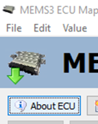
- Click About ECU to check your connection to the ECU.
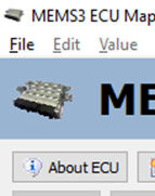
- You
should see green arrows flashing on the MEMS3 icon in the top left hand
corner, showing two-way communications with the ECU. If these arrows turn
persistently red there is a communications problem - after a short while
you will see an error message which should give a reasonable idea of what
the problem is. I’ve tried to make it capture the fine details of problems
and give helpful suggestions rather than just a blanket failure message. See the section on The Log Tab below
for more detailed information error diagnosis.
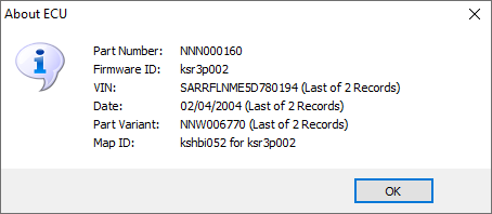
- If everything is working fine you should see
an information box like the one below, giving identifiers and versions for
the firmware and map loaded onto the ECU. If you get an error message such
as “ECU is silent.”, try turning off the ignition for a few seconds then
back on and try again (on my car it seems to need the ignition to be
turned off got 9.5 seconds or more - as a guide, the key seems to that if
it has been off for long enough, the fuel pump will prime again when you
switch it back on). Also note my
comments above that the ECU will not communicate using Rover BMW Protocol
if an OBDII scanner has been connected since it was powered up.
Reading The ECU
Once connected you can
read the existing map, with or without the firmware from the ECU.
Click the Read button. You should be
presented with a dialog like the one shown below:
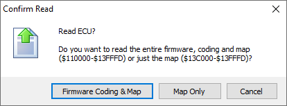
You can choose to read the full firmware
(contains the operating software of the ECU), coding (holds permanent records
contains the VIN and Part Variant plus other information) and the map (contains
the various tables and scalars with the configuration parameters for the
engine) or just the map. If you only read the map, you will be able to write
this back to any ECU with the same firmware version only. If you read the
firmware and map, you will be able to write this back to any compatible ECU.
You should see a progress bar as the read proceeds:
As I mentioned
before, unlike the MEMS3 Flasher tool, this application allows you to have
multiple files open at any one time. If you choose to read the Map Only in the dialog, the map data
from the ECU is read into the current
file. If you choose to read the full Firmware,
Coding & Map, it creates a new
file (unless an open file is already completely blank, in which case it
uses that).
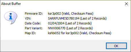
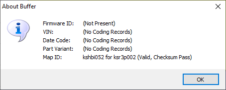
Once the read is
complete the system displays a dialog confirming the Firmware ID, VIN, Date
Code and Part Variant, (if these were read) and Map ID for the data in the
internal buffer. These should match the data originally displayed for the ECU.
The messages are all protected by checksums and the protocols I have
implemented include several layers of error checking and recovery so the data
should match in every case.
The pictures below
show the dialog after read the Firmware, Coding & Map (first image) and Map
Only (sec0nd image).
If the transfer is
interrupted, you should see that the Resume button becomes enabled. This will
allow you to resume and complete the read, even if the ECU has been shut down
in the meantime.
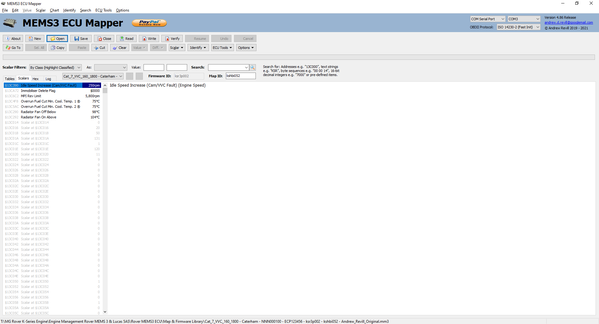
After reading the
ECU, the tool will display the tables and scalars in the map both in tabular
form and graphically. In the picture below you can see that there are tabs at
the top left for Tables and Scalars.
This is the Tables
tab:

And this is the
Scalars tab:
If the firmware
version in the ECU is one already known to the application, you will see the
known tables and scalars classified and listed at the top in black as shown
above (all of the unclassified tables and scalars are listed below in grey). If
not the system will prompt you to confirm that you want it to attempt to
identify tables and scalars automatically. Click Yes and the system will compare
each table loaded from the ECU with all tables seen previously and attempt to
assign the best matching table to each class. Depending on how closely the
tables resemble those previously seen in other firmwares, it may be able to
identify the correct table for every known class or it may not. Unfortunately
it only has the numerical data in the table and its position in the index to go
on as there is no unique identifier assigned to the tables in the map. It
compares the tables based on the extent to which the numeric ranges on the axes
overlap (i.e. to what extent is the table answering the same question), the
extent to which the values in the table agree (as the number of axis points may
vary it constructs a 100 by 100 mesh over the intersecting axis range between
the tables and interpolates values from each table at every point looking at
the extent to which they appear similar) and the closeness of the table
indices. For scalars, comparing a single number does not give enough for the
application to identify classes automatically. For example the number 7000
appears many times in the scalar data, one of them is the rev limit and the
others are not. Instead it looks for patterns in the surrounding scalars and
uses these to find the best match. In most cases it should get most of them
right, but you may have to manually correct it.
The system
continues to learn from any table and scalar classifications you assign. Each
time you classify a table or scalar or correct what it did, the information is
added to its library for use in classifying tables and scalars in the future.
The system
automatically adds any tables and scalars found in any files read or opened to
its reference library, but only provided that it detects that the map is a
virgin MG Rover map and not modified (this is to prevent any experimentally
modified tables from being added to the library leading to false matches in the
future). The system is able to distinguish between virgin and modified maps due
to the algorithm used for correcting map checksums when it has made
modifications. It applies a two byte signature ($4D, $4D hexadecimal which is
“MM” for “MEMS3 Mapper” in ASCII code) immediately after this; in a virgin
Rover ECU these bytes would always contain $FF. So any map where the checksum
is incorrect must have been modified (and not yet checksum corrected) as the
ECU would not have accepted a map with an incorrect checksum, any map with the
signature must have been modified (and the checksum corrected) and anything
else must be a virgin MG Rover map.
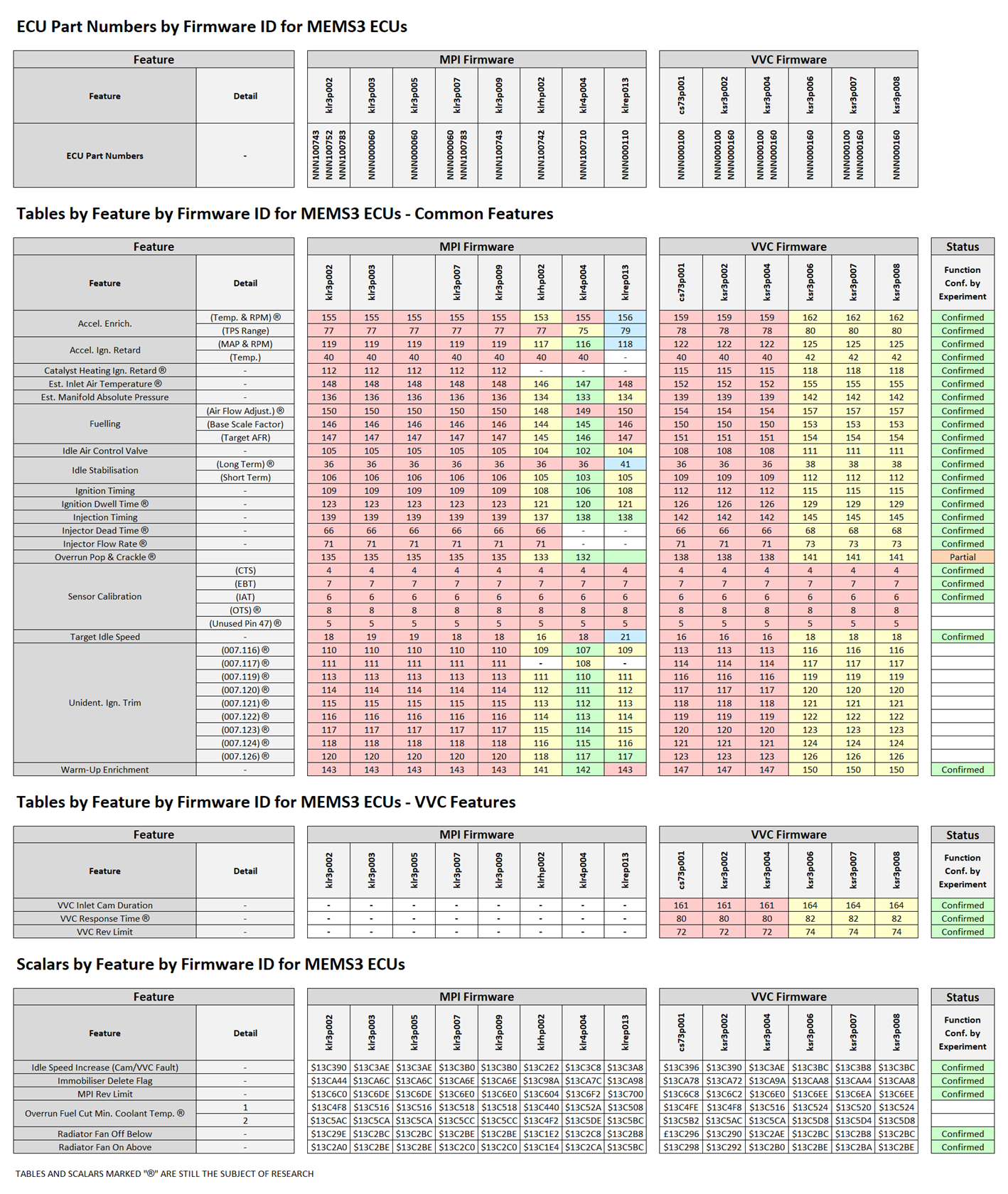
Bear in mind that
the index of a table with a given function tended to remain largely consistent
across multiple versions of the ECU firmware. The indices tended to increase
occasionally as additional table got inserted into the map, but when looking
for a table for a given function you should expect to find it in a very similar
position to that which it occupies in other ECU. Addresses of scalars follow
the same basic principle but are more subject to variation. The table below
shows the table indices for the tables and scalars I have identified so far for
a range of firmware versions for both MPI and VVC ECUs (some features are only
available on VVC ECUs).
Note that as of 15/04/2020 I have decided to focus my research
entirely on MG Rover or Caterham non-Turbo ECUs only. Although the application
works equally well with Land Rover and Turbo ECUs, the maps are sufficiently
differently structured to make it difficult to correlate tables and features
between them, although they are occasionally useful for reference (for example
to convince myself that the Est. Manifold Absolute Pressure table was what I
thought it was interesting to see that the Turbo ECUs had this table going well
above 100kPa into boost). As these ECUs are of significantly less interest to
us as Caterham owners I have left them out of my analysis of the maps for now
to allow me to focus on the features which are more of interest.
Saving & Opening
At this point you
may want to save the file read from the ECU to disk.
The MEMS3 Mapper and MEMS3 Flasher tools
load and save binary files with .MM3 or .BIN extensions. They support a number
of different types of binary files and recognise the type of file using both
the file extension and size. The following types are supported:
|
File Type |
Extension |
File Size |
Byte Order |
Description |
|
MEMS3 Flasher |
.mm3 |
196,606 Bytes |
Natural |
These are the native file format for
the application and contain the full firmware and map. This is the file
format you will use most of the time. |
|
MEMS3 Flasher |
.bin |
196,606 Bytes |
Natural |
These are identical to the above but
with a .BIN extension, and are supported to ensure that files saved by
previous versions of the application are recognised and opened correctly. |
|
MEMS3 Flasher |
.mm3 |
172,032 Bytes |
Natural |
These contain only the firmware with no
map. |
|
MEMS Flasher |
.bin |
172,032 Bytes |
Natural |
These are identical to the above but
with a .BIN extension, and are supported to ensure that files saved by
previous versions of the application are recognised and opened correctly. |
|
MEMS3 Flasher |
.mm3 |
16,382 Bytes |
Natural |
These contain only the map. |
|
MEMS3 Flasher |
.bin |
16,382 Bytes |
Natural |
These are identical to the above but
with a .BIN extension, and are supported to ensure that files saved by
previous versions of the application are recognised and opened correctly. |
|
Galletto |
.bin |
16,383 Bytes |
Natural |
These files are compatible with the
Galletto remapping tool. They are identical to the above but with a .BIN
extension and one of the two unreadable $FF bytes at the end of the map is
present. |
|
EEPROM Reader |
.bin |
262,144 Bytes |
16-Bit Byte-Swapped |
These contain the full boot loader,
firmware and map. They are files obtained by reading the EEPROM chip on an
EEPROM reader off the board as I did in my original article. You will need to save using this format
if you intend to program the file into a 29F200BT EEPROM chip using and
EEPROM programmer and then solder it into an ECU. Because of the way the
microcontroller addresses 16-bit memory, each pair of bytes in this kind of
file is exchanged. Note that of you
choose to save a full EEPROM file, a boot loader will be required (the
application only normally handles the firmware, coding and map areas). You
will be prompted to select a boot loader file which will be inserted into the
file saved. |
|
Boot Loader |
.bin |
65,536 Bytes |
16-Bit Byte-Swapped |
These contain the boot loader only.
They are used only when saving a file in EEPROM Reader (Byte-Swapped) format
as described above. Because of the way the microcontroller addresses 16-bit
memory, each pair of bytes in this kind of file is exchanged. Boot loaders
are 64kB in size, but the file you provide may be larger, in which case only
the first 64kB will be used. This allows a boot loader contained within an
EEPROM Reader (Byte-Swapped) file to be used directly. A selection of boot
loaders is supplied with the application. Ideally you should use the correct
boot loader for the NNN part number of your ECU, although certainly for
petrol ECUs something like bootp033
(NNN000160, VVC 160 ECU boot loader) seems to work with other hardwares and
firmwares. Diesel ECUs use the part number in the boot loader to determine
the high-side switch driver used and so it is important not to mix boot
loaders between NNN000XXX and NNN500XXX ECUs. |
In normal use, you would probably only
need to use the MEMS3 Flasher Default files.
As I mentioned
before, unlike the MEMS3 Flasher tool, this application allows you to have
multiple files open at any one time. If you later choose to open a file which
contains only partial EEPROM contents (i.e. a Firmware File or a Map File as
described above), the data from the file is read into the current file. If you
choose to open a file which contains the full firmware, coding & map (i.e.
a Flasher File or EEPROM file as described above), it creates a new file (unless
an open file is already completely blank, in which case it uses that).
The ten most
recently accessed files are available on the File, Recent menu. Click on one of
these to re-open the file.
Writing To The ECU
Once you have made
modifications to the map, you will need to write it back to the ECU. There is
no “live updates” mode supported, the ignition must be turned on but the engine
must not be running in order to write a modified map back to the ECU. The
writing process initially erases the firmware or map being written; to do this
it runs in a protected boot loader in the ECU and all normal engine management
features are suspended.
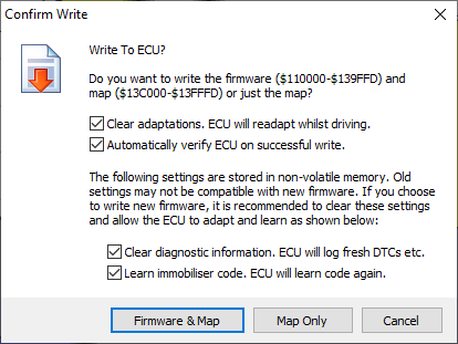
The process of writing to the ECU is very
similar to the process of reading an ECU. Click the Write button. You should be
presented with a dialog like the one shown below. Again you can choose to write
the full firmware and map or just the map alone. If you choose to write just
the map, the application will check the firmware in the ECU to make sure it is
the same version as the one the map is compiled for and will refuse to write an
incompatible map to the ECU.
There are a few
extra options when writing:
Clear adaptations. This will clear any adaptations in the
ECU, as they may not be appropriate with a modified map. The ECU will readapt
over a couple of hundred miles of mixed driving. During this time the emissions
and fuel economy may not be as good as they normally are as the fuelling may be
slightly incorrect.
Automatically verify ECU on successful write. This will cause the application to perform a read of the ECU once
the data has been written, to confirm that the data now in the ECU matches that
in the buffer. This is a bit of a "belt and braces" solution as the
ECU appears to verify internally that each block is written correctly as
received and the communications use checksums to allow the ECU to confirm that
each message received is as it was sent, so other than for failures of the
software or very unlucky corruptions that leave the checksums unchanged, the
data transfer should be reliable. By default this is now set not to verify.
Clear diagnostic information. This
option only applies when writing the firmware. Because I can't be sure that the
format used for storing information in the working non-volatile memory of the
ECU is identical or compatible between firmware versions, by default the
application clears any diagnostic information. The ECU will then continue to log
new diagnostic information for any current faults.
Learn immobiliser code. Again this
only applies when writing the firmware. Again, as I cannot guarantee that the
format used for storing the immobiliser code will always be compatible between
firmware versions, by default the application clears the immobiliser coding and
tells the ECU to re-learn it from the immobiliser. The ECU will then be
free-running initially but the first time it sees the immobiliser disarmed it
will learn the code and again be paired with that immobiliser.
Due to the fairly low serial data speeds
used by the protocols supported by the ECU, writing the map alone takes up to
about 24 seconds to write and up to about 22 seconds to verify, so up to 46
seconds in total. Performing a full write of the ECU takes up
to about 3 minutes 44 seconds to write and up to about 4 minutes 19 seconds to
verify, so just over 8 minutes in total. The ECU will reboot at the end
of the write, you will hear the fuel pump priming as though the car ignition
was just turned on. You should see a progress bar as the write proceeds:

Try not to
interrupt the process of writing to the ECU as the ECU will not run the engine
with only a partial firmware or map. If the process is interrupted, you will
see an error message like this (in this case I pulled the USB connector out of
the back of my laptop mid-write):
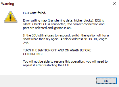
The writing process is now fail-safe. The
ECU will be left in a non-running state and will in all likelihood fail to
communicate with the application, but this is only because it will be in the
middle of a data transfer and will not be expecting other commands. All you
will need to do to restore normal communications is to turn the ignition off
and on again. You will notice that the fuel pump will not prime as normal as
the ECU will continue to run the boot loader only and will not run normal
engine management operations. Once you have cycled the ignition and made sure
that the issue with the connection to the ECU has been rectified (e.g. any
cable that got pulled out has been plugged back in again), you can simply
repeat the write operation. See the
section on Fail Safe Read &
Write at the top of this write-up for further information.
AS OF VERSION 4.87 THERE IS A NEW FUNCTION ON THE ECU TOOLS MENU TO
RECOVER A BRICKED ECU. This should allow
full and easy recovery of an ECU that has been bricked by any of the methods
above (or in any other way, including using other programming tools, no matter
how badly the firmware and map have become damaged). See the sections on ECU Tools and Recover Bricked ECU below for more
information.
Views & Filters
The application is
a bit of hybrid between a remapping tool and a research tool for use by me in
decoding the maps. As such, it shows you all of the tables and scalars found in
the ECU and provides the tools to allow you to filter them down to find ones
that are relevant. The filters provided for tables and scalars are slightly
different.
![]()
For tables, in
addition to viewing only 2D or 3D tables and limiting the maximum and minimum
table size with sliders, you can choose one of the following basic views:
- By
Index (Highlight Classified) -
This display all tables found in the map. All tables are sorted by index.
Tables which have been classified are highlighted in black in the list and
any unclassified tables are shown in grey.
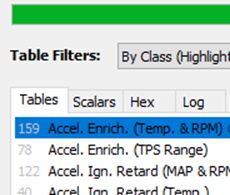
- By
Class (Highlight Classified) -
This is the default view. This displays all tables found in the map. It
puts the tables which have been classified at the top of the list in black
and any unclassified tables below in grey. The classified tables are
sorted alphabetically on their descriptions,
unclassified tables are sorted by index.
- Clean
(Classified Only) - If you are
not interested in looking for further tables, this cleans up the display
and shows only the classified tables.
![]()
For scalars, the
basic view options are the same but the filter options allow you to list only
those which lie between minimum and maximum values. You can specify either a minimum value, a maximum value or both.
Unclassified scalars are sorted by address.
As the values of
scalars are often stored using a scale factor and an offset (e.g. temperature a
value of 20°C is stored in tenths of a degree Kelvin as (20+273.2)*10 = 2932),
you also have the option of viewing all unclassified scalars as any axis class
you choose (classified scalars are always displayed using the axis class
assigned to them). The minimum and maximum value filters are then applied to
the correctly scaled values.
Search
I’ve implemented a
Search facility that will search the EEPROM data for any of the following:
- Hexadecimal addresses in the EEPROM data,
e.g. 13C000 or $13C000.
- Text strings such as e.g. KSR. These may
appear in version IDs etc.
- Sequences of bytes, e.g. 00 00 14 or $00 $00
$14.
- 16-bit Integer values, e.g. 7000. Hint: If you want to search for a
16-bit decimal integer which is two digits or less e.g. 10 and you don’t
want it to match the hexadecimal byte $10, enter it as a 3 digit number
e.g. 010.
You don’t need to
specify what kind of item you area searching for, just type what you want to
search for in the box and press ENTER
or click the Search button. It will
find the first address that matches the text you typed as any one of the above.
F3 will repeat the last search provided that it was successful, finding the
next instance which matches.
You can also search
for any of the following pre-defined items from the drop down list:
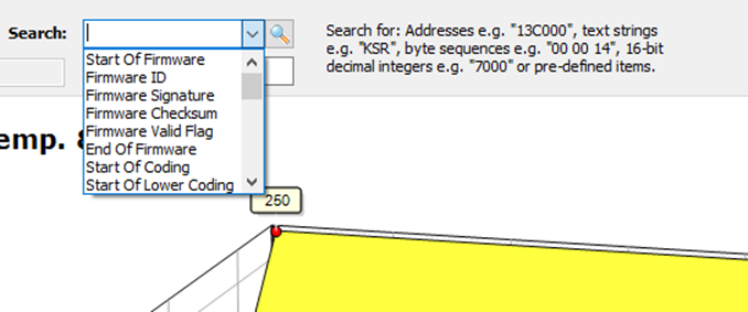
- Start
Of Firmware - This takes
you to the first address of the firmware, which is $110000.
- Firmware
ID - This takes you to the fixed address
where the firmware ID is stored, which is $110400. Note that the 8
character firmware ID is actually stored in 16 bytes, with each character
being repeated twice (no idea why).
- Firmware
Signature - This takes you to the fixed
address where the firmware signature is stored, which is $110410. The
firmware signature should be $5AA5. The ECU boot loader checks this
signature to determine whether a firmware is loaded.
- Firmware
Checksum - This takes you to the fixed
address where the application corrects the firmware checksum, which is
$139FF0. Note that is not the address used by MG Rover. I suspect that the
last two bytes of the firmware before the unused $FF bytes are probably
the address where MG Rover corrected the checksum, but as I haven’t been
able to identify a clear “length of firmware” anywhere I didn’t feel it
was safe to overwrite these bytes. Instead I’m correcting the checksum at
a high address towards the top end of the firmware address space. This
seems to work fine. I avoided the last few bytes just in case these were
ever used for anything. In reality you are very unlikely to modify the
firmware data, so the checksum will not need to be updated. The checksum
algorithm is as follows: The 16-bit sum of the 86,016 16-bit words (high
byte first) at hexadecimal addresses $110000/1 to $139FFE/F is always
equal to $04FB.
- Firmware
Valid Flag - This is very
last byte of the firmware area. It should normally contain $FF for a valid
block. It is set to $00 before reading the firmware from the ECU or from a
disk file. If the read then fails to complete, it will be left containing
$00 which marks the firmware as invalid. If the read completes but the
checksum is found to be incorrect, this byte is reset to $00 which marks
the firmware as invalid again. A firmware marked as invalid CANNOT BE
WRITTEN TO THE ECU. This mechanism protects against cancelled, failed,
partial or incorrect reads from the ECU or disk file and corrupted files.
- End Of
Firmware - This takes you to the last
address in the firmware address space which is $139FFF.
- Start
Of Coding - This takes you to the first
address in the coding area, which is $13A000. The coding area holds two
different kinds of records, which I have called lower coding records
(starting at address $13A000) and upper coding records (starting at
address $13B000). The coding records look like they were written to the
ECU whenever it was reprogrammed by Rover. Most ECUs only have a single
lower coding record, although some have two which suggest that these ECUs
were reprogrammed with updated maps or firmware at some point. The lower
coding records contain (amongst other unidentified information) the date
on which the record was programmed and the VIN and Part Variant codes (a
part number usually starting with NNW, which identifies the combination of
hardware and software builds, whereas the Part Number starting with NNN
identifies the hardware build only). I haven’t identified anything
particularly interesting in the upper coding records. As far as I can
tell, the coding area cannot be erased (i.e. the ECU doesn’t provide a
routine to erase it, the only way to erase to it would be to crack the ECU
open and desolder the memory chip and reprogram it on a PC). I think the
idea is that the coding records form a permanent, indelible record of the
ECUs history. You can only add new records after the existing records, you
cannot erase or update (without corrupting, as you can only reprogram
binary 1s to 0s and not the other way around without erasing) existing
records. The MEMS3 Mapper application allows you to add lower coding
records to the ECU with your own VIN and your own Part Variant codes if
you wish. I have coded modified ECUs to my car’s VIN number and used the
Part Variant ADR999999. The first 3 characters can be alphabetical or numeric, the last 6 characters must be numeric digits
(they are stored as 2 digits per byte in BCD coding). See the sections on ECU Tools and Write Coding Record below for
more information.
- Start
Of Lower Coding - This takes
you to the first address in the lower coding area, which is $13A000 (the
same as Start of Coding). See
above.
- VIN - This takes you to the address of the VIN
in the LAST lower coding
record. If there is only one coding record, this will be $13A000, but it
will be higher if there are two records or more. If there is more than one
lower coding record, the last one written takes precedence over the
previous records.
- Date - This takes you to the address of the
programming date in the LAST
lower coding record. If there is only one coding record, this will be
$13A00E, but it will be higher if there are two records or more. If there
is more than one lower coding record, the last one written takes
precedence over the previous records.
- Part
Variant - This takes you to the address of
the Part Variant in the LAST
lower coding record. If there is only one coding record, this will be
$13A014, but it will be higher if there are two records or more. If there
is more than one lower coding record, the last one written takes
precedence over the previous records.
- End Of
Lower Coding - This takes
you to the last address in the lower coding area, which is $13AFFF See above.
- Start
Of Upper Coding - This takes
you to the first address in the upper coding area, which is $13B000. See above.
- End Of
Upper Coding - This takes
you to the last address in the upper coding area, which is $13BFFF. See above.
- Coding
Valid Flag - This is very
last byte of the coding area. It should normally contain $FF for a valid
block. It is set to $00 before reading the coding from the ECU or from a
disk file. If the read then fails to complete, it will be left containing
$00 which marks the coding as invalid. If the read completes but the
checksum is found to be incorrect, this byte is reset to $00 which marks
the coding as invalid again. A coding marked as invalid CANNOT BE WRITTEN
TO THE ECU. This mechanism protects against cancelled, failed, partial or
incorrect reads from the ECU or disk file and corrupted files.
- End Of
Coding - This takes you to the last
address in the coding area, which is $13BFFF (the same as End of Upper
Coding). See above.
- Start
Of Map - This takes you to the first
address of the map, which is $13C000.
- Map
Length - This takes you to the fixed
address where the 16-bit map length is stored, which is $13C000 (the same
as Start Of Map).
- Map ID - This takes you to the fixed address where
the Map ID is stored, which is $13C002. Note that if you produce a
modified map you can edit the Map ID in the edit box provided. The map ID
you enter here is written back into the map memory addresses and will be
flashed onto the ECU when you flash the map:
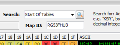
- Map
Firmware ID - This takes
you to the fixed address where the Map Firmware ID is stored, which is $13C00A.
The Map Firmware ID is the Firmware ID for which the map was built; you
cannot write a map to the ECU which was built for a different firmware
version as all of the scalar addresses will be wrong, and the table index
and structure of the tables will not correspond.
- Map
Signature - This takes you to the fixed
address where the map signature is stored, which is $13C012. The map
signature should be $5AA5. The ECU boot loader checks this signature to
determine whether a map is loaded.
- Start
Of Scalars - This takes
you to the first address of the scalar data in map, which is $13C014. Note
that this may or may not be correct. I have assumed that everything
unidentified which precedes the table data is scalar data. It may however
be that some of the earlier addresses are used for other specific
purposes. By making all of it available as scalar data I was erring on the
safe side. If I identify further structures in this memory area, I may
adjust the Start Of Scalars and End Of Scalars in
future versions. The scalar data is generally easy to recognise as it
tends to consist mainly of “round numbers” in decimal. The tables are all
packed in memory one after another without any gaps and it looks to me
like the scalar data is handled in the same way.
- End Of
Scalars - This takes you the last address
used for scalar data in the map. This address is not fixed, but is
identified as the address which immediately precedes the first table (in
reality I presume that when building the firmware loads for the ECU the
compiler worked out how many scalars were used and stacked them one after
another, then stacked the tables one after another after the scalars, then
wrote out a table index which told the ECU where each table was located as
the table sizes can vary between different maps for the same firmware
version, however we need to work backwards so we read the table index to
locate the tables and the last scalar address must be the address
preceding the first table). Note that the microcontroller in the ECU
appears to use 16-bit aligned values exclusively; this is to say that any
number stored in the EEPROM data will always consist of two bytes, the
first being the high order 8 bits in an even numbered byte and second
being the low order 8 bits in the odd numbered byte following it. End of
Scalars will always therefore take you to an odd numbered address, the last actual scalar will be stored at the
preceding address.
- Start
of Tables - This takes
you to the first address used for table data in the map. This address is
not fixed. See above.
- End of
Tables - This takes you to the last address
used for table data in the map. This address is not fixed. See above.
- Map
Table Index - This takes
you to the start of the map table index. This address varies between
different firmware versions but is always the same in different maps for
the same firmware version. The compiler would have just compiled this
address into the firmware. Again we have to work backwards. The map length
tells us where the map file ends, and the table index is the last thing in
the map. Between the end of the tables and the index there is unused space
filled with $FF (erased state) bytes. The table index contains 16-bit
offsets from the start of the map to the address of each table. So for
example if the entry at index 0 in the map index contains the hexadecimal
integer $35AA this tells us that table with index 0 is at address $13C000
+ $35AA = $13F5AA. As the map address space is only 16KB, $FFFF cannot be
a valid offset to a table. So to find the table index, we start at the end
of the map and work backwards until we find $FFFF. The address immediately
after the first $FFFF found this way is the start of the table index.
- Map
Checksum - This takes you to the last two
bytes of the map, according to the declared map size. These two bytes are
used to correct the checksum for the map. The checksum algorithm is as
follows: The 16-bit sum of the 8192 16-bit words (high byte first) at
hexadecimal addresses $13C000/1 to $13FFFE/F is always equal to $004C.
- Map
Modified - This takes you to the two bytes
immediately following the map checksum. The application uses these two
bytes to determine whether the map is a virgin MG Rover map or whether it
has been modified. The system is able to distinguish between virgin and
modified maps due to the algorithm used for correcting map checksums when
it has made modifications. It applies a two byte signature ($4D, $4D
hexadecimal which is “MM” for “Map Modified” in ASCII code) immediately
after this; in a virgin Rover ECU these bytes would always contain $FF. So
any map where the checksum is incorrect must have been modified (and not
yet checksum corrected) as the ECU would not have accepted a map with an
incorrect checksum, any map with the signature must have been modified
(and the checksum corrected) and anything else must be a virgin MG Rover
map.
- Map
Valid Flag - This is very
last byte of the map area. It should normally contain $FF for a valid
block. It is set to $00 before reading the map from the ECU or from a disk
file. If the read then fails to complete, it will be left containing $00
which marks the map as invalid. If the read completes but the checksum is
found to be incorrect, this byte is reset to $00 which marks the map as
invalid again. A map marked as invalid CANNOT BE WRITTEN TO THE ECU. This
mechanism protects against cancelled, failed, partial or incorrect reads
from the ECU or disk file and corrupted files.
- End Of
Map - This takes you to the last
address in the map area, which is $13FFFD. The last two bytes $13FFFE/F of
the EEPROM are inaccessible over OBDII for some
reason. You can neither read nor write them, the ECU denies access. I have
no idea why, because I’ve inspected them by dismantling ECUs, desoldering
the memory chips and reading them on the PC; they are always just unused
bytes containing $FF just like the bytes leading up to them.
Go To
In addition to the Search facility, I’ve implemented a Go To feature.
This allows you to go to the memory address for any table (in fact any cell in
any table) or any scalar. It works both ways; highlight a cell or scalar and
click Go To and it takes you to the
corresponding memory address in the Hex
tab, highlight a memory address in the Hex
tab that is associated with a table or scalar and click Go To and it takes you to the view of the corresponding table or
scalar. Go To is found on the main
menu, on right click popup menus throughout the application and as a button on
the button bar. See the section on the
Hex Tab below for more information.
The Hex Tab
The Hex tab shows you the raw contents of
the EEPROM memory in a hexadecimal grid format.
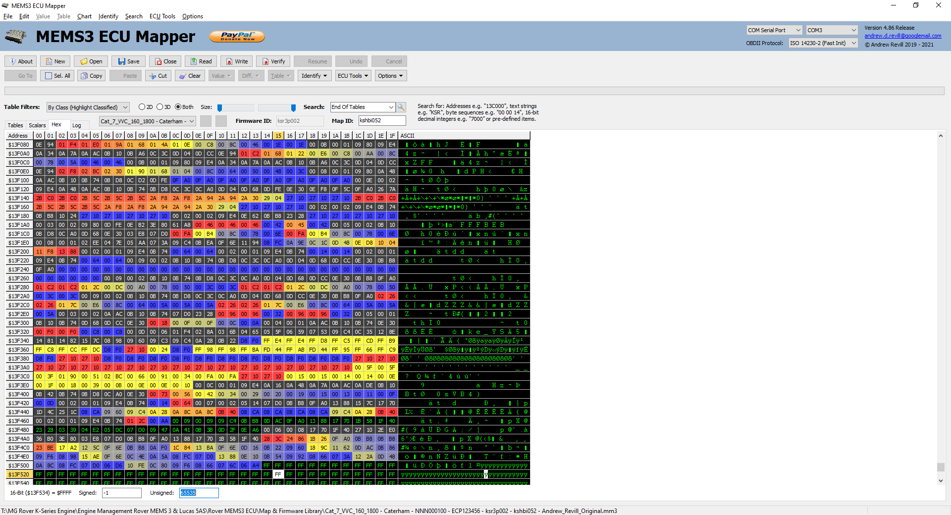
This is an
extension of the hexadecimal data display in the MEMS3 Flasher application. It
shows the memory contents, 32 bytes per row, in both hexadecimal and ASCII
character format.
You can edit the
memory contents directly in the Hex
tab or you can edit tables and scalars in the other tabs. Either way is
equivalent; if you edit a table you will see the memory changes immediately in
the Hex tab and if you edit the
memory contents in the Hex tab you
will see the changes immediately in the corresponding table or scalar. If you
edit the map or firmware in raw hexadecimal format there is no way for the
application to prevent you from creating something which may damage the ECU, so
USE THIS FEATURE WITH GREAT CAUTION AND
ONLY ATTEMPT TO WRITE BACK A MAP WHICH YOU HAVE EDITED IN THIS WAY IF YOU
REALLY UNDERSTAND WHAT YOU ARE DOING! As of version 4.85, the first time
you attempt to edit a map or firmware in raw hexadecimal format within a
session you will be given a warning as shown below. You need to click Yes in order to allow raw hexadecimal editing. By default
the No button is highlighted.
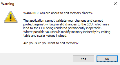
AS OF VERSION 4.87 THERE IS A NEW FUNCTION ON THE ECU TOOLS MENU TO
RECOVER A BRICKED ECU. This should allow
full and easy recovery of an ECU that has been bricked by any of the methods above
(or in any other way, including using other programming tools, no matter how
badly the firmware and map have become damaged). See the sections on ECU Tools and Recover Bricked ECU below for more
information.
You will see that
every memory address with an identified meaning is highlighted in an
appropriate colour. For tables, the colours reflect the shading of the cells in
the table display. If you hover the mouse over any
memory cell, you will see a hint window which tells you exactly what that
memory address is used for:
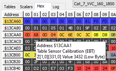
With any byte
selected you will also see a decode at the bottom of
the page showing the corresponding 16-bit value. Note that the microcontroller
in the ECU appears to use 16-bit aligned values exclusively; this is to say
that any number stored in the EEPROM data will always consist of two bytes, the
first being the high order 8 bits in an even numbered byte and second being the
low order 8 bits in the odd numbered byte following it. So you will see the
same 16-bit number for each pair of consecutive even and odd numbered
addresses. The value is shown decoded from hexadecimal as both signed and
unsigned 16-bit integers, and you can edit the values in either of these forms;
any changes you edit here are written back to the memory using the appropriate
convention and you will immediately see that changes in any tables or scalars
affected.
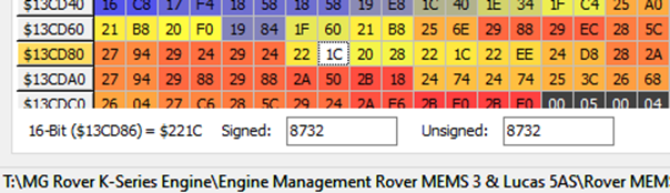
The Go To button will take you to the table
or scalar associated with the selected memory address, in the same way that it
will take you to the memory address for a given table cell or scalar.
If you apply
filters to the tables or scalars as described above, then only those which meet
the filter criteria are highlighted within the memory grid.
You can highlight
contiguous ranges of memory addresses by dragging with the mouse, or using Shift and Ctrl on the keyboard in the usual way. You can click Select All to select all memory
addresses. The Copy, Paste, Cut and Clear buttons
work on the selected range of addresses. Select
All, Copy, Paste, Cut and Clear are found on the main menu, on
right click popup menus throughout the application and as buttons on the button
bar. Memory cells are copied to the clipboard as address, value pairs in
hexadecimal:
$13CC0B $3E
$13CC0C $00
$13CC0D $4E
$13CC0E $00
When cutting or
clearing cells, they are set to $FF. This is the state of memory cells in a new
EEPROM chip or after erasing a sector and is the value stored in every unused
memory address in the EEPROM.
Note that the clipboard formats used are all plain text formats, you
can for example Copy Table Data and paste the copied table into an email; the
recipient can then copy the data from the email and paste it into a table.
The Tables Tab
The Tables tab gives you both a tabular
view and a graphical view of each table in the map.
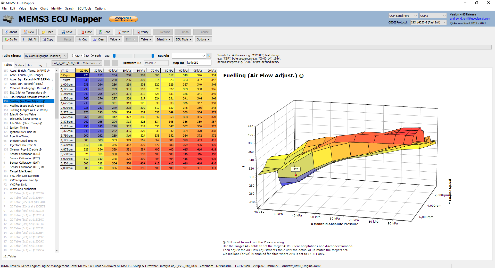
On the left hand side
you will see the list of tables found in the index. This is sorted and
highlighted according to the rules described previously. See the section on Views & Filters for more information.
In the centre you
will see the table displayed as a grid. You can edit values in the grid and
changes are written back to memory immediately.
You can highlight
rectangular ranges of cells by dragging with the mouse, or using Shift and Ctrl on the keyboard in the usual way. You can click Select All to select all cells in the
table. The Copy, Paste, Cut and Clear buttons
work on the selected range of addresses.
Select All, Copy, Paste, Cut and Clear are found
on the main menu, on right click popup menus throughout the application and as
buttons on the button bar.
Note that there two
Copy options which do different things:
- Copy - The usual Copy button just copies the selected cells in a standard
tab-separated multi-line format which may then be tasted in Excel or
anything similar. Copy is found
on the main menu, on right click popup menus throughout the application
and as a button on the button bar and is accessible through the shortcut Ctrl-C.
- Copy
Table Data - This copies
the entire table definition, including the axes. This then allows you to
paste the entire table into another map, completely replacing the table
already there. This is true even
where the table size is different - the application takes care of moving
everything else around in memory to accommodate the new table size and
then updates the table index to point to the new table addresses. Copy Table Data is found on the
main menu, the right-click popup menu on the table grid and on the drop
down menu on the Table button
on the button bar.
In order to
maximise the amount of data that can be displayed, tables in the application
are always displayed with the longer axis of X and Y (i.e. the one with most
defined values) going down by default. So sometimes a table will have the X
axis across and the Y axis down and sometimes it will have the X axis down and
the Y axis across. The top left hand cell in the display shows you the
orientation, although once you have classified a table it doesn't really matter
as the designations "X" and "Y" only really relate to the
order in which the values are stored in memory - as a user you will work in
terms of the MAP axis and the RPM axis. For ease of data visualisation, the
application does allow you to transpose the orientations of the X and Y on the
table and chart, and also allows you to invert (reverse the direction of) the
axes on the chart. By default the depth axis of the chat is inverted (numbers
increasing from the back towards the front) as this gives a layout of points in
the chart which most closely corresponds to the layout of the numbers in the
table. Transpose is found on the
main menu, on the right-click popup menu on the table grid and on the drop down
menu on the Table button.
By default the axis
cells in the grid are locked and you cannot change the axis values. If you want
to be able to edit the axes, select Edit
Axes, which is found on the main menu, on the right-click popup menu on the
table grid and on the drop down menu on the Table button. This will unlock the axis cells for both the
horizontal and vertical axes and allow you to edit the values. In addition, once
the axes are unlocked for editing, if you click on a cell in either axis you
will then see options on the main, popup and drop down menus for Insert Axis Value and Delete Axis Value. These allow you to
change the size of the table by inserting and deleting values on the axes - the application takes care of moving
everything else around in memory to accommodate the new table size and then
updates the table index to point to the new table addresses. I have tested
this on a number of ECUs and they seem quite happy to accept tables of
different sizes and apply them correctly. There are a few points to note
though:
- Table map space in memory is limited. The
amount of free available map space between the last table and the table
index varies between maps for the same firmware version due to the
different table sizes used, and between firmware versions due to the
different numbers of scalars and the different addresses used for the
table index. For some reason the table index wasn’t placed right at the
top of the available memory, leaving limited space for the tables to grow.
VVC firmwares tend to put the table index at a higher address leaving more
room for table expansion. In addition, because my application is forced to
locate the start of the table index by finding the $FFFF preceding it,
there needs to be at least 2 bytes left unused. The table below shows some
examples of the number of bytes of available space on one example map per
firmware version that I have looked at.
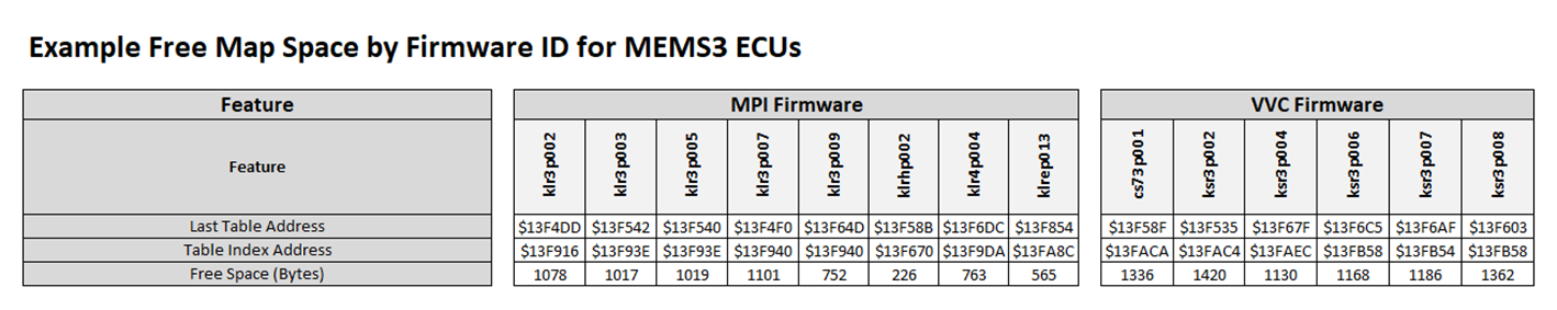
As an
example, the number of extra bytes required to insert an additional value into
the X axis of a large table which currently has 10 X values and 12 Y values is
2 (for the new X axis value) plus 2*12=24 (for the new cells, one per Y axis
value) so 26 in total. You can see that even in the most limited case above
there is still quite a bit of scope for inserting values where they are
required.
- You cannot insert a value into an axis that
currently only has one value. Similarly you cannot delete a value from an
axis that currently has two values. This is because an axis with 1 value
makes the table 2D rather than 3D and you cannot change the dimensionality
of a table otherwise the ECU would not understand it.
- In order for the ECU to be able to
interpolate values, the values along an axis must be in order. My
application will handle the cases where the axis value
are all in increasing order or all in decreasing order. It will
even accept tables where all the axis value are the
same. But as far as I have seen the ECU only ever uses axes I which that
values appear in order of increasing value (but if a table is ever
encountered that has decreasing axis values the application will handle it
correctly). This means that you don’t get to choose where to insert a
value on an axis, you just enter a value and the application inserts it in
the correct position. Similarly you cannot edit an axis value such that it
becomes out of sequence.
NB: Although it is can lead to multiple possible lookups for the same key values, I have explicitly allowed duplicate adjacent axis values. I have done this simply because some virgin MG Rover maps have been found to have duplicate values. The only cases I have seen in MG Rover maps have been 2D temperature sensor calibration curves, and in all cases where an X value has been duplicated the Z values for the duplicate points have been the same. Be aware that for example introducing duplicate X values with different Z values may introduce inconsistencies and lead to unpredictable ECU behaviour. - When you insert an axis value, the initial
values in the cells are generated automatically by the application by
interpolating between the old values, or extrapolating where the new value
extends one end of the axis. So for example in the example below the table
has MAP axis values for 80kPa and 90kPa:
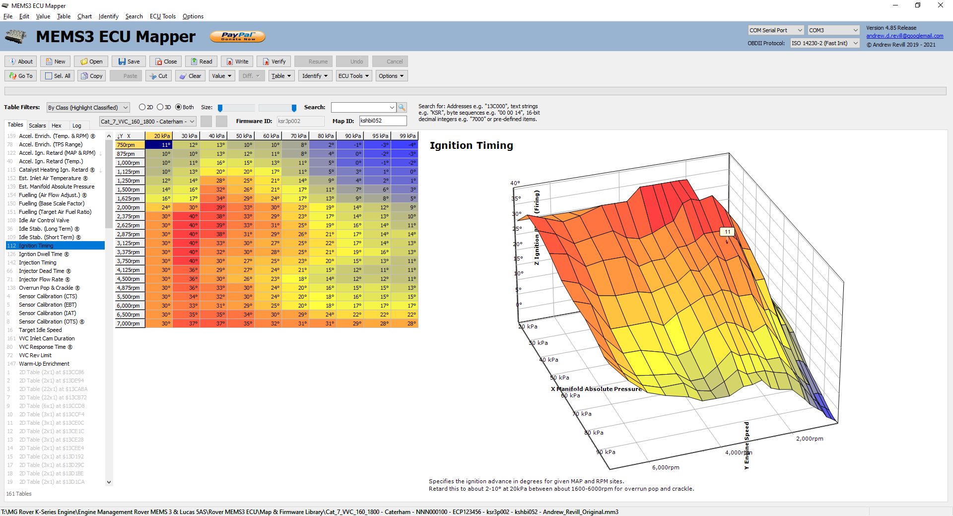
If I then insert a new axis value for 85kPa it looks like this:
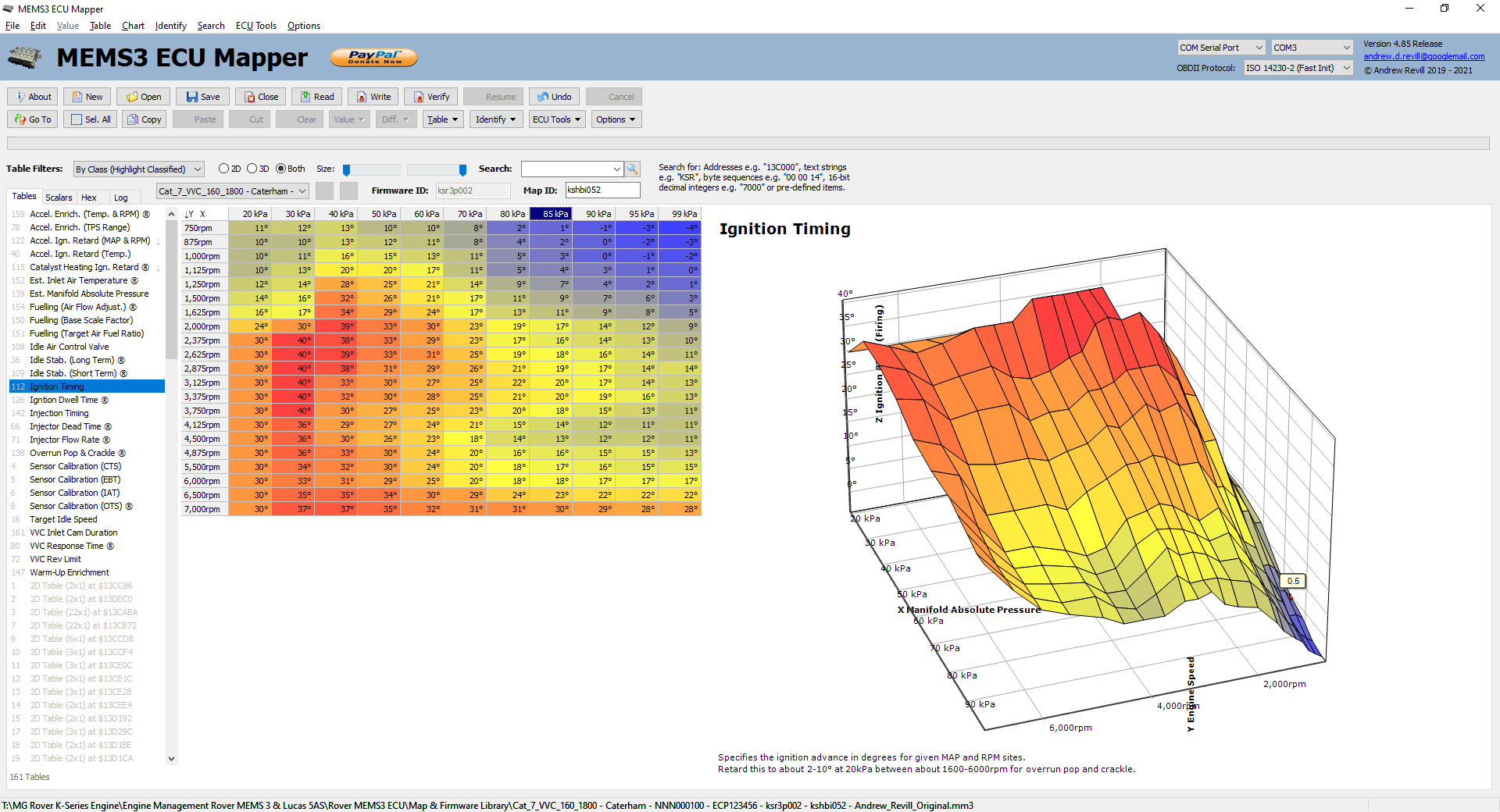
You can see
that the new axis value 85kPa has sensible ignition timings associated with it
and that despite a new column of values appearing, the new grid line on the
chart follows the original profile and the shape of the ignition curve is
unaltered:
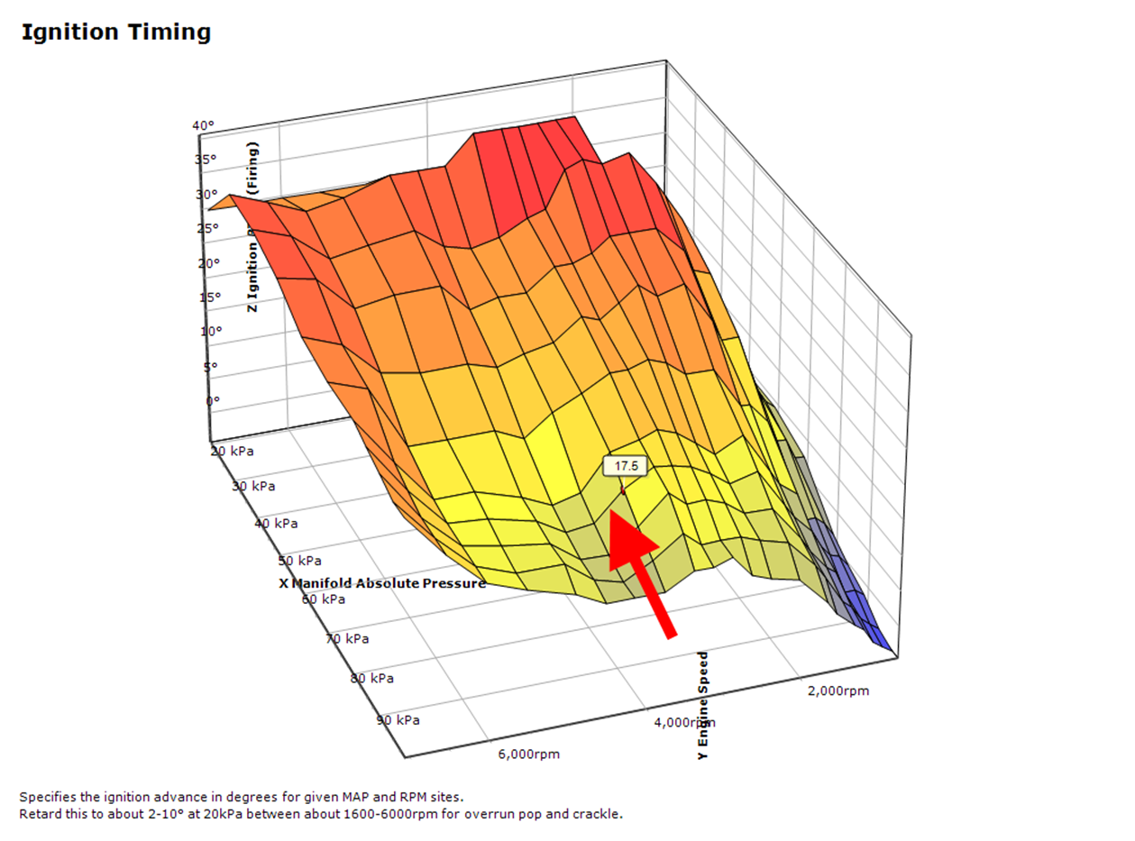
You can then edit the values for the new 85kPa axis value as required.
You also have the
option of displaying Raw Values.
When displaying raw values, none of the axis formatting (scaling, offsetting or
number formatting) is applied. Values are displayed as 16-bit signed integers,
exactly as they appear in the table memory. When raw values are displayed, you
also edit and enter numbers in raw format too. For example here is injector
scaling table displayed normally with formatting (first image) and as raw
values (second image). Raw Values is found on the
main menu, on the right-click popup menu on the table grid and on the drop down
menu on the Table button.

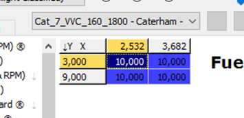
On the right you
will see the table displayed as a chart. In the case of a 3D table and chart,
you can rotate the chart in three dimensions by dragging with the mouse to help
you visualise the shape of the curved surface. You can reset the view of the
chart to the default view at any time by double-clicking it, or by selecting Reset View, which is found on the main
menu and on the right-click popup menu on the table chart.
You will see that
both 2D and 3D charts include a small red dot indicator labelled with a value
which identifies the point on the chart corresponding to the selected cell in
the table grid. In 3D view this is drawn both in front of and behind the actual
surface plot to ensure that it always remains visible as you rotate the chart -
sometimes this means that the actual point on the curve may become obscured but
the indicator remains visible.
The indicator moves
as you move the selection around the table grid. For ease of data
visualisation, the application does allow you to transpose the orientations of
the X and Y on the table and chart, and also allows you to invert (reverse the
direction of) the axes on the chart. By default the depth axis of the chat is
inverted (numbers increasing from the back towards the front) as this gives a
layout of points in the chart which most closely corresponds to the layout of
the numbers in the table. The options to Invert
Bottom Axis, Invert Left Axis
and Invert Depth Axis are found on
the main menu and the right-click popup menu on the table chart.
Both 2D and 3D
charts also allow you to Copy As Bitmap and Copy
As Metafile. These copy the chart image to the clipboard in the specified
format, allowing you to paste the chart image into an image editor, Word
document, email or whatever. The image is copied exactly as displayed on the
screen, so if you want to resize it, resize the MEMS3 Mapper window
appropriately before copying for best results. For example this image was
copied:
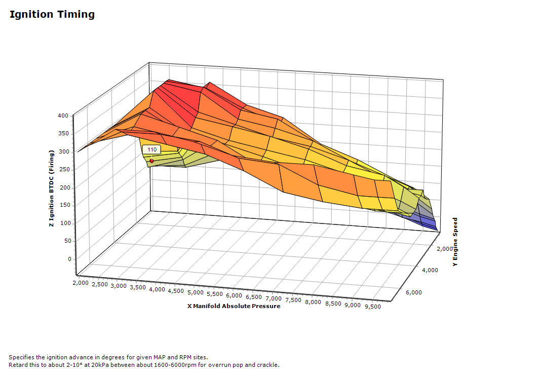
Finally you have
the ability to edit the table definition. Definition
is found on the main menu, on the right-click popup menu on the table grid and
on the drop down menu on the Table
button, and also by double-clicking a table in the list on the left hand side
of the screen. See the notes on Table
Definitions below for more information.
Table Definitions
This is the Table Definition dialog. Definition is found on the main menu,
on the right-click popup menu on the table grid and on the drop down menu on
the Table button, and also by
double-clicking a table in the list on the left hand side of the screen. This
allows you to change the definition of identified, classified tables or add new
definitions for tables not previously identified.
Note that table, scalar and axis class definitions are shared across
all firmware versions and are saved in a single definition file. So if you
change the definition of a table class, you are changing the definition of that
class in all maps and all firmware versions - you are reconfiguring the
application, not modifying the map. If you
change table, scalar or axis definitions you will be prompted whether you wish
to save the changes on exiting the application. The entire definition file is saved on exit, or when clicking the Save button in either the Table Definition or Scalar
Definition dialog.
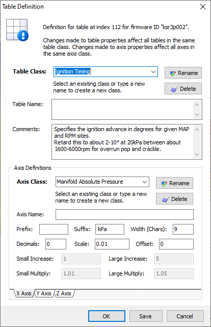
The various fields
which you can edit in this dialog are as follows:
- Table
Class - This allows you to link the table
to an existing class. There will only be one table of each class in a map,
but for example if you encounter a new firmware version and the
application is unable to identify all of the table classes automatically,
you may need to manually link a table to a class. To link a table to an
existing class, you can select the class from the dropdown. To define a
brand new class, simply enter a new class name.
- Table
Class Rename - This button
allows you to rename an existing table class. If you simply type a new
name into the box, this will just create new class for the current table.
If you want to rename an existing class with all tables in the definition
file remaining linked to the new class name, click the Rename button and enter the new
name for the table class.
- Table
Class Delete - This button
allows you to delete a table class. This deletes the table class entirely
from the definition file, so any tables linked to this class will become
unclassified.
- Table
Name - This allows you to enter a longer
name for a table if required. The table name is used in the list of tables
and as the title for the table chart. If left blank, the table class is
used instead. The table name can be multi-line, in which case multiple
lines will be displayed in the title for the table chart but the name is
formatted as a single line when used in the list of tables (the table
class is always a single line).
- Comments
- This allows you to enter detailed
comments relating to the table. These comments are displayed as a footnote
on the table chart. The comments can be multi-line.
- Axis
Class - For each of the X, Y and Z axes
(click through the tabs at the bottom of the dialog to select an axis), this allows you select the axis class to be used. For
2D tables, this will be disabled for either the X axis or the Y axis
(depending on the table structure in the ECU, in every case I’ve seen it
has always been the Y axis which is not used in a 2D table). Many tables
in any map may have axes liked to the same axis class.
- Axis
Class Rename - This button
allows you to rename an existing axis class. If you simply type a new name
into the box, this will just create new class for the current axis. If you
want to rename an existing class with all axes in the definition file
remaining linked to the new class name, click the Rename button and enter the new name for the axis class.
- Axis
Class Delete - This button
allows you to delete an axis class. This deletes the axis class entirely
from the definition file, so any axes linked to this class will become
unclassified.
- Axis
Name - This allows you to enter a longer
name for an axis if required. The axis name is used to label the axis in
the table chart. If left blank, the axis class is used instead. Unlike the
table name, the axis name must be a single line of text.
- Prefix
- This is the prefix displayed
before numbers when formatting for display. It is used in both the table
grid and on chart axes. Note that the main body cells of a table are
linked to the Z axis, so the formatting applied to the Z axis applies to
these cells.
- Suffix
- This is the suffix displayed after
numbers when formatting for display. It is used in both the table grid and
on chart axes. Note that the main body cells of a table are linked to the
Z axis, so the formatting applied to the Z axis applies to these cells.
- Width
(Chars) - This is the nominal display width
required in characters. It is used when determining the column widths in
the table grid. The width of a column will be the largest of i) a default
minimum width, ii) the width defined the axis displayed across the top
(either X or Y) and iii) the width defined for the Z axis.
- Decimals
- This is the number of decimals to
be used when displaying numbers associated with the axis. It is used in
both the table grid and on chart axes. Note that the main body cells of a
table are linked to the Z axis, so the formatting applied to the Z axis
applies to these cells.
- Scale
& Offset - These
together determine the way in which the 16-bit signed integer values
stored in the table memory are scaled to provide meaningful number for
display. For example the Inlet Air
Temperature axis class has a suffix of "°C", a scale of 0.1
and an offset of -273.2. This is because temperatures are stored
internally in tenths of a degree Kelvin and I wanted to display them as
degrees Celsius/Centigrade. So a table value of 2932 is multiplied by 0.1
to give 293.2 and then offset by -273.2 to give 20 - it represents 20°C.
Formatting the axes in this way makes the tables a lot more readable. 20°C
is a lot more meaningful than 2932.
All of the scaling applied to axes and table values works both ways, so for example where a temperature axis has been scaled to read in °C as above, you can edit or paste value in °C and they will automatically be scaled backwards to write the correct values into the underlying table. So you can treat the table as though it actually contains the scaled values and just forget about the scaling once it is set up. - Small
Increase & Large Increase –
These are available for the Z axis only and apply to the main body cells
of the table. The application allows the user to apply simple mathematical
operations to ranges of cells in a table, including increasing and
decreasing by two constant step sizes. These default to 1 and 5 (in
whatever units the table data is displayed), but you can change them for
an axis class if other increments would be more appropriate. See notes on the Value Menu below for
more information.
- Small
Multiply & Large Multiply –
These are available for the Z axis only and apply to the main body cells
of the table. The application allows the user to apply simple mathematical
operations to ranges of cells in a table, including multiplying and
dividing by two constant scale factors. These default to 1.01 (1%
increase) and 1.05 (5% increase), but you can change them for an axis
class if other increments would be more appropriate. See notes on the Value Menu below for more information.
Note that
the main body cells of a table are linked to the Z axis, so the formatting
applied to the Z axis applies to these cells.
Value Menu
The Value menu allows you to manipulate
highlighted ranges of values within a table, using simple mathematical
operations.
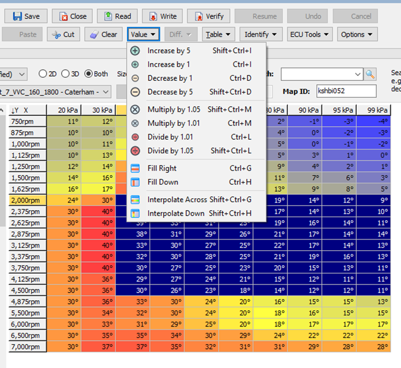
You should
highlight a range of cells to which the operation should be applied in the
table first, then select any of the following
operations through the Value menu:
- Increase
by {Large Number} – This will
increase all of the highlighted numbers by {Large Number} (in whatever
units the table data is displayed). The default is “Increase by 5” but you
can change the value for an axis class if other increments would be more
appropriate. See the notes on Table
Definitions above for more information.
- Increase
by {Small Number} – This will
increase all of the highlighted numbers by {Small Number} (in whatever
units the table data is displayed). The default is “Increase by 1” but you
can change the value for an axis class if other increments would be more
appropriate. See the notes on Table
Definitions above for more information.
- Decrease
by {Small Number} – This will
decrease all of the highlighted numbers by {Small Number} (in whatever
units the table data is displayed). The default is “Decrease by 1” but you
can change the value for an axis class if other increments would be more
appropriate. See the notes on Table
Definitions above for more information.
- Decrease
by {Large Number} – This will
decrease all of the highlighted numbers by {Large Number} (in whatever
units the table data is displayed). The default is “Decrease by 5” but you
can change the value for an axis class if other increments would be more
appropriate. See the notes on Table
Definitions above for more information.
- Multiply
by {Large Number} – This will
multiply all of the highlighted numbers by {Large Number}. The default is
“Multiply by 1.05” (increase by 5%) but you can change the value for an
axis class if other increments would be more appropriate. See the notes on Table Definitions
above for more information.
- Multiply
by {Small Number} – This will
multiply all of the highlighted numbers by {Small Number}. The default is
“Multiply by 1.01” (increase by 1%) but you can change the value for an
axis class if other increments would be more appropriate. See the notes on Table Definitions
above for more information.
- Divide
by {Small Number} – This will
divide all of the highlighted numbers by {Small Number}. The default is “Divide by 1.01” (decrease by 5%) but you can change the
value for an axis class if other increments would be more appropriate. See the notes on Table Definitions
above for more information.
- Divide
by {Large Number} – This will
divide all of the highlighted numbers by {Large Number}. The default is “Divide by 1.05” (decrease by 5%) but you can change the
value for an axis class if other increments would be more appropriate. See the notes on Table Definitions
above for more information.
- Fill
Right – This will copy the numbers in the
leftmost column highlighted across all other columns. This option is only
available when more than one column is highlighted.
- Fill
Right – This will copy the numbers in the
topmost row highlighted across all other rows. This option is only
available when more than one row is highlighted.
- Interpolate
Across – This will leave the numbers in
leftmost and rightmost columns highlighted unchanged, but will fill the
columns between them by interpolating (linearly, in proportion to the axis
values). This allows values to be entered for only a small number of cells
in the table with sensible intermediate values being generated for the
cells between them. This will often be used as a starting point before
making finer adjustments to the intervening cells to generate the shape of
map required. This option is only available when more than two columns are
highlighted.
- Interpolate
Down – This will leave the numbers in
topmost and bottommost rows highlighted unchanged, but will fill the rows
between them by interpolating (linearly, in proportion to the axis
values). This allows values to be entered for only a small number of cells
in the table with sensible intermediate values being generated for the
cells between them. This will often be used as a starting point before
making finer adjustments to the intervening cells to generate the shape of
map required. This option is only available when more than two rows are
highlighted.
The Scalars Tab
The Scalars tab allows you to view and edit
the scalars in the map.

On the left hand
side you will see the list of scalars in the map. This is sorted and
highlighted according to the rules described previously. See the section on Views & Filters for more information. As
scalars are single valued by definition, there is usually no separate grid for
editing scalar values. Instead there is a second column in the list of scalars
allowing you to edit the values. You can edit values in the list and changes
are written back to memory immediately.
In addition, for
scalars which are defined to be in hexadecimal format (see the section on Scalar Definitions below for more information),
you will also see an additional grid showing the equivalent decimal value and
the individual binary bits, as shown below:
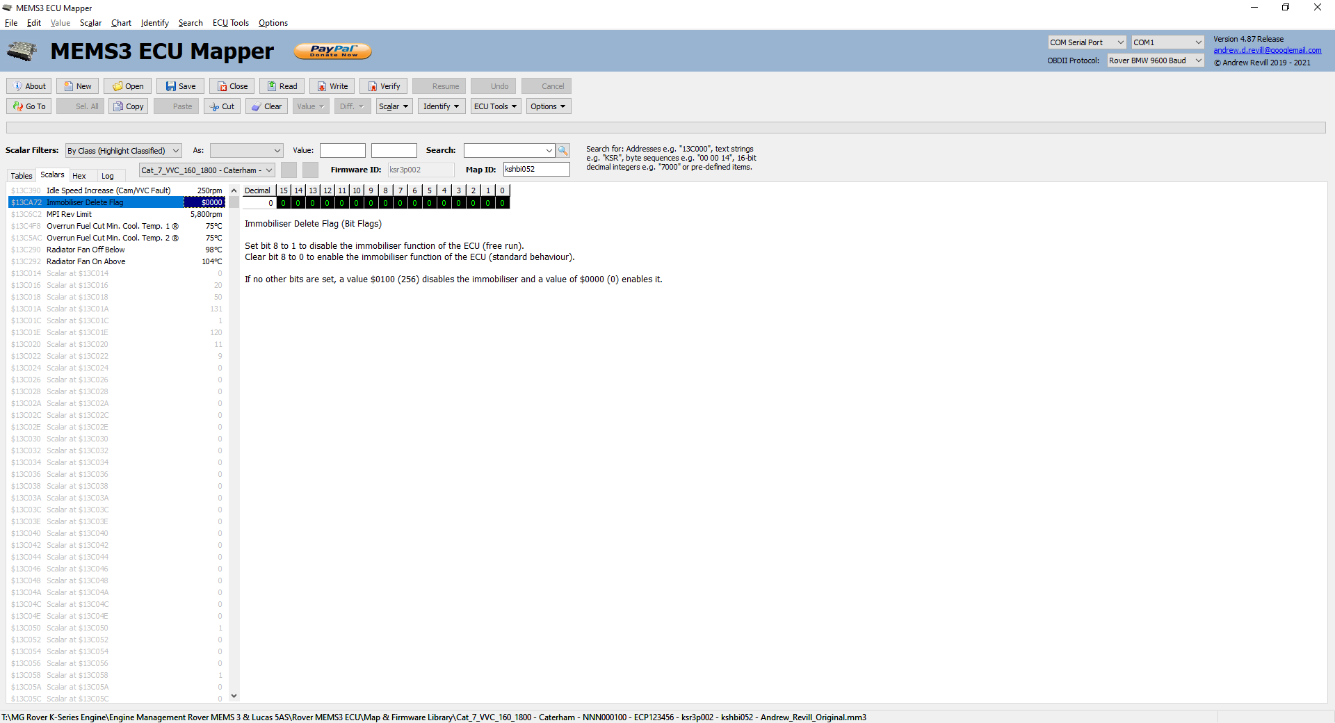
This is useful
where the individual binary bits are used as switches to turn particular
features on and off. For example in the Immobiliser
Delete Flag scalar shown above, bit 8 disables the immobiliser function
when set to a 1 and enables it when cleared to a 0. The function of the other
bits is unknown; in most cases they are all 0 but I have seen ECUs with other
bits set so they must do something, and when updating the Immobiliser Delete Flag you would probably want to leave the other
bits untouched, so a bit-by-bit edit facility comes in handy.
On the right hand
side, below the decimals and binary numbers if displayed, you will see the
comments for the selected scalar.
The Copy, Paste, Cut and Clear buttons work on the selected
scalar. Copy, Paste, Cut and Clear are found on the main menu, on
right click popup menus throughout the application and as buttons on the button
bar.
Just as for tables,
you have the option of displaying Raw
Values. When displaying raw values, none of the axis formatting (scaling,
offsetting or number formatting) is applied. Values are displayed as 16-bit
signed integers, exactly as they appear in the scalar memory. When raw values
are displayed, you also edit and enter numbers in raw format too. For example
here are the identified scalars in a map displayed normally with formatting
(first image) and as raw values (second image). Raw Values is found
on the main menu, on the right-click popup menus on the Scalars tab and on the drop down menu on the Scalar button.
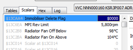

Finally you have
the ability to edit the scalar definition. Definition
is found on the main menu, on the right-click popup menus on the Scalars tab and on the drop down menu
on the Scalar button, and also by double-clicking
a scalar in the list on the left hand side of the screen. See the notes on Scalar Definitions below for more information.
Scalar Definitions
This is the Scalar Definition dialog. Definition is found on the main menu,
on the right-click popup menus on the Scalar
tab and on the drop down menu on the Scalar
button, and also by double-clicking a scalar in the list on the left hand side
of the screen. This allows you to change the definition of identified,
classified scalars or add new definitions for scalars not previously
identified.
Note that table, scalar and axis class definitions are shared across
all firmware versions and are saved in a single definition file. So if you
change the definition of a scalar class, you are changing the definition of
that class in all maps and all firmware versions - you are reconfiguring the
application, not modifying the map. If you
change table, scalar or axis definitions you will be prompted whether you wish
to save the changes on exiting the application. The entire definition file is saved on exit, or when clicking the Save button in either the Table Definition or Scalar
Definition dialog.
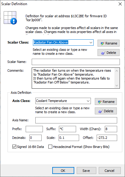
The various fields
which you can edit in this dialog are as follows:
- Scalar
Class - This allows you to link the
scalar to an existing class. There will normally only be one scalar of
each class in a map, but for example if you encounter a new firmware
version and the application is unable to identify all of the scalar
classes automatically, you may need to manually link a scalar to a class.
To link a scalar to an existing class, you can select the class from the
dropdown. To define a brand new class, simply enter a new class name.
- Scalar
Class Rename - This button
allows you to rename an existing scalar class. If you simply type a new
name into the box, this will just create new class for the current scalar.
If you want to rename an existing class with all scalars in the definition
file remaining linked to the new class name, click the Rename button and enter the new
name for the scalar class.
- Scalar
Class Delete - This button
allows you to delete a scalar class. This deletes the scalar class
entirely from the definition file, so any tables linked to this class will
become unclassified.
- Scalar
Name - This allows you to enter a longer
name for a scalar if required. The scalar name is used in the list of
scalars and in the notes displayed on the right hand side of the screen.
If left blank, the scalar class is used instead. Unlike a table name, the
scalar name must be a single line of text.
- Comments
- This allows you to enter detailed
comments relating to the scalar. These comments are displayed in the notes
on the right hand side of the screen. The comments can be multi-line.
- Axis
Class - A scalar is associated with a
single axis class which defines the number formatting, scaling and
offsetting in exactly the same way as for a table. Many scalars in any map
may have axes liked to the same axis class. The axis class definitions are
common to both tables and scalars as for example there are both tables and
scalars which specify Coolant
Temperature values.
- Axis
Class Rename - This button
allows you to rename an existing axis class. If you simply type a new name
into the box, this will just create new class for the current axis. If you
want to rename an existing class with all axes in the definition file
remaining linked to the new class name, click the Rename button and enter the new name for the axis class.
- Axis Class
Delete - This button allows you to delete
an axis class. This deletes the axis class entirely from the definition
file, so any axes linked to this class will become unclassified.
- Axis
Name - This allows you to enter a longer
name for an axis if required. The axis name is appended to the scalar name
in brackets in the notes on the right hand side of the screen. If left
blank, the axis class is used instead. Unlike the table name, the axis
name must be a single line of text.
- Prefix
- This is the prefix displayed
before numbers when formatting for display.
- Suffix
- This is the suffix displayed after
numbers when formatting for display
- Width
(Chars) - This is the nominal display width
required in characters. It is used when determining the column width in the
scalar list. The width of the column displaying scalar values will be the
largest of i) a default minimum width and ii) the largest width defined
for the axis of any classified scalar.
- Decimals
- This is the number of decimals to
be used when displaying numbers associated with the axis.
- Scale
& Offset - These
together determine the way in which the 16-bit signed integer values
stored in the table memory are scaled to provide meaningful number for
display. For example the "Inlet Air Temperature" axis class has
a suffix of "°C", a scale of 0.1 and an offset of -273.2. This
is because temperatures are stored internally in tenths of a degree Kelvin
and I wanted to display them as degrees Celsius/Centigrade. So a scalar
value of 2932 is multiplied by 0.1 to give 293.2 and then offset by -273.2
to give 20 - it represents 20°C. Formatting the axes in this way makes the
scalars a lot more readable. 20°C is a lot more meaningful than 2932.
All of the scaling applied to scalar values works both ways, so for example where a temperature scalar has been scaled to read in °C as above, you can edit or paste value in °C and they will automatically be scaled backwards to write the correct values into the underlying scalar. So you can treat the scalar as though it actually contains the scaled values and just forget about the scaling once it is set up.
Tables Identified
I will now go
through the various tables which I have been able to identify in the maps of
various MPI and VVC ECUs with some comments on exactly how they appear to work
and how I went about identifying them and proving their functions where
appropriate.
- Accel.
Enrich. (Temp. & RPM) ® - This table controls the acceleration
enrichment feature. I’m not sure what the numbers on the Z axis actually
mean, but the larger the number the greater the acceleration enrichment
effect so they can be adjusted on the basis of “a bit more” or “a bit
less” as required. The overall magnitude of the acceleration enrichment
effect is specified by coolant temperature and RPM.
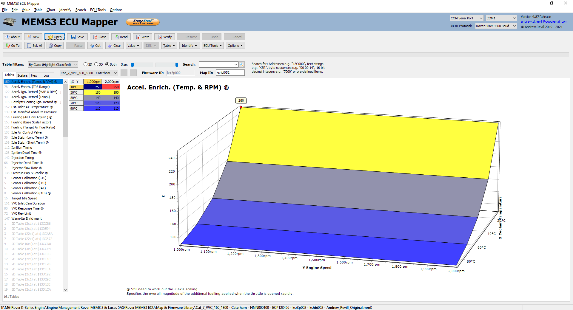
Acceleration enrichment adds in multiple injection events per engine cycle to enrich the mixture on rapid transient throttle opening. The oscilloscope trace below shows the fuel injector drive pulses (with the engine and ECU “running” using a fake crank and cam signal generator which allowed me to fool the ECU into thinking it was running the injectors and ignition without the engine actually turning, which meant that I could then swing the throttle without over-revving the engine). This trace shows the waveform at No 1 injector with a steady open throttle:
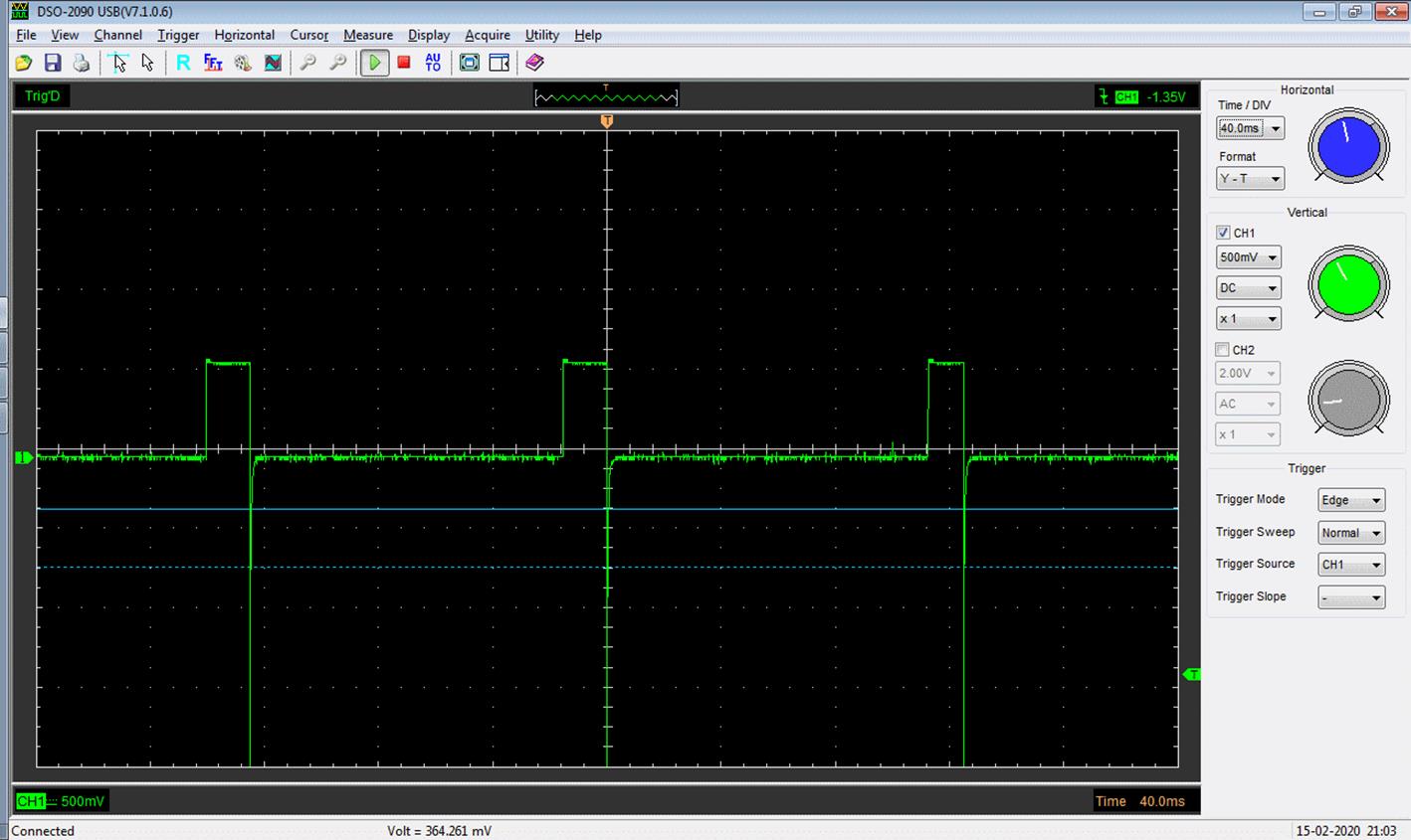
The trace below shows the same situation but during a medium rate opening of the throttle:
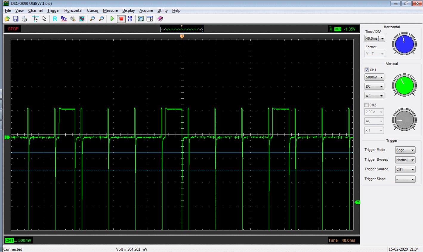
The trace below shows the same situation but during a more rapid rate opening of the throttle:

You can see that four additional injection events are added per cycle, in addition to the normal injection pulse, and the more rapidly the throttle is opened, the wider these pulses are and the greater the degree of enrichment. The additional pulses are basically batch-mode fired in parallel with the sequential normal injection pulses.
NB: This table is marked with “®” for “Research” as I still need to track down the precise meaning of the numbers on the Z axis. - Accel.
Enrich. (TPS Range) - This table
also controls the acceleration enrichment feature described above. The
acceleration enrichment is only applied over the lower portion of the TPS
scale. The maximum percentage throttle at which it operates is defined by
this table.
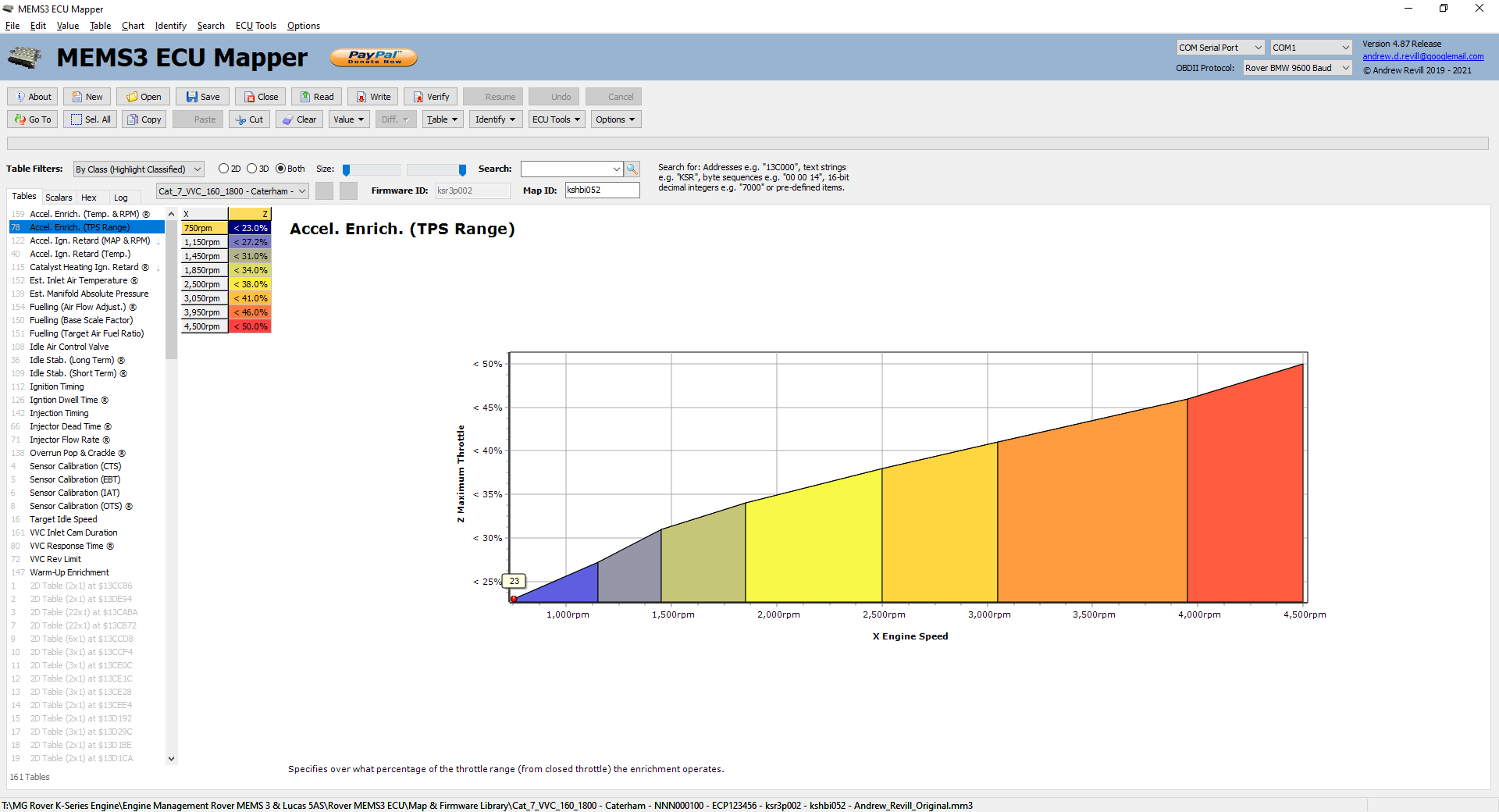
- Accel.
Ign. Retard (MAP & RPM) -
This table controls the acceleration retard feature. This feature retards
the ignition timing for a period of time on rapid throttle opening. The
overall magnitude of the acceleration retard effect is specified by
coolant MAP and RPM.
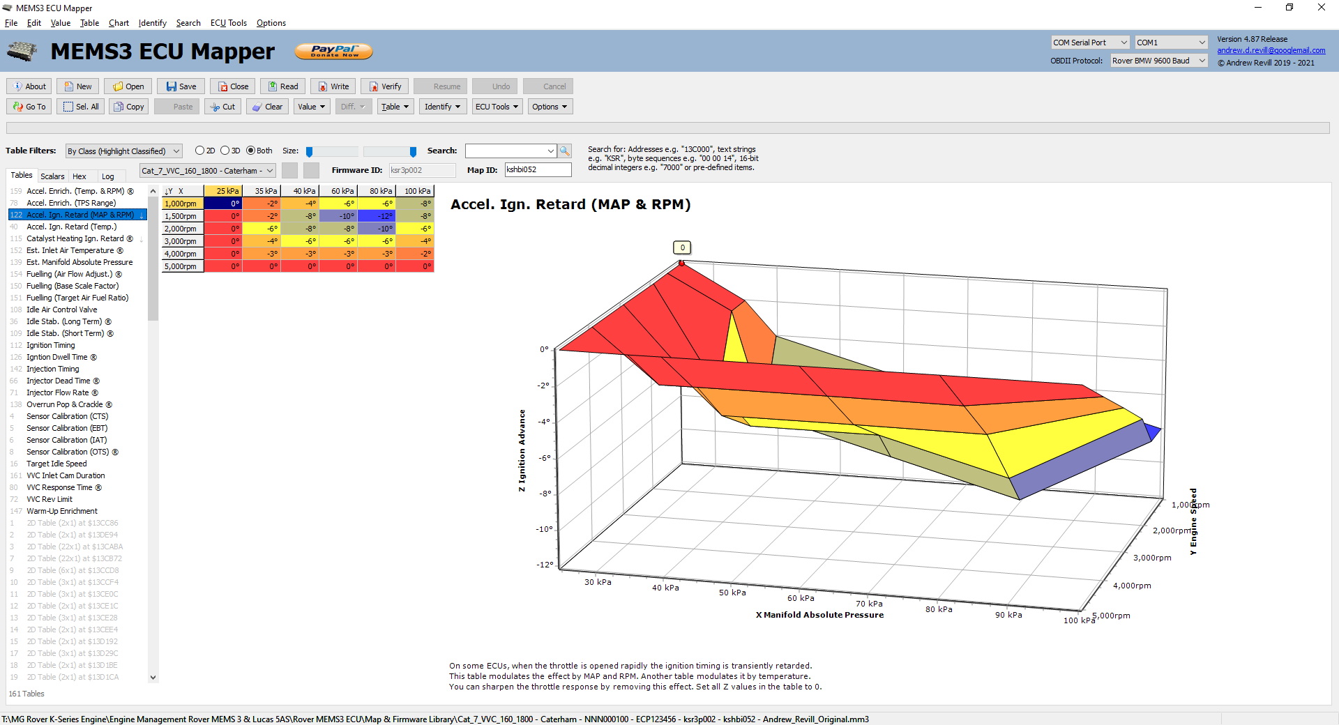
NB: The chart Z axis is correctly labelled as Ignition Advance; the numbers in this table are negative, and a negative advance is a retard.
The primary purpose of this effect seems to be to soften the throttle response. When you open the throttle rapidly, the ignition timing is initially retarded by quite a large crank angle to damp down the performance; over a period of a second or two, it then slowly advances back to the static value specified in the Base Ignition Timing table, bringing the increased performance in gradually.
The oscilloscope trace below shows the ignition waveform, triggered off the cam sensor waveform to get a fixed timing. This is with the throttle in a steady wide open position:
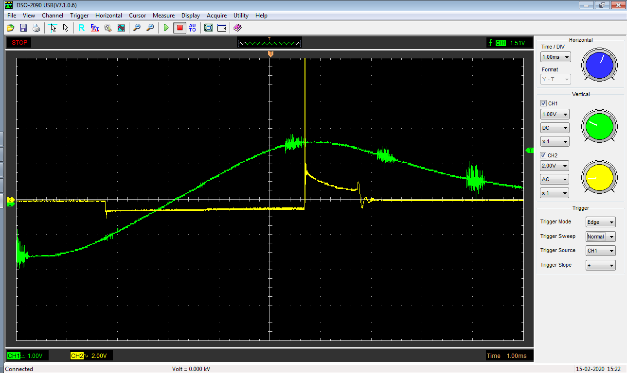
And this trace shows the same situation but during rapid opening of the throttle:
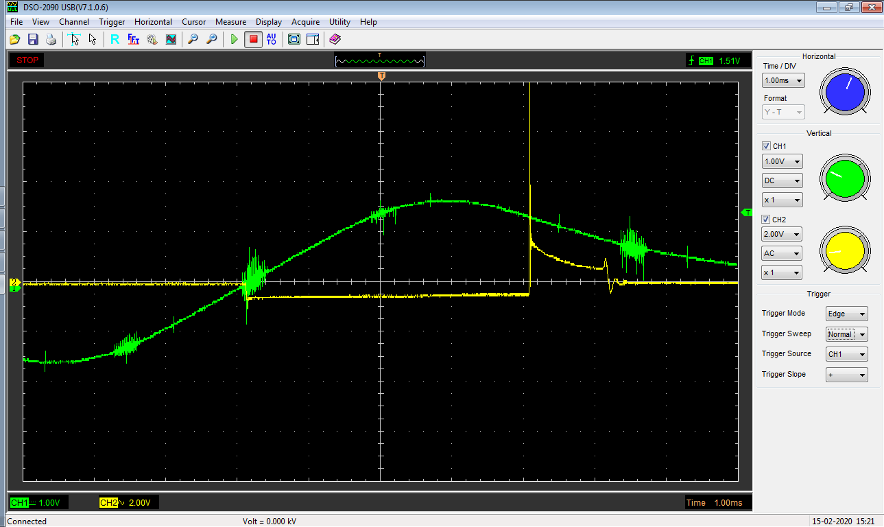
You can see here that the ignition is retarded significantly from its steady state timing.
Hint: Removal of this effect is one of the main ways in which remaps sharpen up the feel of the throttle response. It makes a huge difference to the feel of the car taking this effect out, even if you do nothing else. Taking out the effect is easy, just change all of the numbers in this table to 0. The easiest way to do this in the application is to click Select All, then Clear.
This will not affect overall ignition timing and shouldn’t have any negative effects, so it’s a quick win without needing any dyno validation. - Accel.
Ign. Retard (Temp.) - This table
also controls the acceleration retard feature described above. It modulates
the effect according to coolant temperature.
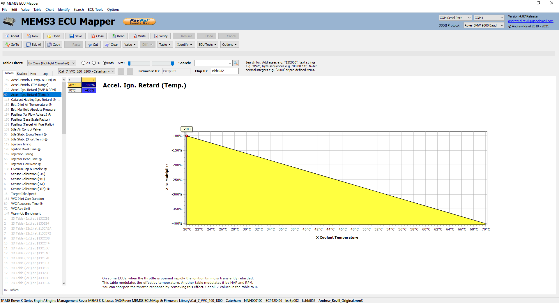
I think the numbers from the two tables are effectively multiplied to get an overall magnitude for the effect. Setting either one of these tables to 0 throughout seems to take the effect out. For good measure I’ve cleared both tables on my ECU.
Hint: Removal of this effect is one of the main ways in which remaps sharpen up the feel of the throttle response. It makes a huge difference to the feel of the car taking this effect out, even if you do nothing else. Taking out the effect is easy, just change all of the numbers in this table to 0. The easiest way to do this in the application is to click Select All, then Clear.
This will not affect overall ignition timing and shouldn’t have any negative effects, so it’s a quick win without needing any dyno validation. - Catalyst
Heating Ignition Retard ® -
This table appears to define an ignition retard which is applied at
mid-range RPM and MAPs for a short period after first starting the engine
only.
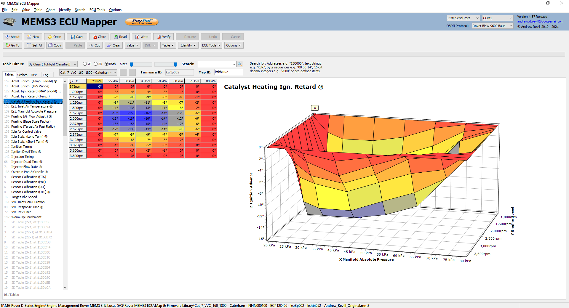
NB: The chart Z axis is correctly labelled as Ignition Advance; the numbers in this table are negative, and a negative advance is a retard.
This may be for driveability but as it seems to apply for a very short time and is not apparently driven by coolant temperature, my best understanding of this is that it is for the purposes of heating the catalytic converter rapidly. Retarded ignition timing causes hotter exhaust gas temperatures and so this retard effects dumps a large amount of heat into the exhaust system when the engine is started. Certainly when I was first digging into this effect and extended it down to idle RPMs the exhaust headers seemed to get very hot very quickly.
I still need to work out exactly constitutes “a short period”. If I start the engine cold and turn the throttle screw in to bring it off idle to a steady 2000rpm, the ignition retard defined by this table seems to take effect around 7-8 seconds after starting and persist for a little over 2 minutes. If on the other hand I try to maintain the revs by hand on the throttle quadrant and end up revving it a bit more, the effect seems to terminate after around 1 minute 40 seconds. So it may be defined in terms of a count of engine revolutions rather than a fixed time.
There is also some complex interplay between the main ignition timing table, this table and the table which I have provisionally name “Overrun Pop & Crackle Effects”. This is clearly not an appropriate final name for this mysterious table, but until I have managed to fully understand I’ve just named it after the effect it seems to be most affecting. It appears that making the changes I suggested to the Overrun Pop & Crackle Effects table also largely disables this ignition retard effect, so that table seems to be controlling the transition between the starting settings and normal running setting in some way.
Hint: On our cars you can turn this effect off by clearing the whole table to 0. Until I fully understand the Overrun Pop & Crackle Effects table, this is probably advisable to ensure that the changes made in that table don’t cause this effect to be applied inappropriately.
NB: This table is marked with “®” for “Research” as I still need to fully understand it. - Est.
Inlet Air Temperature. ® - This table provides estimated values for
the inlet air temperature.
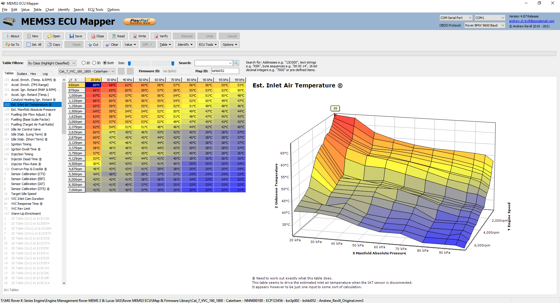
The values in this table are not used directly as the estimated inlet air temperature values when the inlet air temperature sensor is disconnected or has failed, but they do heavily drive the calculation. More work is required to fully understand the calculations being performed here.
NB: This table is marked with “®” for “Research” as I still need to fully understand it. - Est.
Manifold Absolute Pressure -
This table provides estimated values used for the MAP sensor when the ECU
decides that it has failed.
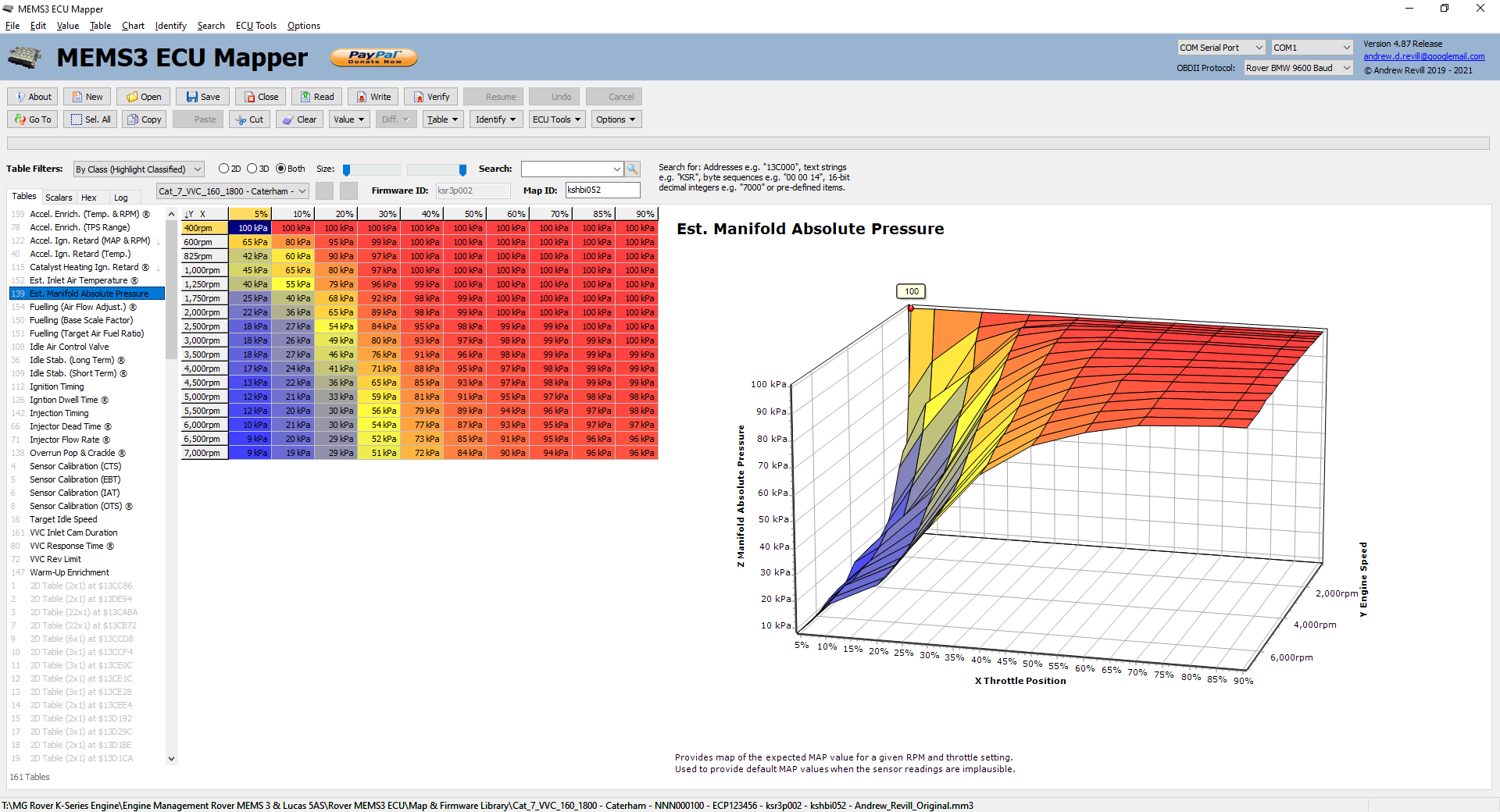
If you unplug the MAP sensor while the engine is idling it will stumble horribly for a second or so, then start to run apparently normally.
For a brief moment the engine will be running on MAP values which do not correspond to the RPM and TPS values and will be effectively “off piste” as far as the map is concerned. However it will rapidly realise that MAP values it is receiving do not make sense and switch over to using values looked up from this table.
This may be of little practical value and purely academic interest but here’s a thought …
I wonder, if this table was mapped properly … would it be good enough to run an engine using TPS as the primary load sensor rather than MAP? Probably a long shot, but if so it could be used to map the ECU for throttle body engines without having to worry about pulse damping to get a sensibly smooth MAP signal without a plenum. I’d be interested to see how well my car drives with the MAP sensor unplugged as that would give a good indication of whether it is likely to be possible. Even if it runs a lower rev limit due to the fault condition, that’s likely to be scalar value somewhere in the ECU. Just a thought for a future project! - Fuelling
- There are three main tables
controlling the fuelling. Before looking at each table in turn, it’s
probably best if I go through what I’ve worked out about how these ECUs
manage fuelling.
They seem to work on a variant of the volumetric efficiency model. Rather than having a table which specifies how much fuel to inject at given load and speed sites, they use tables to model the air flow under different conditions and another table which specifies the target AFRs that it wishes to achieve. It then divides the air flow numbers by the target AFR numbers to get the fuel requirement.
My understanding is that when mapping an engine from scratch using a volumetric efficiency model, ideally you firstly set the target AFRs then with lambda adaptations disabled you adjust the air flow model until you hit the target AFRs everywhere; you then have the air flow model correctly representing the air flow in the engine.
Once mapped, you then enable lambda adaptations again and the ECU will use closed loop lambda control anywhere where the target AFR is exactly stoichiometric (14.7:1) and will run open loop elsewhere.
So on this basis, I was expecting to find at least two tables, one giving volumetric efficiency (effectively mass air flow as a percentage of the ideal mass air flow assuming the engine consumed its full cubic capacity of air at atmospheric pressure per engine cycle) and one giving target AFRs. However, I wasn’t able to find anything which looked exactly like a volumetric efficiency table. What I did find (in my VVC 160 ECU) was the following:
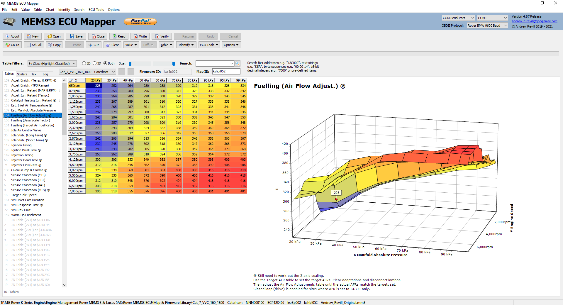
Superficially this has the form of a volumetric efficiency table but it is misleading as the axis scaling on the vertical axis doesn’t go to 0; the table values don’t drop off anywhere near as far as would be expected at very low MAP values where the engine is being strangled by a closed throttle.
So I then did some analysis to try to work out what was going. I noticed that if you rotate the 3D chart to view it end-on, with RPM across, you see this:
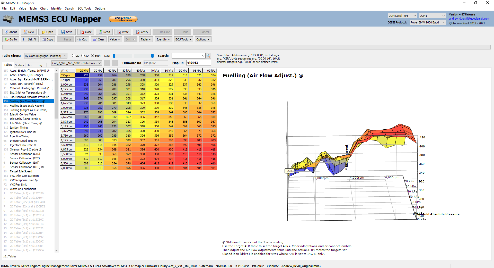
Now there should be a very strong correspondence between the air flow model and engine torque, and I had some dyno results for my engine so I took the numbers in the right hand column (a reasonable enough approximation to full throttle as was used on the dyno for these purposes) and plotted them against the torque numbers from my dyno result in Excel. I scaled both sets of numbers as percentages of their averages to make the scales comparable. This is what I got:
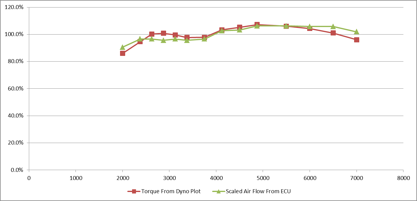
The correlation is striking and clear, so I was sure I was on the right track. I did quite a bit of experimentation by adjusting values in the table and observing the impact on the fuel trims applied by the ECU as it tried to correct the lambda (under closed loop conditions). This really confirmed that this table was directly controlling the fuelling and led me to the following conclusions: - This
table is air flow. However there is another factor which is multiplied in
to give actual volumetric efficiency which would result in the value
dropping off at lower MAPs. My tentative guess; this table is effectively
VOLUME AIR FLOW not MASS AIR FLOW and the ECU multiplies it by air
density, which it calculates from MAP and IAT.
- Where you already have a map which is not
too far wrong (i.e. working from a stock MG Rover map), you don’t really
need to know the exact calculation above, as you will only be interested
in correcting the fuelling to account for changes in air flow due to head
work, cam changes etc. So you will be working on the basis of “a little
bit more” or “a little bit less” until you get the AFRs you want - you
don’t need to know exactly what the numbers equate to, you just need to
be able to increase and decrease them a bit to tune the map.
- In
Conclusion: You can regard this table as being the correct place to make
incremental fuelling changes. Increasing or decreasing the numbers at any
given site increases or decreases the fuelling roughly proportionally.
After all of the
head flow work, exhaust cam changes and cam timing changes I have done to my
engine, when I had it on the rolling road we found that the mixture was going a
too lean for comfort and a couple of points in the rev range at WOT. Now I can
see why; if I’ve increased the actual air flow through modifications but not
increased the numbers in the air flow table, at any given RPM and MAP the ECU
is likely to underestimating the fuel requirement. For the time being I fixed
this by slightly increasing the fuel pressure, but now I should be able to
adjust the fuelling just at the point where an increase is required rather than
applying a blanket 5% increase.
So now for the
three tables I actually found…
- Fuelling
(Target Air Fuel Ratio) - This
specifies the target AFR any given RPM and MAP.
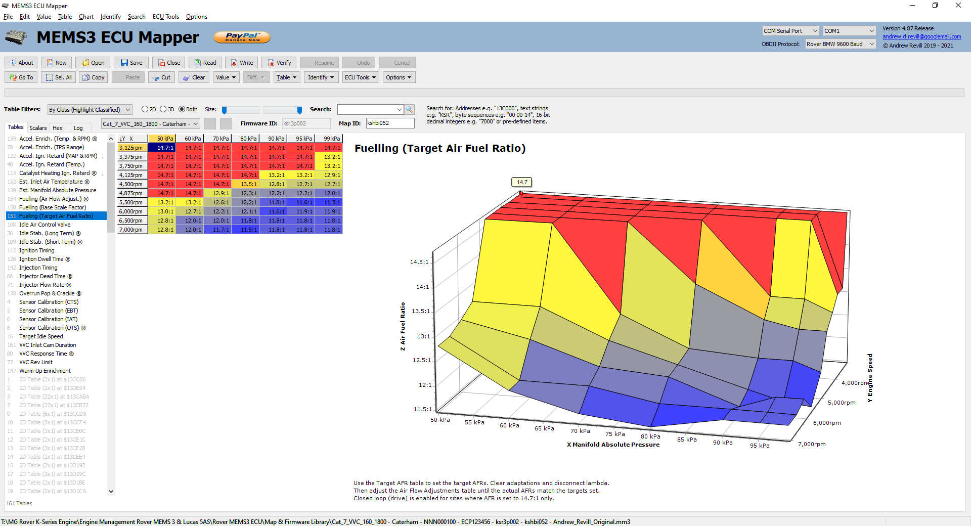
You can see that the target AFR is 14.7:1 at lower RPMs and MAPs and the mixture then goes richer at higher loads and speeds. The ECU will use the lambda sensor in closed loop mode to adapt the basic map and trim to the correct AFR in all sites where the target AFR is EXACTLY 14:7 in this table and will run pen loop elsewhere.
Note that the underlying raw table value which codes for closed loop operation is 290. You will see this if you select Raw Values. I have defined a scale factor of 0.0506897 to scale this down to 14.7. I know the correct stoichiometric ratio is closer to 14.68:1 which would give a scale factor of 0.0506206, but I wanted to display to one decimal place and I wanted to guarantee that keying in a value of 14:7 to one decimal place would store exactly 290 in the underlying table to ensure that it target closed loop operation, so for this reason I used the correct scale factor for 14:7. The difference is only 0.13%.
You can effectively disable lambda control at any site by changing the Target Air Fuel Ratio from 290 to say 289 in this table. - Fuelling
(Air Flow Model) ® - This is the air flow model discussed in
some detail in the Fuelling section above.
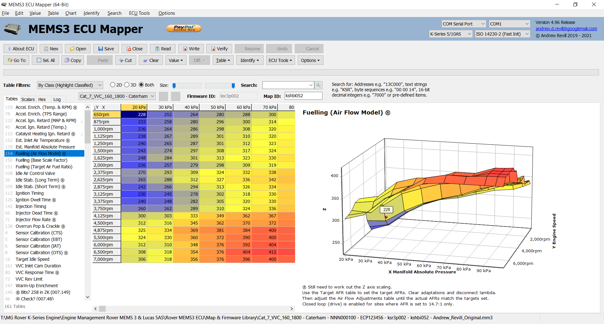
NB: This table is marked with “®” for “Research” as I still need to track down the precise meaning of the numbers on the Z axis. - Fuelling
(Base Scale Factor) - This
appears to be an overall scale factor applied to the base fuelling.

In most cases this is a flat value of 100%, although in some maps from real ECUs I’ve seen non-flat adjustments applied here, although why these would be applied separately to the main fuelling table I am not sure. I guess if for some reason the injector flow rate is found to vary by MAP or IAT then the correct way to account for this is through this table rather than by fixing up the air flow model. Here’s a real example of where this table contained correction in an MPI ECU:
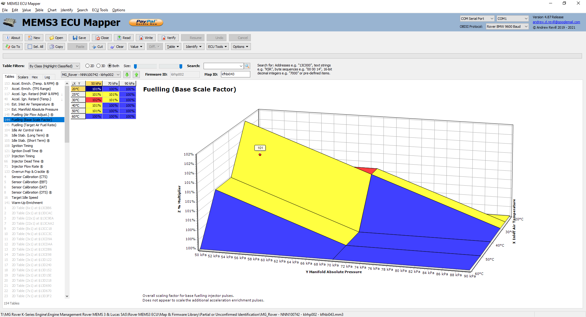
The corrections are only small, up to 2%.
I guess you could use this to rescale the fuelling if you used injectors with a different flow rate. Oddly though, from my testing this only appears to scale the base fuelling and not the additional acceleration enrichment pulses, so if you used injectors with a markedly different flow rate you may need to adjust the acceleration enrichment (and possibly warm-up enrichment) separately. - Idle
Air Control Valve - This table
controls the default position adopted by the idle air control valve.
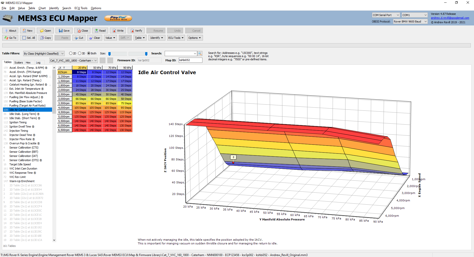
The idle air control valve is clearly used for a lot more than just controlling the idle!
This table seems to control what position the idle air control valve moves to when it is not actively managing the idle. It appears to have two major impacts: - It manages the orderly return to idle.
Increasing values in the table can increase the time taken to return to
idle. By tapering the values down towards idle speed, this effectively
provides a little bit of throttle as the revs decay and softens the
return to idle, allowing the engine to settle to settle progressively to
idle speed without hovering at high RPM or stalling.
- It manages the vacuum level if you suddenly
lift off at high RPM. If you reduce the values in this table, the idle
air control valve will be in a more closed position at higher RPM. This
means that if you suddenly lift off the throttle, the MAP will fall a lot
further (higher manifold vacuum) leading to more aggressive engine
braking. By reducing the numbers here you can induce some of the feel of
a lightened flywheel, with the revs dropping off more rapidly,
however this is at the expense of higher vacuum levels which can draw oil
past the valve stem oil seals and lead to higher oil consumption
especially in older engines. Having said that, engines running throttle
bodies have NO idle air control valve - adjustment of the idle stop screw
on these engines is almost the same as setting the idle air control valve
it its minimum position at all times, leading to maximum engine braking
and maximally rapid rev decay and this doesn’t seem to cause too many
problems.
- Idle
Stabilisation (Long Term) ® - This table controls long term idle
stabilisation through the use of the idle air control valve (IACV).
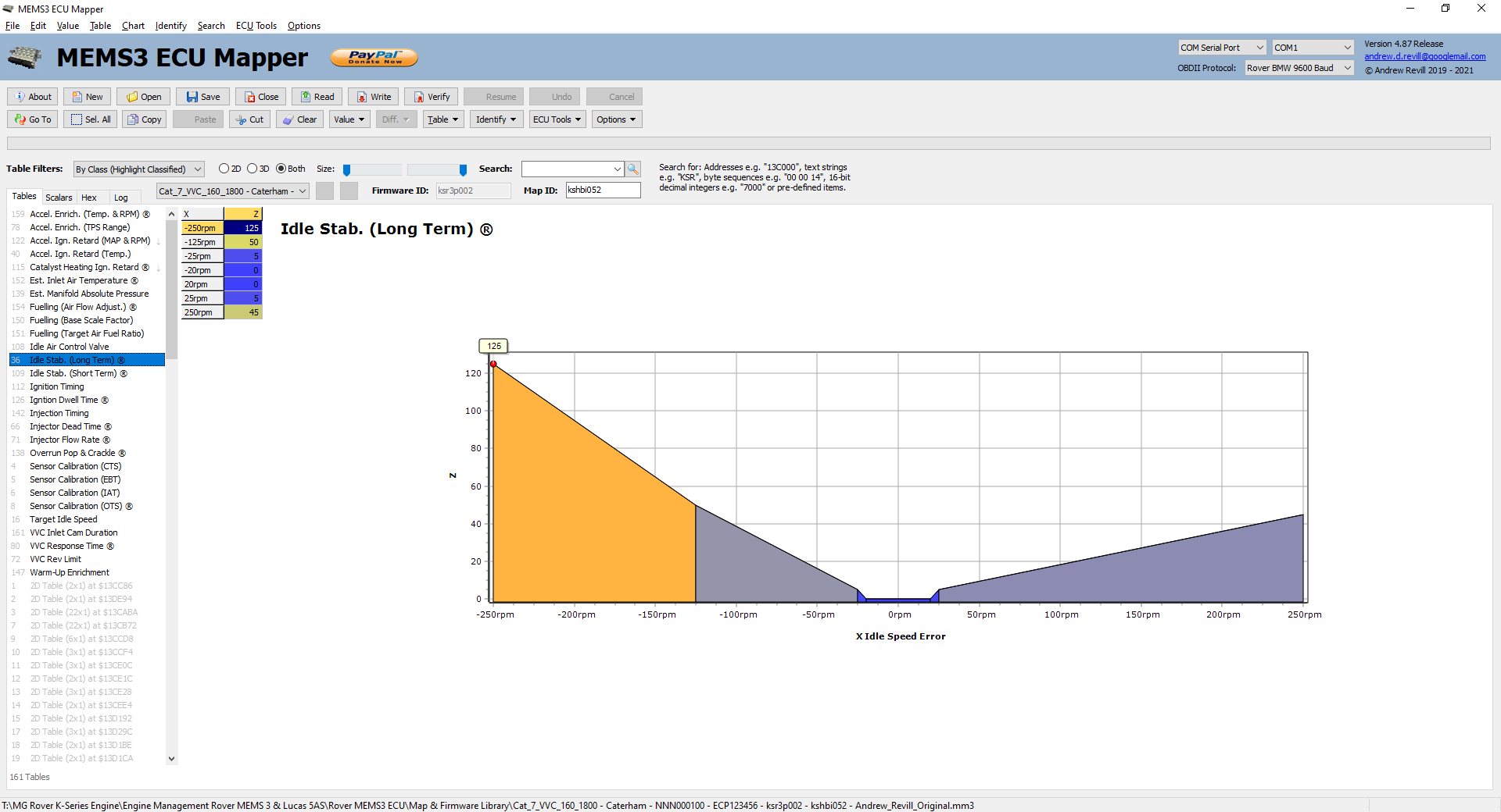
This table is used to manage long term adjustments to the idle speed when it goes beyond the short term adjustment range using ignition timing provided by the Idle Stabilisation (Short Term) table. There is a small error band around zero with no response within which it would rely on the short term trim through ignition timing, with corrections either side, and a more aggressive response to lower than desirable idle speed to prevent stalls.
It surprises me a bit that the Z axis values are positive on both sides of the zero band as I would have expected them to be represented as positive and negative corrections, but the ECU must apply the sign of the actual error in some way on top of the values provided by this table. It is possible that the correction factor provided by this table is a multiplier, which is multiplied by the actual error or something similar, in which case the sign would be correct.
In order to confirm that this table was providing the long term idle stabilisation I performed some experiments:
With the Idle Stabilisation (Short Term) table zeroed out the idle became unstable, hunting up and down over a period of a few seconds as the engine is forced to use the long term corrections using the relative slow responding idle air control valve only. When I further zeroed out this table the idle stopped hunting but tended to drift away from the normal value with temperature or load changes as the ECU was making no attempt to correct it using either ignition timing or IACV inputs.
If I doubled the response to low idle RPMs and put zero response for high idle RPMs, the engine initially started and ran normally, but the first time the RPM dipped significantly below the target idle speed the IACV overreacted, kicking the idle speed too high. It then just sat there with no desire to come back down again.
If I double the response to high idle RPMs and put zero response for low idle RPMs, the engine again initially started and ran normally, but the first time the RPM rose significantly above the target idle speed the IACV again overreacted, this time dropping the speed too low. The ECU again failed to correct this and just allowed the engine to stall.
I still need to work out exactly what the Z axis represents on this table. It will be something like "rate of change of IACV position", but exactly how it is defined may take some working out. The consistent positive sign gives me a clue that it may be multiplied by the error value.
NB: This table is marked with “®” for “Research” as I still need to track down exactly what the Z axis represents. - Idle
Stabilisation (Short Term) -
This table controls short term idle stabilisation through ignition timing.
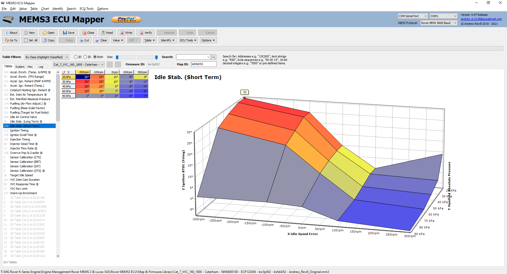
This table quite simply provides the ignition timing to be used when in idle strategy as a function of the MAP and the error between the actual engine RPM and the desired RPM (as mapped by the Target Idle Speed table etc.). If cleared to zero the idle becomes unstable, hunting up and down over a period of a few seconds as the engine is forced to use the long term corrections using the relative slow responding idle air control valve only.
So when the actual idle speed falls below the desired idle speed, this table advances the ignition to increase power and raise the idle speed. When the actual idle speed rises above the desired idle speed, this table retards the ignition to decrease power and lower the idle speed.
The Y axis appears to be MAP. It surprises me a bit that idle control settings are mapped right up to 90kPa but there's very little resolution at the higher end of the MAP scale and the effect tails off towards a flatter ignition timing, so this is possibly just to give it some settings to use under transient unusual conditions (brake servo operation maybe?). - Ignition
Timing - This is the main ignition timing
table. It specifies the static ignition timing (excluding dynamic effects
such as the acceleration retard described above) in crank degrees BTDC on
the firing stroke.

The ignition timing in MG Rover maps tends to be rather conservative and there is considerable scope for advancing the ignition timing to increase performance, although this needs to be done with care and probably by validating the results on a dyno to avoid damaging the engine through detonation if the ignition is advanced too far.
Hint: This table is one of two or three where remaps generate the “pop and crackle” effects on the overrun, which are very easy to map in yourself. This is done through aggressively retarded ignition timing at high vacuum levels (very low MAP values) at intermediate RPMs. There’s nothing subtle about it - you just stick in a big retard number in the left hand column, typically between about 1600rpm and 6000rpm like this:
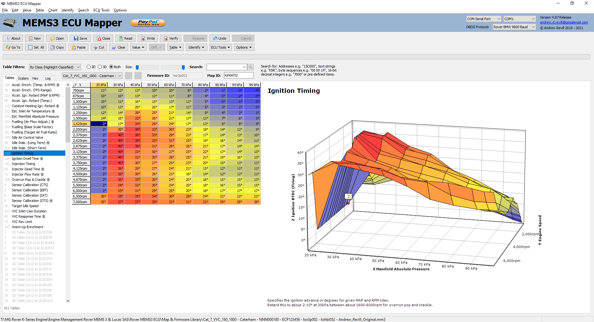
That’s all there is to it as far as ignition timing is concerned, but see the sections on Overrun Pop & Crackle and Catalyst Heating Retard below. I’ve seen number ranging from 10° (giving an increased burble) through 5° (giving noticeably more pop and crackle) down to 2° (giving a much more aggressive effect). Now that you can safely remap your own ECU at will, you can play and try out different numbers to see what you like.
One thing I will say though after playing with this on my car is that the pop and crackle effects definitely do have an effect on the smoothness of the lift-off and tend to introduce a bit of ragged step in the transition between drive and idle strategies. The more aggressive you go, the more ragged it feels. It’s not really problem so long as you don’t go too far, I’ve been driving my car around with 10° and later 5° maps for years before I knew any of this and it was fine, but when I tried restoring the ignition timing from a stock map (just in the first column - I noticed that my remapped ECU had stock values everywhere in the second column and elsewhere in the first column and only had non-stock numbers at higher MAP values) it not only took out the pop and crackle but also made it noticeably smoother to drive at lower throttle settings.
One thing you can try to limit the impact of this is to tighten it up to VERY low MAPs by editing the 25kPa axis value to 23kPa. As it’s all at low load you’re very unlikely to do any damage so you can play around finding out what settings you like best. - Overrun
Pop & Crackle ® - This
table seems to markedly affect the overrun once the ECU is off its
starting map.
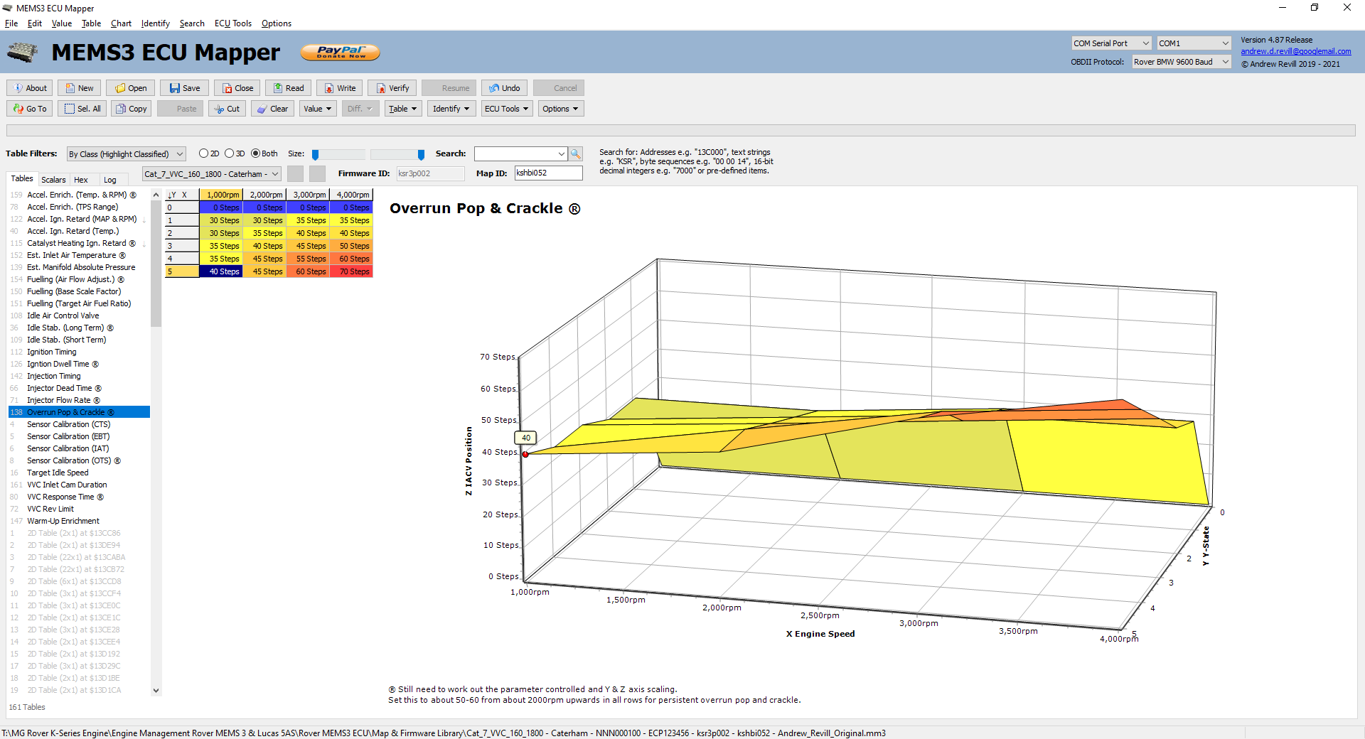
If you just make the ignition timing changes in the Ignition Timing table described above, you will find that the car produces a lot of pops and crackles when first started (both hot and cold) but that these effects stop abruptly after a short period of running.
Unfortunately due to current conditions I have been unable to take the car out on the road to analyse exactly what this table is controlling, and it is impossible to hold sustained overrun conditions with the car stationary in the garage. As soon as conditions allow I will get to the bottom of this table and write it up more fully.
In the meantime, in order to produce sustained pop and crackle effects, I suggest entering numbers of the order of 50-60 in all rows except the last, and all columns except the lowest RPM. Something like this should work nicely:
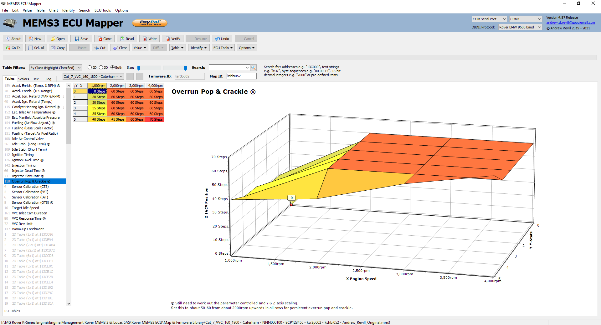
You will find the form of this table varies enormously between different stock MG Rover maps, but the advice given above on modifying the values seems to work well in most cases.
NB: This table is marked with “®” for “Research” as I still need to track down precisely what it controls. Currently unsure of the meaning of the Y and Z axis values. - Ignition
Dwell Time ® - This table determines the ignition dwell
time for a given RPM and battery voltage.
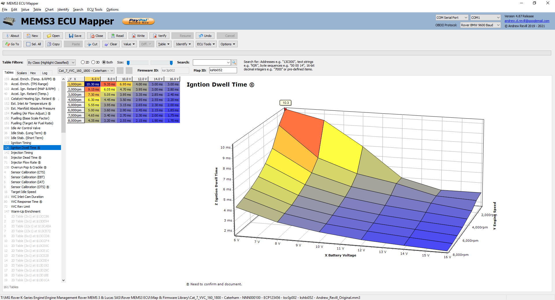
The ignition dwell time is the time (here in milliseconds) for which the ignition coils are turned on and “charged” with current, before being turned off and releasing all their stored energy as a high voltage spark.
The ignition coils are inductors and so when a steady voltage is applied across them, the current through them rises linearly. They also have some resistance; you can think of the resistance element as being a resistor in series with the pure ideal inductance of the coil. As the current rises, Ohm’s law tells us that the voltage across the resistance will rise, leaving less voltage across the inductance and therefore the rate of rise of the current ramp tails off. At some point the coil will saturate; at this point the voltage dropped across the resistance matches the applied voltage and so there is zero voltage remaining to drive the current ramp, and the current remains constant. In this condition, all of the power being delivered into the coil is being dissipated as heat and no more energy is being stored in the coil in a form which contributes to the spark.
Setting a dwell time which is too high will therefore just lead to excess heat in the coil packs and consequent damage. Setting a dwell time which is too low will lead to less current in the coil pack at the point where the spark is generated, therefore less energy in the spark. The spark will burn for a shorter time and at high loads ignition misfires may occur. At higher RPMs there is less time between firing events and so the dwell time has to be restricted. As there are more firing events per second the amount of heat energy dissipated in the coil packs will also increase and the dwell time may have to be limited to avoid coil damage through overheating.
The most obvious feature of this table though is the fact that the dwell time rises as the battery supply voltage falls. As the voltage falls, the rate at which the primary current builds up falls in proportion, and therefore a long dwell time is required in order to ramp the current up to the required value to generate an optimal spark.
As the timing of the ignition events (which occur at the point when the coil is turned off at the end of the dwell time) is a critical parameter for engine performance, the ECU cannot simply turn the coil on and then turn it off when the current reaches the desired level. It must know fairly accurately in advance how long it will take the primary current to ramp up to the desired level, and then it can begin the dwell period an appropriate time before the desired time of the ignition event. This table gives the ECU that critical information.
Hint: Some people have converted EU2 engines to EU3 wasted spark by using coil packs from other engines, rather than replacing the cam cover and using the regular Rover EU3 coil packs. In these cases the dwell times may not be optimal for the coils used and this table will allow them to be tuned. - Injection
Timing - This table controls the timing of
the END of the injection pulse.
It is specified in terms of crank degrees BTDC on the firing stroke.
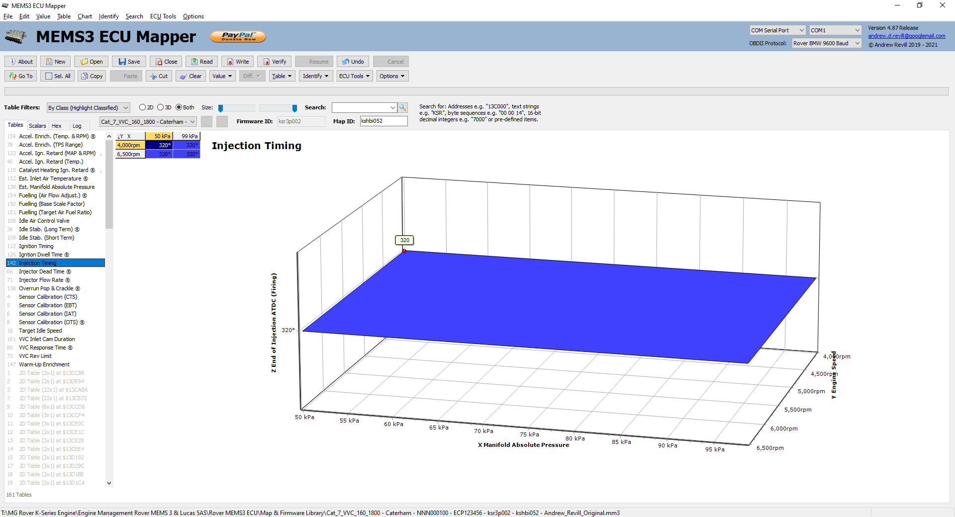
In every MG Rover map that I have seen this has just been a flat value at all MAPs and RPMs, usually 320°.
Injection timing can have a small impact on both performance and emissions. Reading around this subject on the internet, it seems as though there may some small scope for a further performance optimisation by mapping the injection timing but I don’t think it will gain much (especially as some very high performance engines happily run grouped or batched injection, where the timing effectively varies widely between cylinders). At least the facility is there to map it anyway. - Injector
Dead Time ® – This table adjusts the injector pulse
widths to compensate for battery and supply voltage changes.
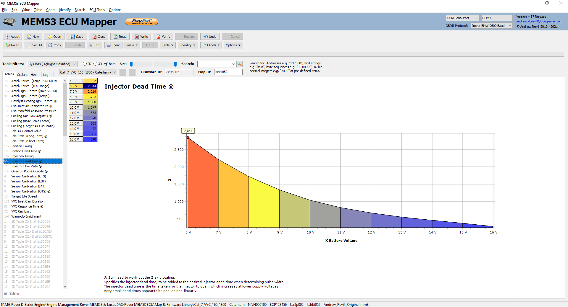
The magnetic force to open the injector depends upon the current flowing, but electrically the injector is basically an inductor (in series with a small resistance) and for an inductor the current changes at a rate dependent on the applied voltage; so the higher the voltage applied to the injector the faster the current builds to the value needed to open the injector.
This results in a significant “dead time” for the injector which needs to be added to time the injector is actually required to be open for when calculating the pulse width, and this dead time correction is strongly dependent on the battery voltage. At lower voltages, larger compensations are required. Without these compensations, the engine would tend to run lean mixtures when the battery voltage was low or electrical loads were high.
From initial testing the numbers in this table don’t seem to be simple additive adjustments; they appear to be non-linear with some element of a percentage of the injector pulse width. This seems illogical as the dead time only occurs as the injector opens (and to a lesser extent, closes), so should not depend on the time it spends open in between.
NB: This table is marked with “®” for “Research” as I still need to track down the precise meaning of the numbers on the Z axis. - Injector
Flow Rate ® - This
table gives the flow rate for the injectors as a function of battery and
supply voltage.
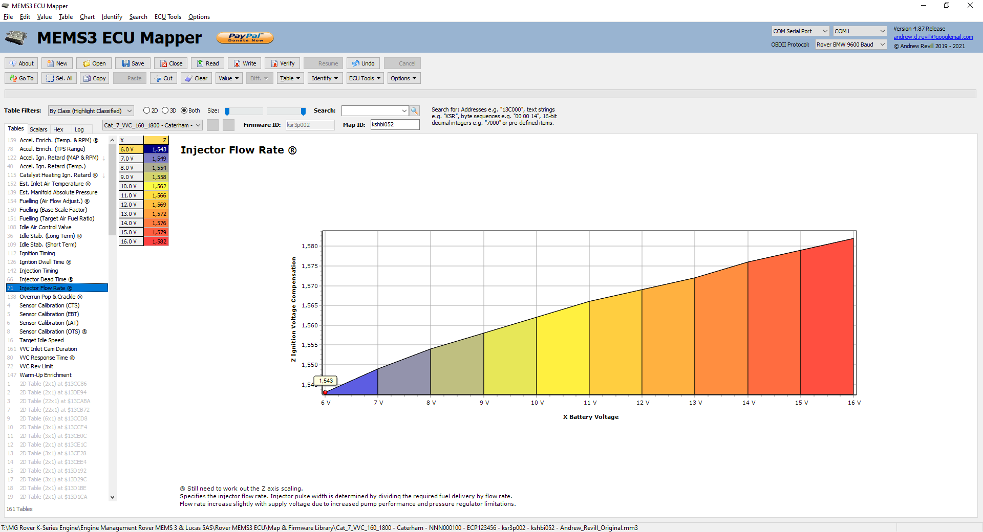
The flow rate for the injectors is slightly affected by supply voltage due to the finite “softness” of the response of the fuel pressure regulator and the increased performance (fuel delivery rate) of the fuel pump at higher supply voltages.
NB: This table is marked with “®” for “Research” as I still need to track down the precise meaning of the numbers on the Z axis. - Sensor
Calibration (CTS) - This table
maps the voltage measured at the coolant temperature sensor onto an actual
temperature value.
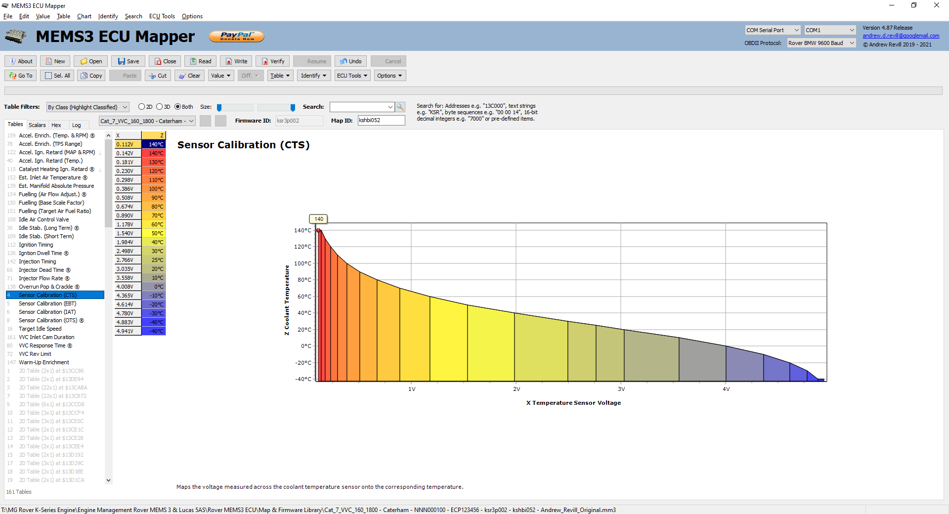
The temperature sensing circuit inside the ECU consists of a stabilised 5V supply in series with a 1.8 kOhm resistor. This forms a potential divider to ground with the temperature sensor. The voltage at the ECU terminal is then measured with a 10-bit analogue to digital converter (on a scale 0..1023). The value returned by the converter is then looked up on the X axis of this table, with the Z axis reading off the actual temperature. I have scaled the axes to read directly in Volts and °C.
Hint: If at some point in the future temperature sensors for these engines become hard to find, this table would allow you to remap to the ECU to match pretty much any standard sensor. - Sensor
Calibration (EBT) - This table
maps the voltage measured at the engine bay temperature sensor onto an
actual temperature value.
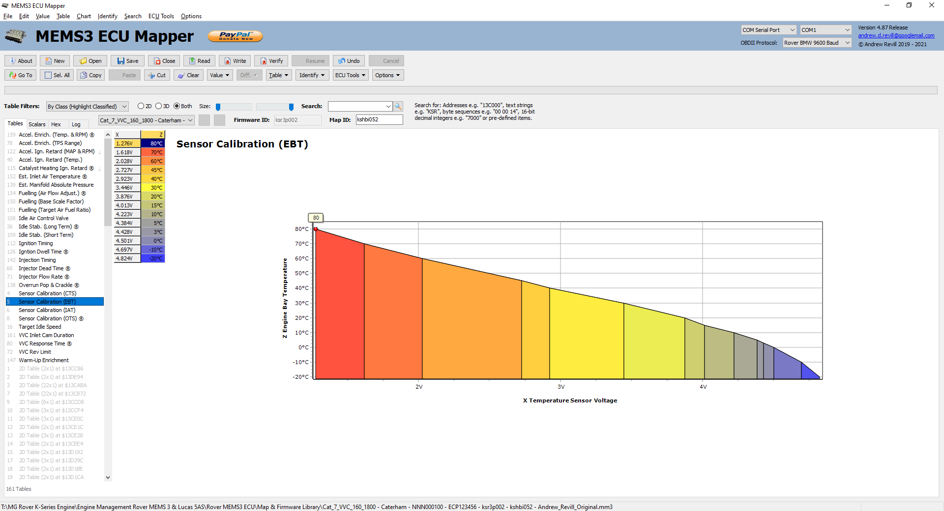
Probably of little use to us Caterham owners, but included for completeness. This table works in the same way as the coolant temperature sensor table described above. - Sensor
Calibration (IAT) - This table
maps the voltage measured at the inlet air temperature sensor onto an
actual temperature value.
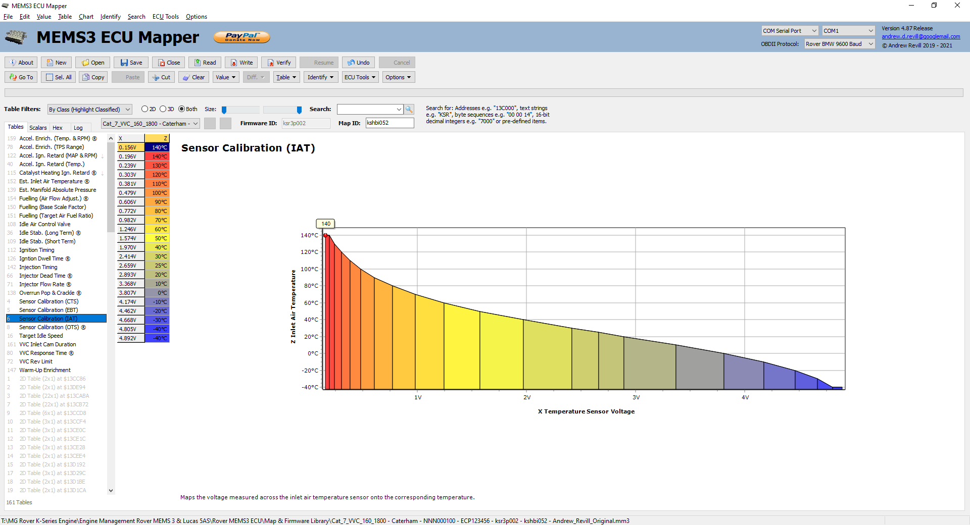
This table works in the same way as the coolant temperature sensor table described above. - Sensor
Calibration (OTS) ® - This
table maps the voltage measured at the oil temperature sensor (where
fitted) onto an actual temperature value.
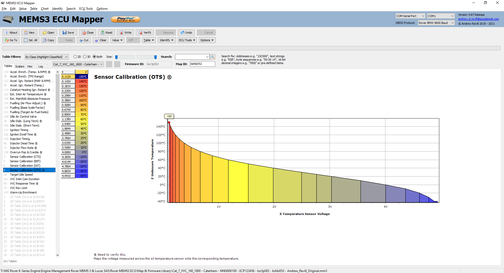
The temperature sensing circuit inside the ECU consists of a stabilised 5V supply in series with a 1.8 kOhm resistor. This forms a potential divider to ground with the temperature sensor. The voltage at the ECU terminal is then measured with a 10-bit analogue to digital converter (on a scale 0..1023). The value returned by the converter is then looked up on the X axis of this table, with the Z axis reading off the actual temperature. I have scaled the axes to read directly in Volts and °C.
Hint: If at some point in the future temperature sensors for these engines become hard to find, this table would allow you to remap to the ECU to match pretty much any standard sensor.
NB: This table is marked with “®” for “Research” as I still need to confirm that this is the correct calibration. - Target
Idle Speed - This sets
the target idle speed according to coolant temperature.
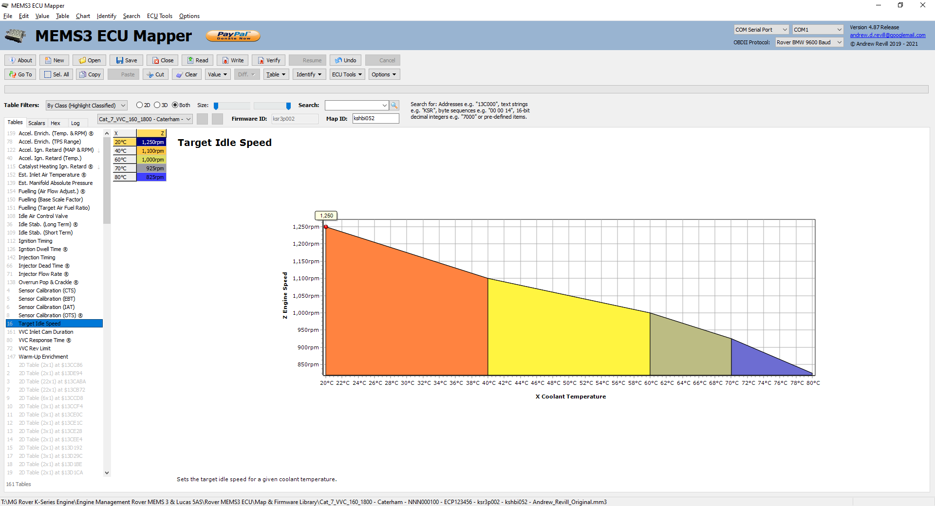
Hint: This could be useful if a modified engine was at all prone to stalling when cold, or where an engine doesn’t idle so well due to cam changes (where an increased target idle speed may well smooth out the idle). - VVC
Inlet Cam Duration - This table
is only present in VVC ECUs. It controls the VVC mechanisms.
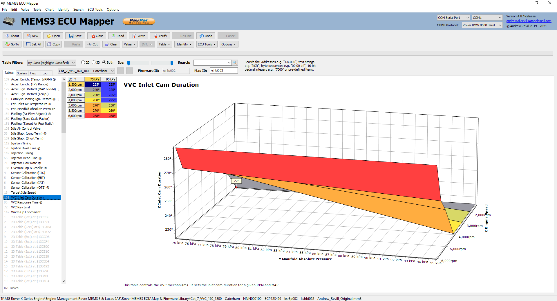
This table sets the nominal inlet cam duration in degrees by MAP and RPM.
Hint: There’s a bit of scope to optimise this table. If you take an average of the 75kPa and 95kPa values and enter these same number against both you’ll be a bit closer to optimal in the mid-range. - VVC
Response Time ® - This table is only present in VVC ECUs.
It tells the ECU how long it will take the VVC mechanisms to respond to a
given step change.
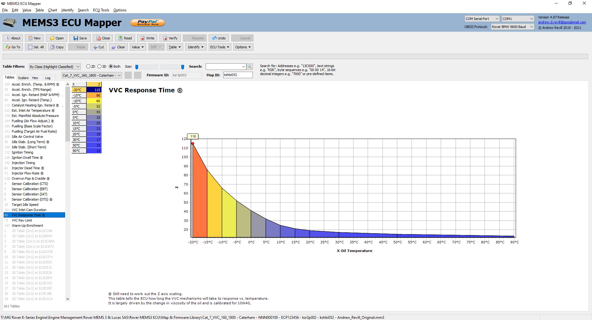
This curve effectively represents the viscosity profile of 10W40 semi synthetic engine oil, which in theory is what the VVC engine should be run on. I did some analysis on the effects of changes to this table, looking at what happened when the numbers did not match the actual response time of the mechanisms. The results were interesting, although I still intend to do the tests again the other way around (i.e. with the standard or correct numbers in the table but a different oil grades) to see how much difference it makes in reality.
In the meantime, this is essentially what I found. Firstly I programmed the VVC mechanism with a standard step-change like this:
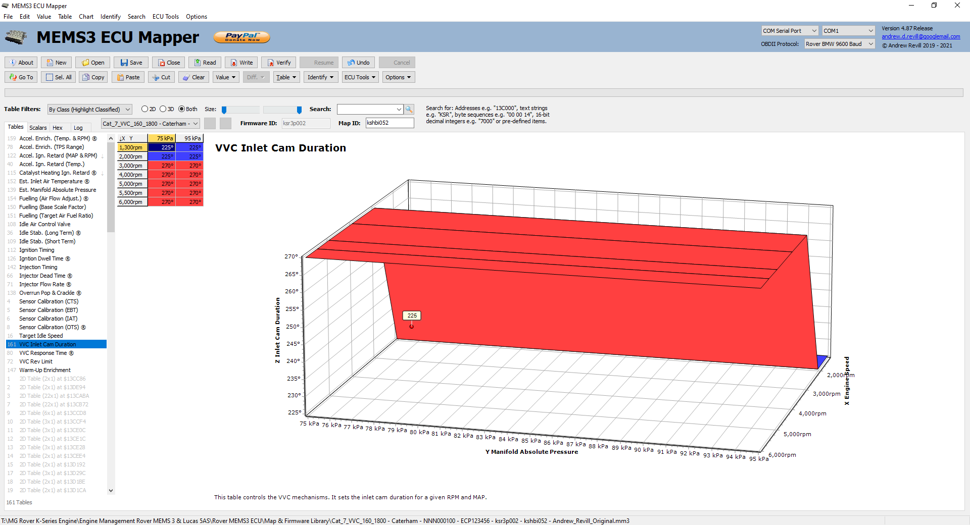
This allowed me to force the VVC mechanisms to move through a well-defined step change by inducing a small increase in RPM. Then I recorded the drive signals to the VVC mechanism increase and decrease solenoids whilst gently blipping the throttle such that the RPM rose through the defined step change and then settled back down again. This is what I saw with the standard values in the response time table. The top trace in green represents the drive to the increase solenoid. The bottom trace in yellow represents the drive to the decrease solenoid:
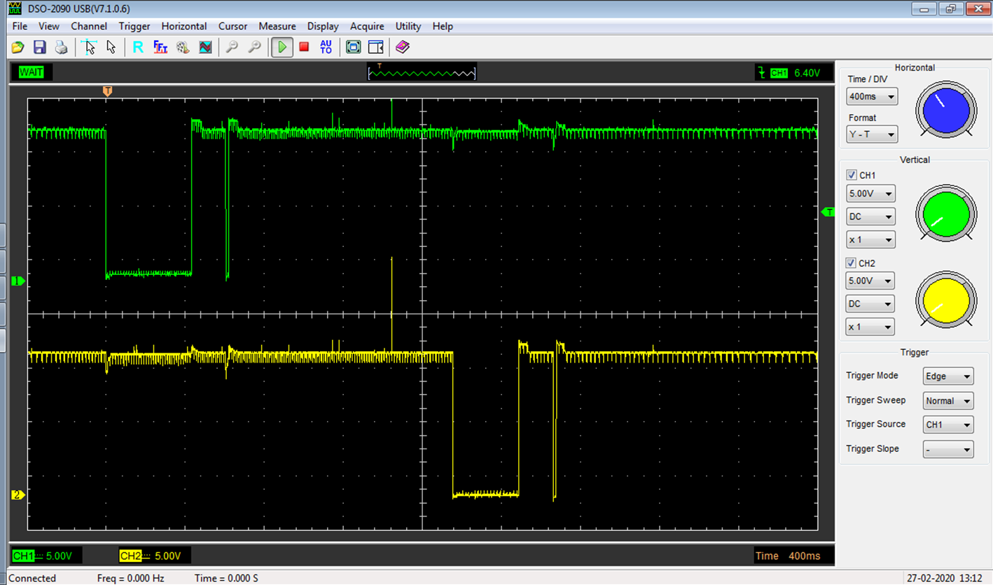
So in each case the ECU seems to be delivering a pulse which is almost moving the VVC mechanisms to the required position, followed by a small corrective pulse. I then increased the numbers in the VVC Response Time table and repeated the experiment. This is what I saw:
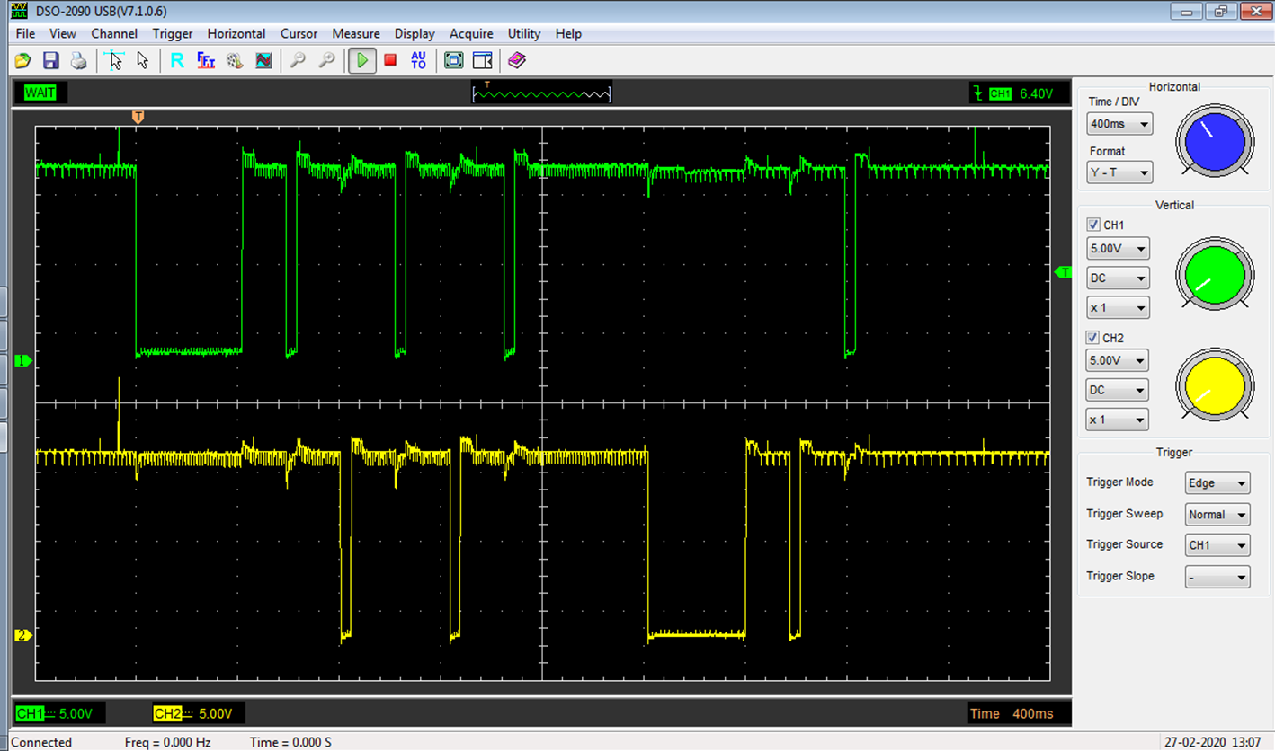
This time the ECU over-compensated, so the initial corrective increase pulse was too long, so it followed up with a corrective decrease pulse, which again overshot etc. The mechanisms were constantly hunting to try to find the correct position. I also tried reducing the values in the table and this is what I saw:

In this case the initial correction increase pulse was insufficient and additional pulses were needed to find the correct position.
NB: This table is marked with “®” for “Research” as I still need to track down the precise meaning of the numbers on the Z axis. - VVC
Rev Limit - This table
is only present in VVC ECUs. It sets the rev limit.
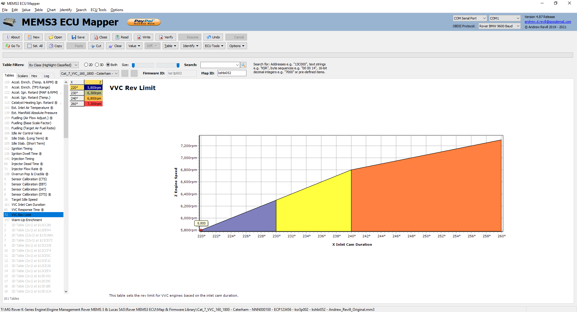
The rev limit is set differently on VVC engines. Where the MPI engines have a single scalar value which is typically set to 7000rpm, VVC engines use a table. The scalar value is still present, but is set to 5800rpm. For VVC engines, the rev limit is defined in terms of the VVC mechanism position, with 5800rpm being the basic rev limit at minimum deployment (and this value then also appears as the scalar rev limit value), increasing to typically 7300rpm at full deployment. This results in the maximum engine speed being limited to an appropriate value if the VVC mechanisms fail. If the ECU loses synchronisation with the VVC cam sensor signal the VVC mechanisms will be frozen at their last known position and the appropriate rev limit will be applied.
Hint: This 7300rpm value can safely be increased to around 7450rpm (if using VVC 160 pistons). Some people push this as high as 7600rpm; personally I would stick with 7450rpm as safe upper limit. - Warm-Up
Enrichment - This table
specifies the percentage additional fuelling at low coolant temperatures.
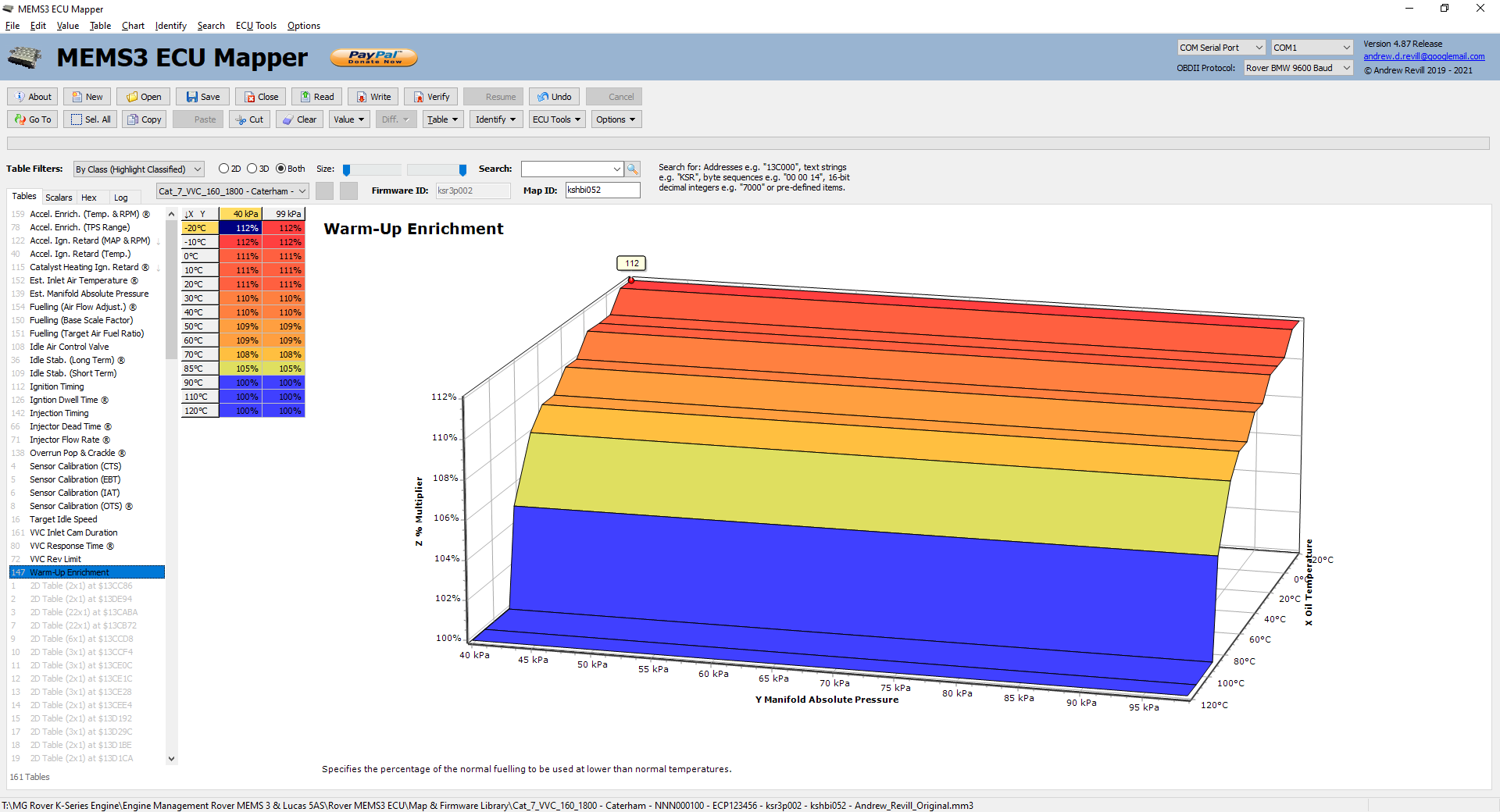
Values typically range from 112% fuelling at -20°C to 100% (normal) fuelling by 90°C.
One interesting consequence of this is that, with the lower thermostat temperature (82°C) and fan temperatures (on at 92°C, off at 87°C) we typically use in out Caterhams, we are barely getting to the point where the ECU considers the engine to have warmed up and uses the mapped normal fuelling numbers during regular driving. Rover used much higher temperature thermostats and the ECU-controlled fan was typically set to come on at 104°C and off at 98°C.
Scalars Identified
I will now go
through the various scalars which I have been able to identify in the maps of
various MPI and VVC ECUs.
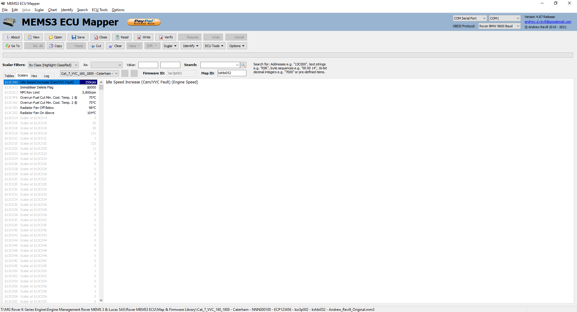
- Idle
Speed Increase (Cam/VVC Fault) -
This sets the increase applied to the mapped rev limit when a fault is
detected with the cam system.
The rev limit is increased by this amount when the ECU detects a fault with the cam position sensor or the VVC mechanisms (e.g. solenoid circuit fault, stuck mechanisms which fail to return to the minimum position correctly). This value is normally set to 250rpm by default in VVC ECUs, which when added to the default idle speed of 825rpm when fully up to temperature raises the idle under fault conditions to 1075rpm. In MPI ECUs the scalar is still defined but is normally set to 0rpm by default. - Immobiliser
Delete Flag - This
controls whether the ECU immobiliser functionality is disabled.
The immobiliser delete flag is one single binary bit in a 16-bit scalar value, in which the other bits are most commonly cleared to 0, but in some ECUs some of the other bits are set to 1. I don’t know what the functions of the other bits are, so they are best left alone. If bit 8 is set to 1, the ECU appears to completely ignore the immobiliser. There is no need to disarm the immobiliser before starting the engine - in fact the immobiliser may be removed entirely. If bit is cleared to 0, normal immobiliser function is restored.
Hint: Again immobiliser delete seems to be a popular request with remaps and it’s something you can easily do at home. Just set bit 8 of this scalar to 1. - MPI
Rev Limit - This sets the rev limit for
non-VVC engines. In a VVC ECU it will typically be set to 5800rpm as
described above. In a non-VVC ECU it will typically be set to 7000rpm. You
can increase or decrease to any value you wish, although increasing it in
an unmodified engine would probably be of no benefit and potentially
rather unwise.
- Radiator
Fan Off Below - This
controls the temperature at which the ECU-controlled radiator fan turns
off. It is typically set to 98°C.
- Radiator
Fan On Above - This
controls the temperature at which the ECU-controlled radiator fan turns
on. It is typically set to 104°C.
Hint: Although in standard setup our Caterhams use a thermoswitch on the radiator to control the fan, it would be very easy modification to enable ECU control. All that would be needed would be a relay with the make contacts connected across the existing thermoswitch connectors, driven by the ECU fan relay pin. The fan on and off temperatures would then be fully programmable through the ECU mapping using these two scalar values.
The Log Tab
On the Log tab you
can a detailed transcript of communications between the application and the
ECU. This includes a millisecond time stamp, a direction (Write / Echo / Read),
the Baud rate used (which should be 9600 for Rover BMW
protocol, 10400 for ISO14230-2 protocol and 360 for the ISO14230-2 Fast
Initialisation pulse). This is followed by a description of the message content
and the actual message bytes.
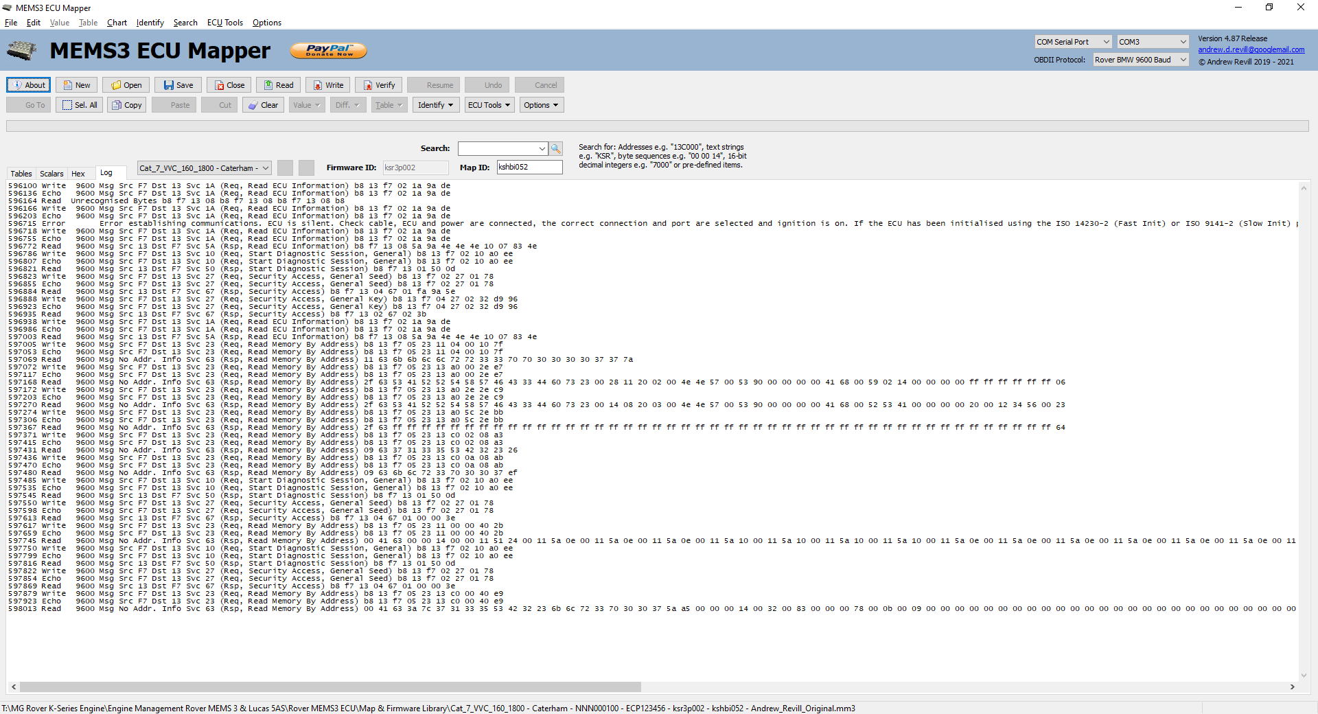
You can Copy or Clear
the log using the buttons or the menus and you can Save the log to a text file.
You should see that
a successful communication with the ECU will consist of a Write, then an Echo,
then a Read.
OBDII
communications with the ECU take place on a single wire (the K Line) which
transmits messages in both directions. Messages usually have “addresses” which
say what device is transmitting and what device the message is intended for.
All devices attached to the K Line see all messages transmitted. This means
that the receive section within the electronics in the OBDII cable sees the
messages sent by its own transmit section as well as messages sent by the ECU.
So any message sent
by the application (Write) should immediately be read back identically (Echo),
followed by any response from the ECU (Read).
The important thing
to realise is that the Echo data comes from the electronics of the OBDII cable
(reading its own transmission as described above) but the Read data comes from
the ECU. Looking at these two therefore gives some important clues for
diagnosing communications issues:
- If you don’t see an Echo, you’re not talking
to a working OBDII cable. This suggests that either the
cable isn’t connected to the PC, the wrong connection or port are
selected, the cable is of the wrong kind or the cable isn’t working
properly.
- If you see an Echo but it doesn’t match the
data sent exactly, this suggests that either some other device is talking
on the K Line at the same time, or there’s a fault in the cable
electronics. Note that you should not try to connect the application and
an OBDII scanner to the ECU at the same time using a splitter cable as
both devices will talk simultaneously and conflict.
- If you see an Echo but no Read, the cable is
working correctly but the ECU is not responding. Possible reasons are that
the ECU is not powered up or the ignition is switched off, the ECU is in
some state where it is not expecting communications (often after an
interrupted communication, but sometimes it just seems they can be a bit
temperamental on the communications side - try switching the ignition off
for a period of time or disconnecting the ECU briefly). The other
possibility is that you are talking to the ECU using the Rover BMW
protocol after it has been initialised using ISO14230-2 protocol - in this
case the ECU will completely ignore communications. See my notes on OBDII Protocols above for more information.
Difference Mode
This allows you to
compare two maps and only display the tables or scalars with differences. You
can only compare two maps for the same firmware version as the table and scalar
structures will not correspond between maps for different firmware versions.
Once you have
opened two or more files, go to the file which you want to compare and click Difference. Difference is found on the
main menu and as a button on the button bar. You will see a drop down menu which
allows you to choose which other file you with to compare it with.
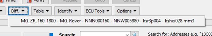
Choose the file you
wish to compare to and you will then see that both tables and scalars are
filtered down to show only those with differences (in this case the only
differences were the pop and crackle settings in the Ignition Timing and Overrun
Pop & Crackle tables and the increase in some scalars). You can then
use Ctrl-Tab to switch between the
files and eyeball the differences which will stand out as you switch between
them.
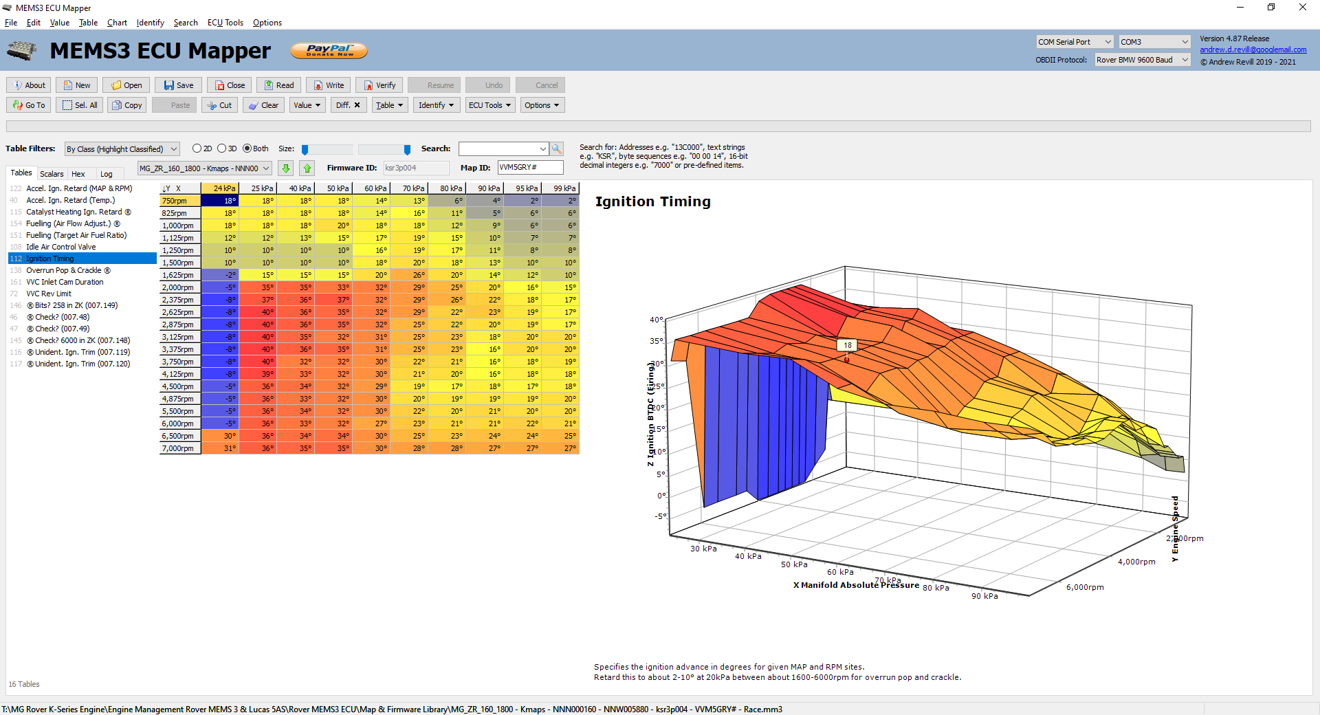
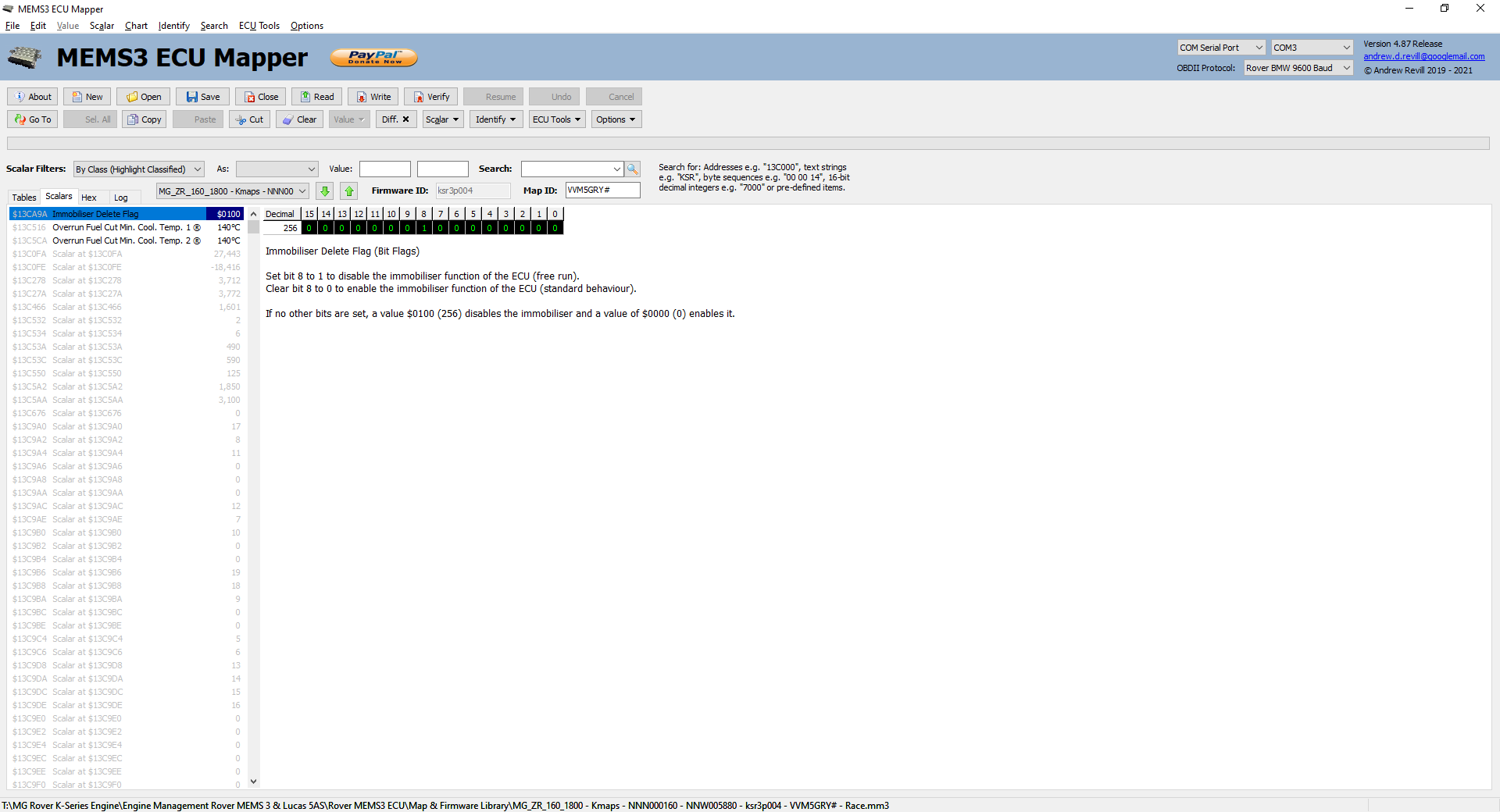
To exit Difference mode, simply click the Difference button again.
ECU Tools
The ECU Tools menu gives access to a few
useful actions you may wish to perform on the ECU.
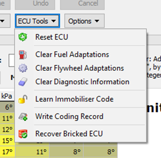
- About
ECU - This gives information about the
ECU, firmware and map in the following format:
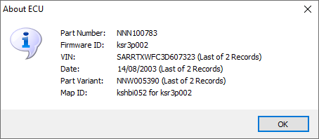
- Reset
ECU - This allows you to reboot the ECU.
If the ECU is in a running condition you will hear the fuel pump prime
again. This operation is slightly unusual in that I have coded it to use
the IS14230-2 protocol even when the Rover BMW protocol is selected at the
top of the screen. This is useful for the following reasons:
- When the ECU initially boots up, it talks
the Rover BMW protocol. Once the ECU has been initialised into the
ISO9141-2 or ISO14320-2 protocol, it will only talk ISO protocols until
it is rebooted. This is because there is no initialisation signal for the
Rover BMW protocol, so no way to signal to the ECU that you want to go
back to it. The only way to get back to Rover BMW protocol is to reset
the ECU.
- If the ECU is currently using the Rover BMW
protocol, issuing the reset command using the Rover BMW protocol will
obviously work fine. Issuing the reset command using the ISO14320-2
protocol will work also fine as it will just initialise the ECU into ISO
mode as it goes. So this allows the reset command to be used whatever
protocol the ECU is currently expecting.
- Once the reset command has been issued and
acknowledged, this option performs no further communication with the ECU.
This means that it always leaves the ECU freshly booted, in a condition
where it will accept communications in either protocol.
- Therefore resetting the ECU using this
option should always be able to bring the ECU back to a state ready for
communications in the selected protocol, irrespective of what the
selected protocol is and what protocol the ECU is currently talking.
- Clear
Fuel Adaptations - This will
clear any fuelling adaptations in the ECU, as they may not be appropriate
with a modified map. The ECU will readapt over a couple of hundred miles
of mixed driving. During this time the emissions and fuel economy may not
be as good as they normally are as the fuelling may be slightly incorrect.
- Clear
Flywheel Adaptations - This will
clear any flywheel adaptations in the ECU. The ECU learns the precise
characteristics of the flywheel trigger pattern in order to help it detect
misfires accurately. The ECU will readapt over a couple of hundred miles
of mixed driving. During this time misfire detection may be disabled.
- Clear
Diagnostic Information - This
clears any diagnostic information and DTC fault codes in the ECU. The ECU
will then continue to log new diagnostic information for any current
faults.
- Learn
Immobiliser Code - This clears
the immobiliser coding and tells the ECU to re-learn it from the
immobiliser. The ECU will then be free-running initially but the first
time it sees the immobiliser disarmed it will learn the code and again be
paired with that immobiliser.
- Write
Coding Record - This allows
you to write a new coding record to the ECU with a new date, VIN and Part
Variant number. See below for more
information.
- Recover
Bricked ECU – This option
allows you to easily recover an ECU which has been bricked by writing
incompatible, incomplete or corrupted firmware or map data to it.
Write Coding Record
This option allows
you to write a new lower coding record to the ECU. The coding records look like
they were written to the ECU whenever it was reprogrammed by Rover. Most ECUs
only have a single lower coding record, although some have two which suggest
that these ECUs were reprogrammed with updated maps or firmware at some point.
The lower coding records contain (amongst other unidentified information) the
date on which the record was programmed and the VIN and Part Variant codes (a
part number usually starting with NNW, which identifies the combination of
hardware and software builds, whereas the Part Number starting with NNN
identifies the hardware build only). As far as I can tell, the coding area
cannot be erased (i.e. the ECU doesn’t provide a routine to erase it, the only
way to erase to it would be to crack the ECU open and desolder the memory chip
and reprogram it on a PC). I think the idea is that the coding records form a
permanent, indelible record of the ECUs history. You can only add new records
after the existing records, you cannot erase or update (without corrupting, as
you can only reprogram binary 1s to 0s and not the other way around without
erasing) existing records.
The MEMS3 Mapper
application allows you to add lower coding records to the ECU with your own VIN
and your own Part Variant codes if you wish. I have coded modified ECUs to my
car’s VIN number and used the Part Variant ADR999999. The first 3 characters
can be alphabetical or numeric, the last 6 characters
must be numeric digits (they are stored as 2 digits per byte in BCD coding).
Remember that once
written, you cannot edit or erase the coding record.
To write a new
coding record, click Write Coding Record.
Write Coding Record is found on the
main menu and the drop down menu on the ECU
Tools button. The application will download the existing coding records
from the ECU and display a dialog as shown below:
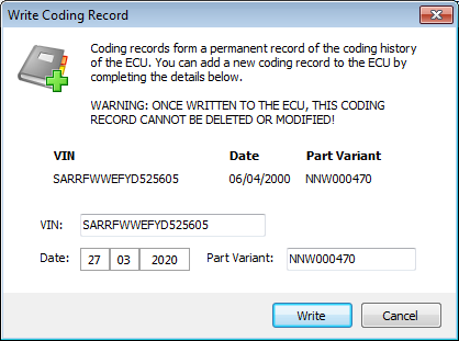
Enter your VIN
(which will default to the VIN taken from the last current coding record), the
date (which will default to today’s date) and Part Variant code (which will
default to the Part Variant code taken from the last current coding record. The
first 11 characters of the VIN can be alphabetical or numeric,
the last 6 characters must be numeric digits (they are stored as 2 digits per
byte in BCD coding). The first 3 characters of the Part Variant can be
alphabetical or numeric, the last 6 characters must be
numeric digits (they are stored as 2 digits per byte in BCD coding).
The coding records
don’t seem to affect the operation of the ECU in any way, they are effectively
documentation. In order to try to ensure that the ECU will still read back
correctly on Rover equipment, the new coding record is copied from the last
current coding record and the three fields above are then updated. This means
that any other fields which are not understood are left unchanged.
Click Write to write the new coding record to
the ECU.
Recover Bricked ECU
This option allows
you to easily recover an ECU which has been bricked by writing incompatible,
incomplete or corrupted firmware or map data to it.
In addition to the firmware and map, the EEPROM chip contains a
boot loader program. When a brand new virgin ECU is suppled, the boot loader is
all that is present. The boot loader has sufficient functionality to allow the
ECU to communicate with a programmer and load the firmware and map. The boot
loader generally checks to see whether valid firmware and map are present and
if so, shortly after the ECU boots it transfers control straight to the firmware.
The boot loader initialises watchdog timers which reboot the ECU if the
firmware appears to have hung up, and what generally seems to happen in the
case of a bricked ECU is that the boot loader sets up the watchdogs, transfers
control to the firmware which fails to operate normally, the watchdogs detect
this and reboots the ECU which then just repeats the same cycle. The ECU is
stuck in an indefinite boot loop. You usually see the fuel pump starting to
prime then being switched off again several times a second forever. Because the
ECU is constantly rebooting, you never get the chance to establish stable
communications with it so cannot even begin to reprogram it with valid firmware
and map.
The boot loader code is protected and permanent. It is loaded into
the first sector of the EEPROM chip at manufacture and the ECU does not appear
to provide any method to erase or modify it. Certainly my MEMS3 Mapper and
Flasher tools never touch the boot loader in an ECU. This means that whatever
we do to the firmware and map, however badly we screw those up to brick the
ECU, the boot loader will still be clean and valid and just the way it was the
day the ECU was manufactured.
The ECU checks for a specific request on the OBDII K-line as it
boots up. If it detects this request, it does not attempt to execute the
firmware but remains in the boot loader ready to accept programming and sends a
response. When you select this option, the application will begin to broadcast
the request code at regular intervals and monitor for the expected response. If
the ECU is stuck in a boot loop, constantly rebooting, it should recover almost
immediately as the next time it reboots it will detect the request and remain
in the boot loader ready to accept programming. If the response is not detected
within a short time, the following dialog is displayed:
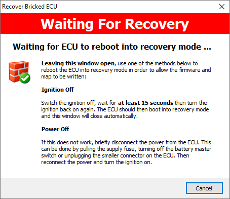
If the ECU is hanging and unable to communicate, we need to
persuade it to reboot. Switching the ignition off for at last 15 seconds (and
then back on again) is usually sufficient to ensure that it will perform a full
boot when powering on again. At this point it should again remain in the boot
loader ready to accept programming as above. If the ECU was really tightly stuck
in a loop, then just occasionally switching the ignition off is not sufficient
to break it out of the loop and trigger a reboot. In this case, you need to
briefly remove power from the ECU. When power is re-applied and the ignition is
turned on it will boot again, detect the request and remain in the boot loader
ready to accept programming as above.
Depending on the timing of the request code, it may occasionally
require more than one attempt to recover an ECU.
When the expected response is detected, the following dialog is
displayed:

Once the ECU has recovered into a state where it is running the
boot loader and willing to communicate with the application again it is
important that you then write a good replacement firmware, map or both
(depending on what was damaged, if in doubt do both). The initial recovery is
only temporary; we have broken the ECU out of the cycle that was preventing it
from communicating and accepting programming using the special code, but next
time it reboots without seeing the request broadcast it will of course continue
to try to execute the damaged firmware or map as before. In recovery mode, some
of the ECU tools and operations will fail (the ECU will reject the operations
as it will not be running the firmware) and it will not provide any engine
management functionality, but everything necessary to read and write the
firmware and map will function normally.
Once you have rewritten the ECU the repair will be permanent.
Options
The Options menu allows you to change a few
configuration options for the application. In addition it provides links to
contact me. Some other configuration options are saved by the application
automatically between sessions. These include:
- The selected
view (By Index (Highlight
Classified), By Class
(Highlight Classified) or Clean
(Classified Only)).
- The selected communications device and
protocol.
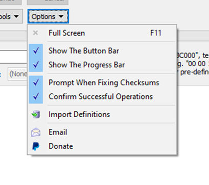
Options which you
can configure through the Options
menu include:
- Full
Screen - This toggles the application
window between normal and full screen mode, where it hides the Windows
task bar.
- Show
The Button Bar - Allows you
to show and hide the button bar at the top of the window.
- Show
The Progress Bar - Allows you
to show and hide the progress bar at the top of the window.
- Prompt
When Fixing Checksums - When this
options is checked, the application will prompt you when a checksum needs
fixing and ask you to confirm whether you want the application to fix it.
Checksums are verified when saving a file to disk or when writing to the
ECU. Fixing the checksums when saving a file is optional; you can save a
file with the wrong checksum if you want. When writing to the ECU, the
application will not let you continue with an incorrect checksum as this
can lead to a bricked ECU. When this option is unchecked, the application
will proceed to correct checksums automatically without prompting.
- Confirm
Successful Operations - When this
option is checked, the application will display a confirmation message
after an operation completes successfully, e.g. “ECU Read OK”. When this
option is not checked, no confirmation is displayed on success (but error
messages are still displayed on failure).
- Import
Definitions - This allows
you to import a definitions file. It is intended to allow you to download
an updated version of the application and its updated definition file
without losing any changes you may have made to definitions in the earlier
version. When you click Import
Definition you will be prompted to select a definitions file (normally
called MEMS3Mapper.def) to
import. You will then be asked to confirm whether you want to update
existing definitions:
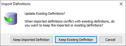
When a setting in the imported file conflict with a setting in the current definitions:
Keep Imported Definition will keep the setting from the imported settings file, overwriting the setting in the current definitions.
Keep Existing Definition will discard the setting from the imported settings file, retaining the setting in the current definitions.
All of these
settings are stored in a file called MEMS3Mapper.set
in the same folder as the application executable file when the application
is closed. You can revert everything back to standard
settings by deleting this file. You will also see files named MEMS3Mapper.def and MEMS3Mapper.dat which contain the
table, scalar and axis definitions and the data used for matching classes in
new firmware versions respectively.
ECU Compatibility
There is no check on whether the firmware
you are flashing is compatible with the actual ECU you’re flashing it to. The
firmwares don’t seem to contain hardware part numbers to cross-check. I guess
that’s something that was managed by Rover’s Testbook and production systems
originally.
Whilst
experimenting with all of this I’ve flashed a lot of maps onto quite a number
of different ECUs. This includes a lot of invalid combinations such as flashing
a VVC firmware and map onto a non-VVC ECU which doesn’t have all the
electronics necessary to drive the VVC system. In all cases the ECUs still ran
the engine, and surprisingly well too. It certainly doesn’t seem to cause any
major problems flashing a firmware for a different kind of MEMS3 ECU - I’m not
saying it will run the engine properly as for example all of the VVC control
would be missing in the above case, but what I am saying is that it looks unlikely
that you will break anything trying, and you can always reflash the ECU more
appropriate afterwards.
As far as I can
determine (and this may or may not be absolutely correct), at least as far as
the systems we run in our Caterhams are concerned, due to the modular nature of
the ECU design there effectively only three different categories of ECUs:
- MPI (non-VVC),
Manual ECUs.
- MPI (non-VVC),
Automatic ECUs.
- VVC ECUs.
The automatic ECUs
include additional electronics including a CANbus controller to talk to the
gearbox. However, when flashed with firmware and map from a manual ECU they
just seem to happily ignore the extra peripheral electronics and run quite
happily. As we don’t run automatic gearboxes this means that the first two of
the above appear to be interchangeable for our purposes.
The VVC ECUs
include additional electronics associated with processing of the VVC cam
signals and drive of the VVC mechanism solenoids. However, when flashed with
firmware and map from a non-VVC ECU they again seem to happily ignore the extra
peripheral electronics and run quite happily as manual ECUs.
Non-VVC MEMS3 ECUs
of various different types are readily available at very cheap prices on eBay
(from about £7.00 - I’ve bought quite a few for experimentation whilst working
on this project). As far as I can see from the experiments I’ve done, any one
of these can be flashed with a full firmware and map copied from any non-VVC
ECU we use, whether it has a standard Rover map, Caterham Supersport
modifications or a custom modified mapping to give a fully functional cloned
ECU. This means that the pool of spares available is quite large and it becomes
economical to flash a spare copy just in case it is needed in the future,
especially if you have something modified, rare and potentially expensive to
replace.
VVC ECUs tend to be
more expensive. You can though still pick up used ones for around £50 and there
are some brand new ones up for sale at the moment for £99.95. The most common
VVC ECU part numbers are NNN000100 (MGF Trophy) and NNN000160 (MG TF and ZR). I
have flashed firmware and maps between these two without any problems at all
and have run both in my car.
Future Plans
I’ve got the
application to a usable condition. So far I’ve focused mainly on the technical
aspects of communicating with the ECU, safely reprogramming it, decoding the
memory map, decoding and interpreting the map and presenting it to the use for
display and modification. I’m aware that it may still be lacking an extra layer
of tools on top which would make it more usable in a live mapping situation. I
have to confess at this point (maybe a bit late in the write-up!) that I have
very little direct experience of actually remapping engines, so I would welcome
comments and suggestions on features which might make it more usable. I’m
thinking of facilities for bulk increasing or decreasing regions of tables,
interpolation, smoothing etc. All of these things could easily be layered on
top of the foundation I have built so far.
One feature that I
think will be very hard to add is a “live adjustments” capability of the kind
the Emerald software has. This would allow you to adjust map values while
engine was running, but I just don’t think the ECU supports this feature - or
if it does I don’t think I’d be likely to be able to find a way to discover it
unless I had access to another tool which provided this feature and was able to
“sniff” the communications to see how it was done. As far as I can see from the
data sheet the 29F200 EEPROM chip only supports block erase of whole sectors at
a time, and you can’t reprogram a 0 to 1 without erasing, so the only way to
sensibly write any changes to the EEPROM is to bulk erase and rewrite, which
would require the engine management functions to be shut down (they couldn’t
continue to execute whilst erased).
I’d also like to
continue to track down more ECU features. In order to be able to find
something, I really need to know:
- That a
particular feature exists, and a reasonable definition of it.
- How to measure it, actually on my car or on
a test rig.
Given those I think
I would stand a reasonable chance of tracking down the control of a particular
feature in the ECU. I don’t think I’ll have much more success just staring at
tables and thinking about what they could be as I think I’ve got all of the
obvious ones. There are still many more tables in the ECU for which I haven’t
yet been able to identify a function.
If anyone has
access to a Testbook T4 or other system that allows other features to be
updated I’d love to spend some time logging the communications so I can decode
how it’s done but I don’t really expect many of the “usual suspects” to take me
up on that!
If anyone is able
to spot any additional feature control in an ECU, I’d love to receive feedback
so I can incorporate them into the definition files I’m supplying with the
application.
I’m aware that this
write-up is already a very long post. Even then I’ve not gone into full detail
and I haven’t documented all features. Hopefully the rest of it is intuitive
enough for you to find your way around once you start using it.
Change Log
|
4.56 |
Further development of MEMS3Browser. |
|
4.57 |
Further development of MEMS3Browser. |
|
4.58 |
Further development of MEMS3Browser. |
|
4.59 |
First full release of MEMS3Browser. |
|
4.60 |
Fixed: Sometimes refresh led to blank source display in Browser. |
|
4.61 |
Double-click handlers for tree views in Browser inconsistent;
removed. Use popup menus instead. |
|
Double list view replaced with single list view in Browser. |
|
|
4.62 |
Double tree view replaced with single tree view with
"Uses" and "Used By" nodes in Browser. |
|
Fixed: Numerous teething issues in Browser. Fairly extensive
restructuring for usability. |
|
|
Separate identification of "Local_Var" and
"Boot_Var" in Browser. |
|
|
Double-click handlers for tree views in Browser reinstated as
can be made consistent in new view. |
|
|
Added options to export lists of element Source Name and Display
Name to Browser. |
|
|
4.63 |
Extensive further development of MEMS3Browser. |
|
Added history list, tracking of
"Modifies"/"Modified By" as well as "References"/"Referenced
By". |
|
|
Added highlighting of referenced elements. Added caption bars. |
|
|
4.64 |
Fixed: File combo not updated with new file name after saving
file. |
|
Fixed: SIGNIFICANT BUG: If READ is interrupted and user clicks
Resume, data read is incomplete. Write not affected. |
|
|
4.65 |
Extensive further development of MEMS3Browser. |
|
Now support comments as hints for all elements. |
|
|
Subroutine comments attached to labels. |
|
|
4.66 |
Extensive further development of MEMS3Browser. |
|
4.67 |
MEMS3Mapper now allows .DEF settings files to be imported.
Useful when upgrading when definitions have changed. |
|
4.68 |
Settings files no longer store keys for blank string values. Old
files cleaned up. Needed to distinguish explicit blank from null for hint
formatting. |
|
MEMS3Mapper definitions and comments now appear in hints for
tables and scalars in MEMS3Browser. |
|
|
4.69 |
MEMS3Browser now uses the MEMS3Mapper definitions file exclusively
for tables and scalars when firmware ID specified. |
|
MEMS3Browser now has table of all 68000 opcodes and operands and
uses these to determine references/modifies correctly. |
|
|
4.70 |
Extensive further development of MEMS3Browser. |
|
4.71 |
Extensive further development of MEMS3Browser. |
|
4.72 |
Extensive further development of MEMS3Browser. |
|
4.73 |
Extensive further development of MEMS3Browser. |
|
4.74 |
Now respects locale settings for display and editing. Uses fixed
EN-GB settings for all settings files. |
|
4.75 |
Message rate throttled with 10ms inter-message delay. This
avoids timeouts during long writes using ISO14230-2. |
|
4.76 |
Message rate throttling algorithm optimised. |
|
Status bar panel widths and message text adjusted for
consistency. |
|
|
4.77 |
Dependency on GetTickCount64 removed. Now compatible with
Windows XP again. |
|
4.78 |
Option to correct checksums removed. Checksums now ALWAYS
corrected on write to ECU or save to file. |
|
Checksums now verified on read from ECU or load from file.
Incorrect checksum marks firmware, coding or map as invalid, preventing write
to ECU. |
|
|
Search items added for Firmware Valid Flag, Coding Valid Flag
and Map Valid Flag. |
|
|
Fixed: Edit menu shortcuts prevent normal shortcuts for Cut,
Copy, Paste, Clear, Select All and Undo working
within edit controls. |
|
|
Application now brought to foreground on opening a file (e.g. by
double-clicking in Explorer) where operating system permits. |
|
|
Fixed: Sounds played by confirmation and other dialogs blocking
serial ports on VMWare virtual machines. |
|
|
4.79 |
Math menu and functions added, incorporating feedback from
Northampton Motorsport. |
|
When saving 256kB files now prompts for boot loader file rather
than hard coding boot loader. Sample boot loader files included in
distribution. |
|
|
4.80 |
Optimisation of table chart redraw and
keystroke buffering for rapid repetitive key presses. |
|
|
File extensions and file sizes now used to identify formats.
192kB files always in Flasher order. BIN files of other sizes in EEPROM
Reader order. |
|
4.81 |
Further rationalisation of file formats supported in order to
allow correct identification by file extension and size. |
|
4.82 |
Further rationalisation of file formats supported – legacy file
format support restored and Galletto file format added. |
|
|
Fixed: Opening a map file into an existing file was causing the
firmware to be marked as invalid. |
|
|
Math menu item and button renamed as Value. |
|
4.83 |
Fixed: Millisecond timestamps on logs incorrect (additional
multiplication factor of 1000 included in calculation). |
|
|
Fixed: Save button enabling part way through read if clipboard
content change forced a menu refresh. |
|
4.84 |
Fixed: OK button on About dialog misaligned. |
|
4.85 |
Escape key now aborts edit in signed and unsigned edit boxes. |
|
|
Warning displayed on attempt to edit memory contents directly.
Yes/No confirmation, default No. No further prompts in session if user
selects Yes. |
|
4.86 |
Fixed: Value menu items should only be enabled on the Tables
tab. |
|
|
Fixed: Popup menu items flicker badly for several seconds if the
clipboard contents change while they are dropped down. |
|
4.87 |
Fixed: Conflicting Ctrl+F shortcuts. Shortcuts adjusted to
resolve. |
|
|
Memory edit warning now also displayed for Cut, Paste and Clear
on the Hex tab. |
|
|
Recover Bricked ECU functionality added. |
|
4.88 |
Fixed: Some controls were not disabled when an action thread was
running. |
|
|
About renamed as About ECU. About File menu item added. |
|
4.89 |
Bricked ECU recovery system tidied up. Boot loop does not
display dialog. Dialog closes on recovery. Recovery mode banner on About ECU. |
|
4.90 |
Slow boot loops seen in testing. Recovery time allowed extended
to 600ms, polling at 10ms intervals to detect early recovery. |
|
|
Discovery TD5 diesel boot loaders added. |
|
|
Family combo box added. Allows selection of Petrol (with 5AS/Pektron
Immobiliser), Petrol (with BMW EWS 3.D) or Diesel. Restricts features. |
|
Recovery dialog visually updated with red banner. |
|
|
4.91 |
Family support tidied up. Lucas and Pektron families separated
for future support. Family names adjusted, combo box wider, title font
smaller. |
|
|
Full MEMS3 tools suite now released as both 32-Bit Windows and
64-Bit Windows executables. |
|
4.92 |
User interface now fully supports High-DPI scaling on high resolution
displays. Column widths calculated dynamically. |
|
4.93 |
Fixed: MEMS3 Mapper will not load correctly on early Windows XP.
Dependency on Add/RemoveClipboardFormatListener APIs worked around. |
|
4.94 |
Clear diagnostic information now disabled for TD5 diesel ECUs.
Will be re-enabled if and when correct commands identified. |
|
|
FTDI and Qinheng cable drivers included in distribution. |
|
4.95 |
Fixed: Ctrl-Z shortcut not triggering Undo when an edit box has focus,
even though Ctrl-Z does nothing in an edit box. |
|
|
Fixed: Scalar maximum value edit sometimes incorrectly updated
to match a smaller value in the scalar minimum edit. |
|
4.96 |
10 most recent files accessed in MEMS3 Mapper now accessible from
the File | Recent menu. |
|
4.97 |
Fixed: Menu font DPI scaling incorrect. Recent file menu items
drawn a lot wider that necessary. |
|
Fixed: MEMS3Browser not correctly renaming table and scalar
classes in MEMS3Mapper definition file. |
|
|
|
References to overrun fuel cut temperature scalars removed from
release as I no longer believe those definitions to be correct. |
|
|
Fast hashed settings objects introduced. Much faster UI handling
of settings and definitions. Definition dialogs much more responsive. |
|
4.98 |
Fast escape/unescape routines introduced. Further improvements
to UI handling of settings and definitions. |
|
|
Fixed: Double-escaping of characters (e.g. “ “
-> “%20” -> “%2520” in recent file names). |
|
|
Fast single-table refresh now used for
increase/decrease/multiply/divide and corresponding undo operations. Now
tracks fast key presses. |
|
4.99 |
Current working disassembly included in distribution in Sample Files
folder, for use with MEMS3Brower. |
|
|
Fixed: Section name not escaped in TSettings.EraseSection; old
class names not removed when classes renamed, unable to revert to old name. |
|
|
Fixed: MEMS3 Browser circular reference deduplication logic
incorrect. |
|
|
Fixed: Labels on the Hex tab not wide enough, truncating text on
high-DPI scaled displays. |
|
|
MEMS3 Terminal now supports Debug protocol; equivalent to Rover
BMW protocol but running at 256,000 Baud instead of 9,600 Baud. |
|
|
Fixed: Ctrl-V not pasting into Hex grid when combo box with
csDropDown style is focused. |
|
|
Support for S-Record firmware patch files added, with firmware
version compatibility check. Base Debug file added to distribution. |
|
|
Communications log now always updated live. No delay on
switching to log tab. Slightly slows down reading and writing but this aids
stability. |
|
|
Default now is not to verify ECU after writing. Writes are
protected by checksums anyway. Option still remains. |
|
|
On error reading or writing, the connection is now released
before the error message dialog is displayed. |
|
5.00 |
Currently selected COM port or FTDI not removed from list even
when no longer available. Prevents the device being “forgotten” on sleep etc. |
|
|
On failure to open a port, a message is now broadcast globally
before retrying. MEMS3 Terminal will then stop if it has the port open. |
|
|
Maximum debug patch Baud rate reduced from 256000 Baud to 127400
Baud for reliability reasons. 72800 Baud and 9600 Baud options added. |
|
|
Current working document is now referred to as a “Project”
rather than a “File” for clarity. |
|
|
Checks for firmware and map presence now use 5AA5 signatures as
used by the ECU itself when checking whether to launch the firmware. |
|
|
Firmware checksum correction address moved from $139FF0 to
$139FFC to maximise firmware space available for alternate map. |
|
|
ECU Tools renamed as Tools. Sub menus for ECU Tools and Project
Tools. Project Tools menu to include map switching options. |
|
|
Map switching on Pin 63 custom functionality added. |
|
|
Ability to import map only from another file added. |
|
5.01 |
Failed silently when attempting to read ECU if OBDII cable
completely dead. No error hander for faInitialiseFirmware or faInitialiseMap. |
|
|
Engine Bay Temperature sensor calibration curve identified as
Table 7 not Table 5. Table 5 is unused temperature sensor on Pin 47. |
|
|
Map switching on Pin 47 custom functionality added. Map
switching functionality documented. |
|
|
Column widths adjusted on TIdentifyForm to allow for font
scaling. |
|
|
Table and scalar identifications updated for all known
firmwares. |
|
5.02 |
Map switching on Throttle custom functionality added. |
|
5.03 |
Fixed: Logic for enabling and disable Difference and No
Difference menu items and buttons wrong. Cannot clear difference selection. |
|
|
Disassembler Binary 256KB|*.68k file format introduced. Full
256KB EEPROM dump but NOT byte-swapped like EEPROM Reader files. |
|
5.04 |
Custom tool framework added. EASy68K to L68 to INC, directly incorporated into project. Much easier to
maintain assembly patches. |
|
|
All map switching methods now dynamically position the alternate
map based on firmware size to make best use of space. |
|
|
Memory Dump custom tool added (development mode only). |
|
|
First prototype for Live Map custom tool added (development mode
only). |
|
5.05 |
Various tidy-ups and small fixes to the dynamically linked
custom patches. |
|
5.06 |
Improvements to Memory Dump Utility. Communications timeouts added.
Alignments of flag bits corrected. |
|
5.07 |
Fixed: Table Filter combo box text is editable. |
|
|
Menu item aggregation logic changed. Recent1 remains visible but
not Enabled when no recent files. |
|
|
Options, Extended Retries added to Flasher and Mapper. Allows
successful read (not write) with noisy connections. Slower to stop on genuine
error. |
|
|
Option to Clone Project Coding Record added. Clones all fields
from the project coding record, including those not decoded by the
application. |
|
|
Separate .DEF files for Petrol and Diesel. Diesel map
definitions and sample data now included in main distribution. |
|
|
Automatic “guess” at Family based on Firmware ID. Family now per
file. User can override automatic family guess. |
|
|
Legacy file formats (all .MM3 format files with .BIN extensions)
removed from the list of formats in which files can be saved for clarity. |
|
|
Automatic initial file name generated on reading from ECU, using
VIN, Part Number, Part Variant, Firmware ID and Map ID. |
|
|
Project metadata added. Stores Part Number, VIN, Date and Part
Variant information read from ECU even when not present in file. Includes
Family. |
|
|
Fixed: About Project enabled with no project. |
|
|
About dialog grid rearranged in 3 columns instead of 2 for
readability, especially with metadata qualifiers. |
|
5.08 |
Cleared up some confusion between Map/FirmwarePRESENT and
Map/FirmwareVALID. Valid requires Present AND valid flag $FF. |
|
|
Changed the methods used to determine map and firmware presence
in the ECU to use the $5AA5 signatures used by the ECU internally. |
|
|
Added the ability to copy the VIN to the clipboard from the
About dialog. Useful for identifying the vehicle online. |
|
5.09 |
Web Cleanup routine corrected to correctly process .Petrol.def
and .Diesel.def files. |
|
5.10 |
About dialog now uses grey text and bold fonts as appropriate to
highlight items not taken directly from current project binary and errors. |
|
|
Web Cleanup routine now applies default settings for connection,
protocol etc. |
|
|
Small correction to calculation of recent file menu item widths.
Better matches displayed text for short and long file names. |
|
|
Metadata renamed as Tags. Project Tags dialog added to allow the
user to edit the project tags directly. |
|
|
256 Comment field added to project tags. |
|
|
6 most recent custom searches are now saved. |
|
|
Diesel definitions included in earlier distributions were found
to be Copyright DiscoTD5.com and removed from distribution. Other definitions
used. |
|
5.11 |
Client (ECU) side of table usage tool added. |
|
|
Now able to browse (but not edit) tables and scalars when a
read, write or other background operation is in progress. |
|
|
Large amounts of refactoring and restructuring, working towards the
live mapping system. |
|
|
About dialog now shows details of custom firmware patch
installed (if any). |
|
|
About dialog displayed after installing or uninstalling any
custom firmware patch to confirm. |
|
|
About dialog now only shows checksum status where checksum would
be expected to pass, i.e. after reading or loading a file. |
|
|
Updated to latest FTDI drivers and fixed a problem with header
file which caused 64-bit versions to try to load 32-bit DLL with 0xc0000007b
error. |
|
|
Development of MEMS3Browser discontinued. All future disassembly
work to be done in Ghidra. |
|
|
Extensive rework throughout application
to support live mapping. Individual changes not all listed separately. |
|
|
Yellow (middle) colour used for cell and chart shading darkened
to allow live mapping cell hits in white to be more clearly visible. |
|
|
Can now resize columns on the table grid. Column widths persist
only for current file and session. Allows all live mapping cell hits to be
visualised. |
|
|
When table grid columns too narrow to display full
text, alignment is selected automatically based on prefix and suffix to
optimise display of number. |
Enjoy!