K Series EU2 Engine Loom Wiring
Diagram - Updated/Corrected
A little while ago I redrafted the Caterham K Series EU3 Wiring Diagram. Recently I have been involved with helping a number of people with EU2 engine wiring issues and have discovered several problems with the published K Series EU2 Wiring Diagram, some of which were common to the work I did on the EU3 loom.
1.
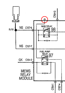
The internal wiring of the MFRU shown on the EU2
diagram is actually for the EU3 MFRU, which is not compatible with the EU2
loom. It shows the fuel pump relay being supplied from a pin which is not
connected (see below). Interestingly this is actually the exact situation which
occurs if you try to use an EU3 MFRU in an EU2 loom
and the fuel pump does not run. An EU2 MFRU may
however be used in an EU3 loom without issues.
2.
The diagnostic plug was incorrectly drawn,
showing the plug viewed from the wrong side.
3. Most of the connectors were drawn as simple rectangular blocks with no information on pinout and orientation.
4. The diagrams in circulation are poor quality scanned images of hand drawn diagrams originally printed in the Assembly Guide. They are in many cases barely legible and difficult to follow. The layout is convoluted and the VVC and non-VVC diagrams are drawn completely differently, making it very hard to see the commonalities between them. In reality much of the wiring is the same across both engines.
5. No part numbers or sources are shown for any of the connectors. Although many are standard series connectors, some such as the ECU plugs and engine loom to injector loom headers are more difficult to identify. Rover part numbers are now of little use - OEM part numbers are required.
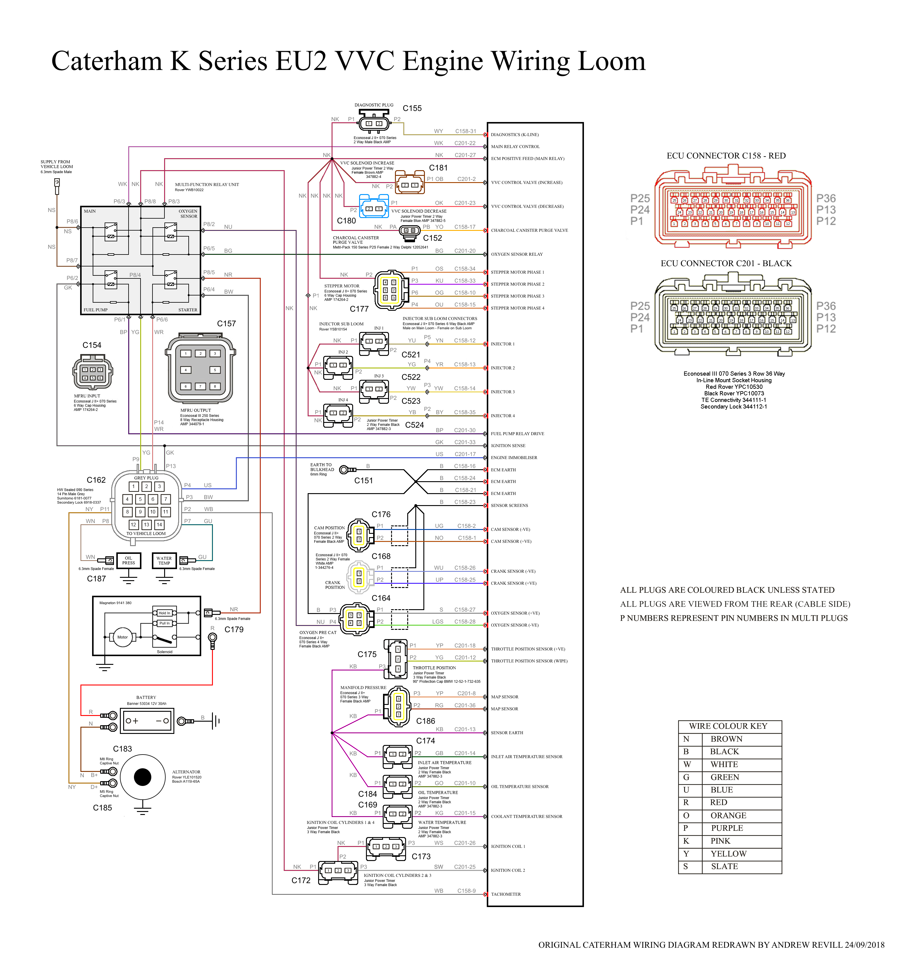
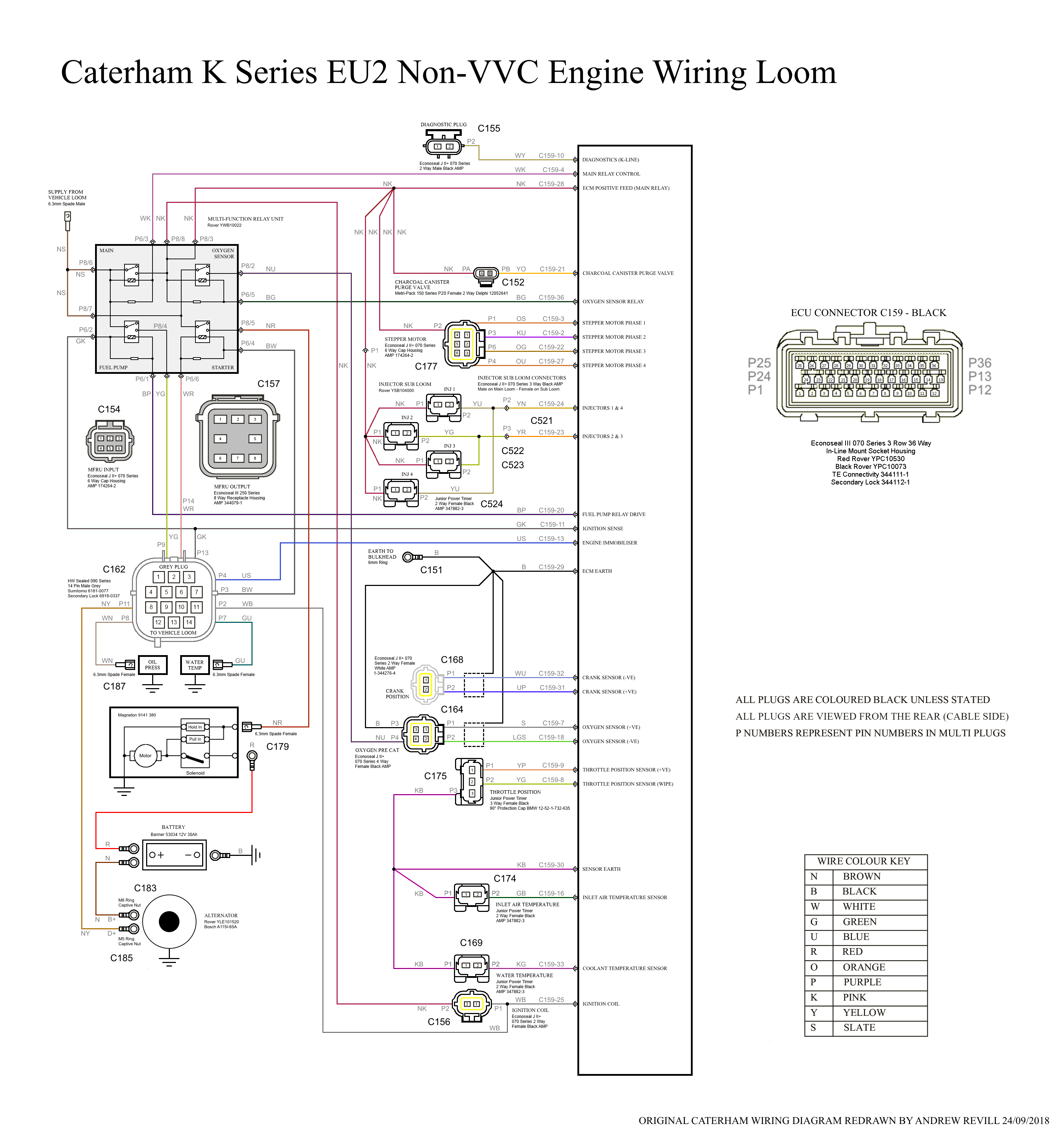
I have therefore completely reworked the wiring diagram to address all of the above and wanted to share it back to the club membership as I felt others may find it useful, as I did with the EU3 diagram.
As I do not own an EU2 car I haven’t been able to cross-check it to the same extent as I did with the EU3 diagram, but I have corrected the known errors and drawn it in a clear logical layout. Most of the information is taken from the original diagrams sense-checked and cross-referenced to Rover’s published diagram for the MGF.
As there are only two diagrams, one for the VVC engine and one for the non-VVC engine, I have
Download Links:
1. All of the known errors have been corrected. If anyone does spot any errors or omissions, please let me know and I'll be happy to try to keep this up to date as a reference.
2. I have tracked down OEM and part numbers for each of the connectors. Please be aware that with some connectors e.g. the multi-pin ECU plugs, there are other connectors which look almost identical but have slightly different terminal sizes etc. The part numbers shown are believed to be correct.
3. Wire colours are shown for every wire.
4. On my diagram ALL CONNECTORS ARE DRAWN VIEWED FROM THE WIRING SIDE, NOT LOOKING AT THE CONNECTOR FACE. This was primarily because I drew the diagram for the purposes of constructing or modifying a loom and this was the most useful view for me, however it is different to the convention (mostly) used by Caterham in other diagrams. It is at least consistent throughout.
5. PLEASE NOTE THAT THIS DIAGRAM APPLIES TO EU2
K SERIES ENGINES ONLY.
I hope this is of use to people. Please feel free to feed back comments and corrections which I will endeavour to incorporate into the diagram as and when I get the time.