Adding VVC to an EU3 K Series Engine Wiring
Loom
Several people have contacted me over the last couple of years to
ask about the wiring changes needed when replacing a standard K Series engine
with a VVC engine. The VVC engine has additional sensors and actuators and a
different type of cam position sensor so changes are required to the wiring
loom. Alan Archer asked me to help him do such a conversion recently so I
decided to write up the whole conversion process as a detailed guide. The
information below relates specifically to EU3 (Coil-On-Plug) engines as the
earlier EU2 engines were wired very differently. It is therefore applicable to
anyone who has an EU3 K Series engine and wants to
replace it with a VVC 160. I have described in detail with pictures and
diagrams how to add the VVC solenoid and oil temperature sensor wiring and how
to modify the cam position sensor wiring.
Alan had one particular requirement; he wanted to be able to
switch the wiring loom back to MPi configuration if he ever wanted to sell the
car but retain the VVC 160 engine. The changes below are therefore done in such
a way that alternative sub-looms may be connected to an adapter connector to
allow the main loom to be used with both MPi and VVC style cam sensors (the
other additional VVC wiring would simply be folded up and left disconnected
when used with an MPi engine). Where this requirement is not applicable, the
loom design may be simplified a little and the separate sub-loom for the cam
position sensor can just be wired directly into the main loom omitting the
adapter connector if desired.
VVC-Only
Loom: The vast majority of the procedures described would
remain unchanged. Where applicable I have highlighted the differences in the
comments in blue.
I have divided this article up into the following sections:
·
In Theory – In
which I show the wiring diagrams and discuss what we are trying to achieve.
·
In
Practice – In which I show in detail the actual process of modifying the loom
with pictures.
·
Installation – In
which I show the correct installation of the VVC connectors.
·
Connector
Pinouts – In which I show pictures of every connector showing which wires
are connected to which pins.
·
Parts List – In
which I list the parts required to complete the modification with part numbers,
links etc. This includes details of the connectors used and the corresponding
terminals and wire seals.
In Theory
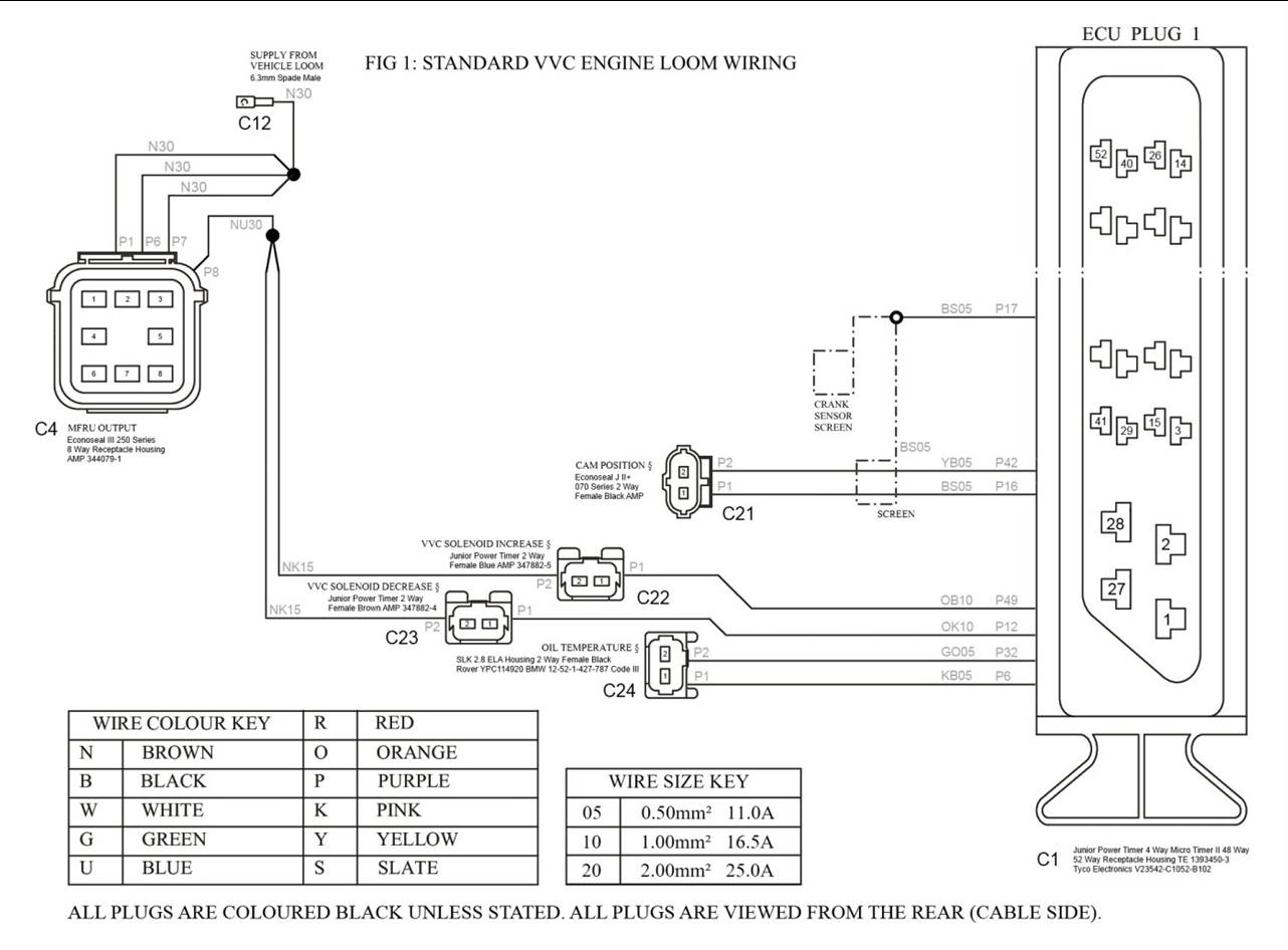
The wiring diagram FIG 1
is an extract from the Caterham K Series EU3 Engine Loom wiring diagram. Note
that the original Caterham wiring diagram shows the cam positon sensor wired
incorrectly. The diagrams below have these errors corrected. This diagram shows
wiring we are interested in as configured in the standard loom for a VVC
engine.
It shows the wiring for the cam position sensor and its associated
screening (which is common to the screening used for the crank position sensor)
plus the solenoids which operate the VVC mechanism and the oil temperature
sensor on the VVC HCU which the ECU uses to predict the rate at which the VVC
mechanisms will respond. The solenoids are powered from a main common power
supply within the loom; wiring for this from the MFRU is also shown.
This is configuration we are aiming to replicate.
FIG 1:
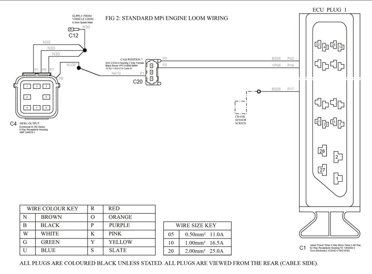
The wiring diagram FIG 2
shows wiring we are interested in as configured in the standard loom for an MPi
engine.
This is configuration we are starting from.
You will see that there are a number of differences. Firstly, all
of the VVC solenoid and oil temperature sensor wiring is missing completely.
Secondly the cam position sensor wiring is different; although connected to the
same ECU pins the wire colours are different, it uses a different connector,
the wires are actually too short to reach the physical position of the sensor
and it has a power supply wire which we don’t need but more importantly the
wiring is not screened. The MPi engine uses a Hall Effect sensor which contains
in internal amplifier and therefore needs a power supply and produces a high
level, low impedance signal. The VVC engine uses a passive Variable Reluctance
sensor (almost identical to the crank position sensor) which produces a low
level, high impedance signal which is very prone to interference pickup in the
wiring. It is therefore important to correctly screen the signal cables on the
VVC engine, as is done for the crank position sensor on all engines.
FIG 2:
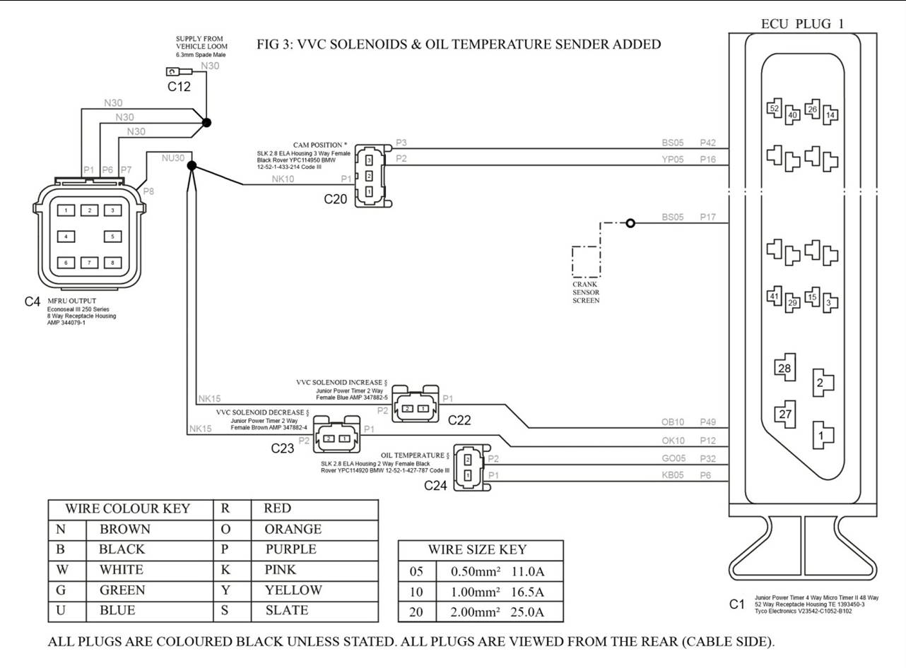
As shown in FIG 3, the
first step in modifying the loom will be to add in the missing wiring for the
VVC solenoids and oil temperature sensor.
FIG 3:
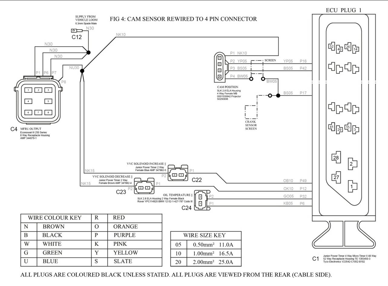
As shown in FIG 4, we
will then modify the cam position sensor wiring. The plan is to wire it to a 4
pin connector which will contain the original 3 wires for the MPi sensor plus a
screen connection. We will add screening to the signal wires by tapping into
the screening for the crank position sensor at the ECU and connect the other
end of the screen to the fourth pin of the connector.
FIG 4:
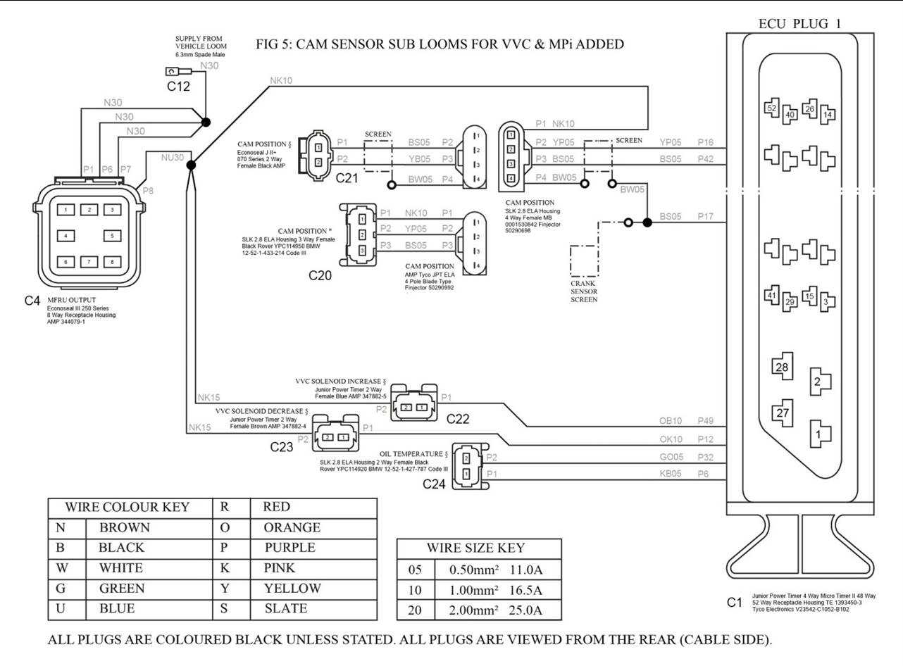
As shown in FIG 5, this
will then allow us to plug one of two small sub-looms into this adapter connector,
allowing the loom to be used with either MPi or VVC engines. Each sub-loom will
connect to only 3 of the 4 pins in the adapter. The VVC sub-loom will connect
to the two signal pins and will use screened cable, with the screen chained
onto the screen pin. The power supply pin will be left unconnected. The MPi
sub-loom will connect to the two signal pins and the power supply pin using
unscreened cable.
FIG 5:
As shown in FIG 6, if
the ability to use the loom with an MPi engine was not needed, this could be
simplified a little. There would be no need to wire in the cam sensor power
supply and the adapter connector could be omitted entirely. Rather than
terminating the signal wires and screen at the adapter connector they would
simply be extended straight to the cam position sensor connector. Everything
else would remain the same.
FIG 6:
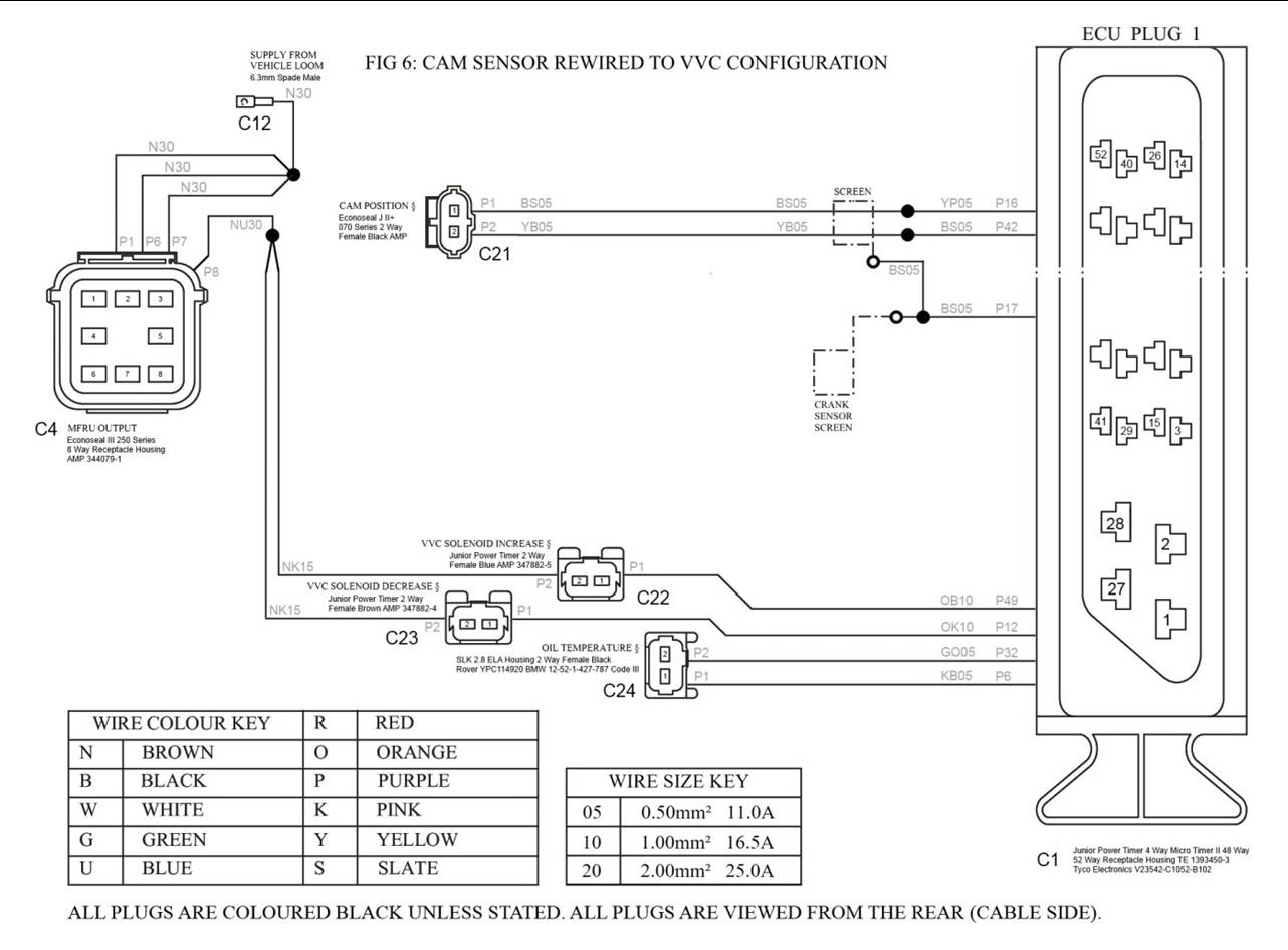
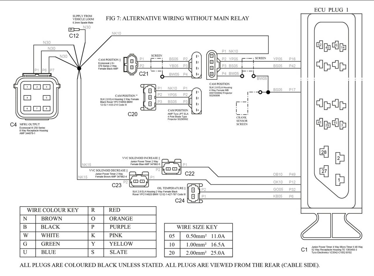
FIG 7 shows the
alternative power supply wiring found on some cars. The wiring diagrams in FIG 1 to FIG 6 all assume that Main Relay inside the MFRU is used. This
relay allows the ECU to switch on and off the power supply to the various
actuators and sensors to reduce leakage and consequent battery drain when the
engine is not running. This relay switches power supplied to pin 6 of the MFRU
output plug out to pin 8. Some wiring looms do not connect the Main Relay. In
these cases those items which would otherwise be on the switched power supply
are connected to the unswitched power supply directly. In order to determine
which way your car is wired, look at pin 8 of the large output plug on the MFRU
(black box that sits on top of the ECU, bottom right hand pin as viewed from
the wiring side). If this has a thick wire, usually Brown/Blue, the Main Relay
is used and your wiring matches the diagrams in FIG 1 to FIG 6. This
wire is the one which should be tapped to provide power supplies for the VVC
solenoids as described in FIG 27 and
FIG 28. If this pin is unused, the
Main Relay is unused and your wiring matches the diagram in FIG 7. The thick wire from pin 6 is
then the one which should be tapped instead.
FIG 7:
In Practice
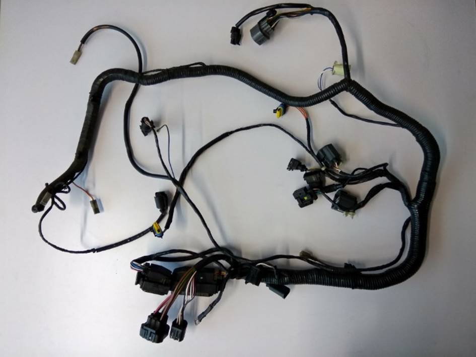
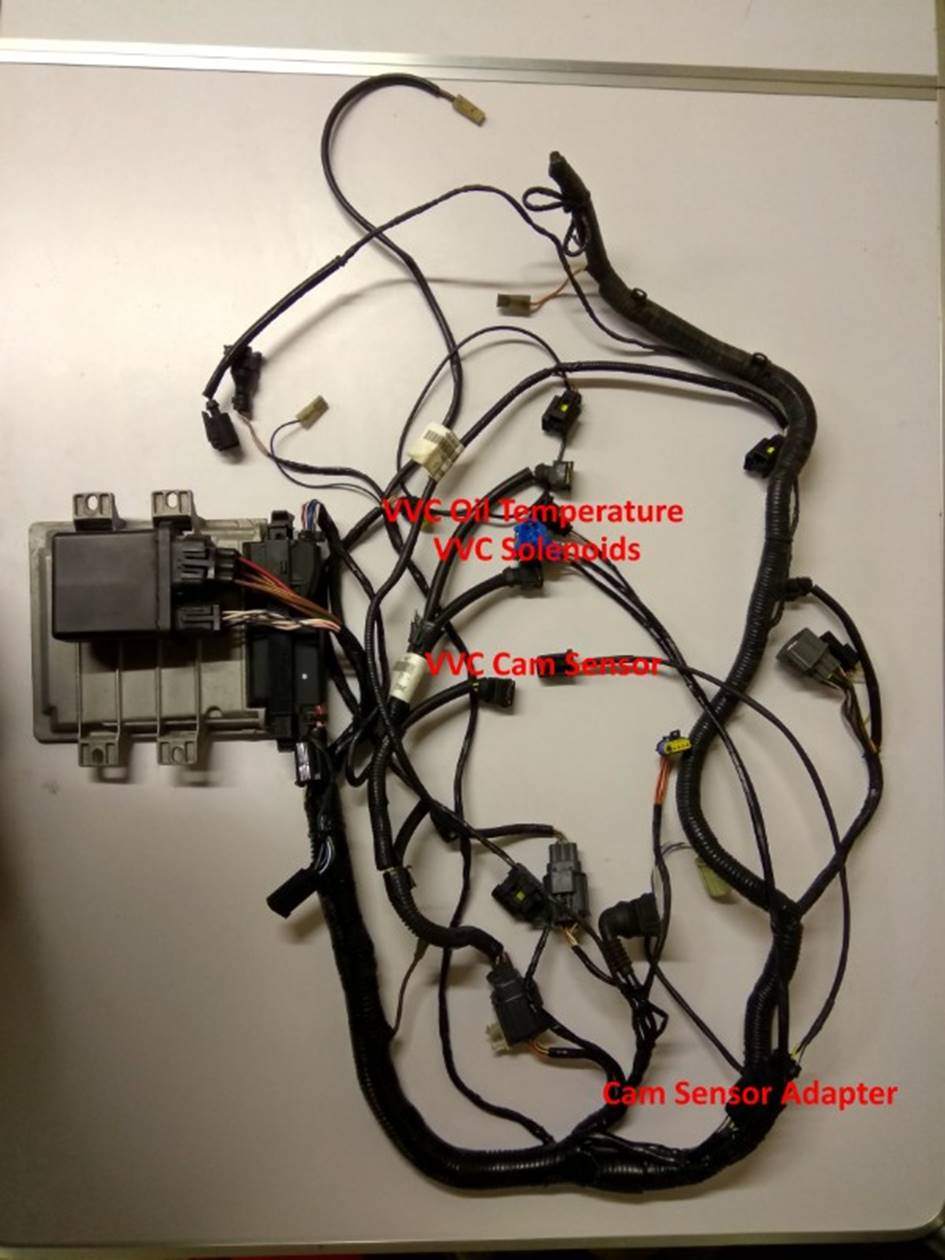
FIG 8 shows a
picture of the MPi engine loom as removed from the car. To remove the loom it
is necessary to disconnect all connectors and cut the numerous cable ties which
attach the loom to the vehicle. The earth connector for the loom may consist of
an eyelet bolted to the bulkhead. The loom may also contain a metal guide shoe
which may be bolted to the front of the oil pump to guide the loom safely under
the crank pulley. If you are not familiar with which connector goes where and
the correct routing of the loom, take lots of photographs as you remove it and
label the connectors.
FIG 8:
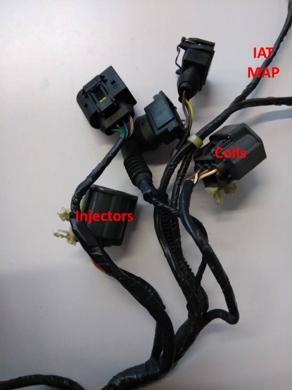
This particular loom is the slightly more unusual Powertrain-Yasaki
type loom. This has separate sub looms for the injectors and coil packs. The
connector for the combined IAT and MAP sensor on the front end of the plenum
chamber is part of the main engine loom. As shown in FIG 9 the main engine loom therefore has separate Yasaki-type
connectors for the injector and coil sub looms and a long spur for the IAT/MAP
sensor.
FIG 9:
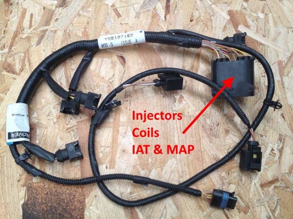
More commonly there will be a single sub-loom for the injectors,
coils and IAT/MAP sensor as shown in FIG
10. The engine loom will therefore have a single large multi-pin connector
which connects to this sub loom and no spur for the IAT/MAP sensor. For the
purposes of this article both types of loom are pretty much identical and the
differences identified do not impact upon the changes we need to make; however
on a standard loom there may be slight internal construction differences when
comparing to the photographs shown here.
FIG 10:
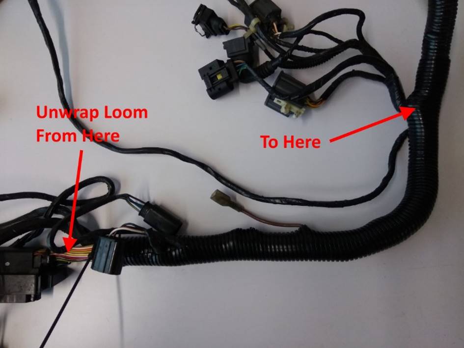
The first thing we need to do once the loom is removed from the
vehicle is to carefully remove the various layers of tape and split convoluted
tubing from the area of the loom we need to work on as shown in FIG 11. There will typically be layers
of tape around the wires themselves followed by pieces of convoluted tubing and
an outer layer of tape to keep the convoluted tubing in place. Be very careful
not to damage any wires while removing the coverings. Keep the pieces of
convoluted tubing on one side as they may be used again on reassembly.
FIG 11:
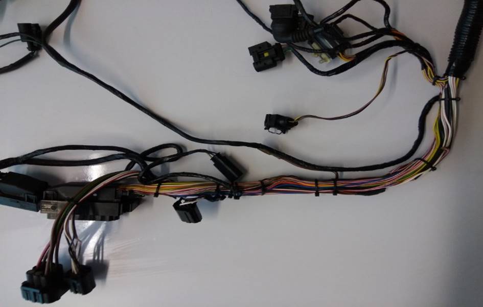
Use temporary cable ties to hold the loom together as you unwrap it as shown in FIG
12. Cable ties each bundle of cables separately at each point where the
loom divides or cables exist from the loom. As you add wires into the loom
later you will need to cut and replace these ties so it is worth getting hold
of a large packet of them before starting. The ties should all be removed as
the loom is taped up again on completion. You will see in FIG 12 that I have also unwrapped the wiring to the cam position
sensor.
FIG 12:
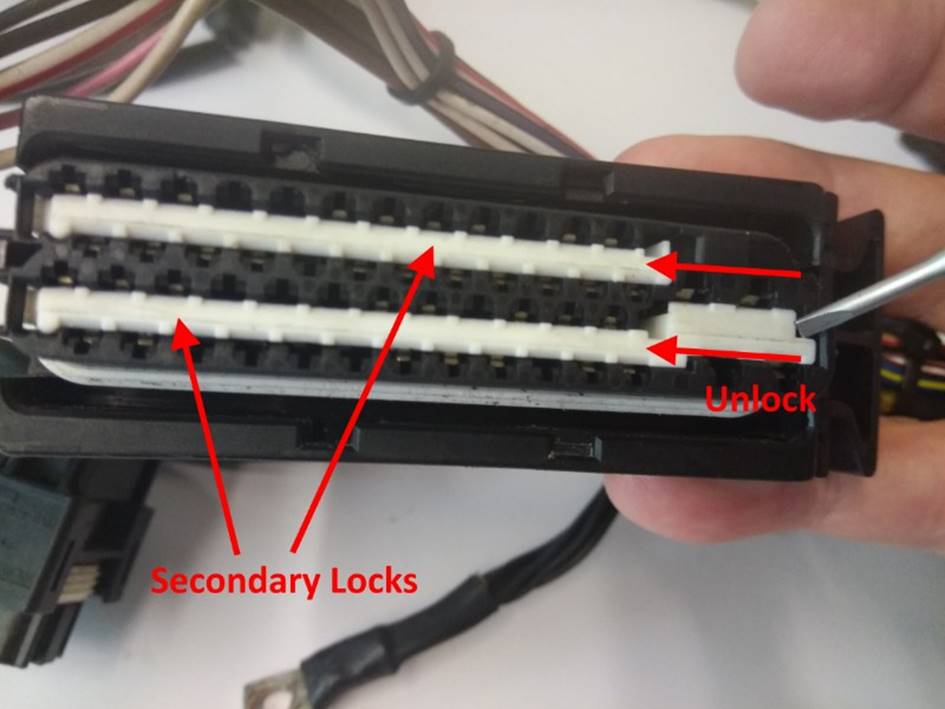
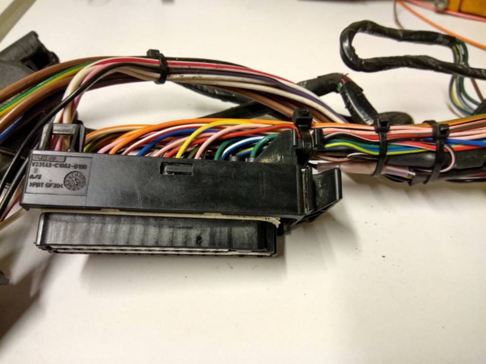
The next thing to do is to unlock the terminals in the ECU
connector. We only need to make changes to the larger of the two ECU connectors
as shown in FIG 13; the other
connector does not need to be disturbed. The two white plastic portion shown
are secondary locks which firmly lock the terminals into the connector housing.
There are two secondary locks, each one locking two of the four rows of
terminals. They are shown in the locked position. In order to be able to add
new terminals into this connector we need to unlock both of them. To do this,
push them firmly in the direction shown with a screwdriver. The will click
across into the unlocked position. In the unlocked position the connector will
not fit onto the ECU, so when you have finished adding terminals to this
connector the secondary locks must be clicked back into the locked position by
pressing on their opposite ends.
FIG 13:
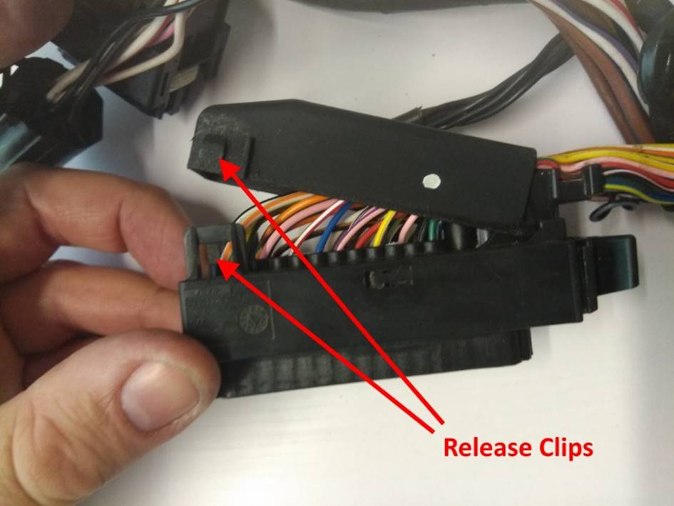
We now need to remove the back shell of the connector. This is
done by releasing the two clips, one on either side of the connector, then
pivoting the shell upwards to unhook it at the other end as shown in FIG 14. Be careful because the portions
of the clips attached to the main connector housing can become brittle over
time and will snap if levered back too far. It can be tricky to get both clips
unclipped at the same time.
FIG 14:
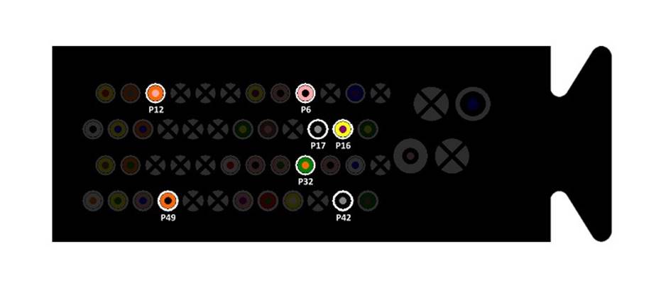
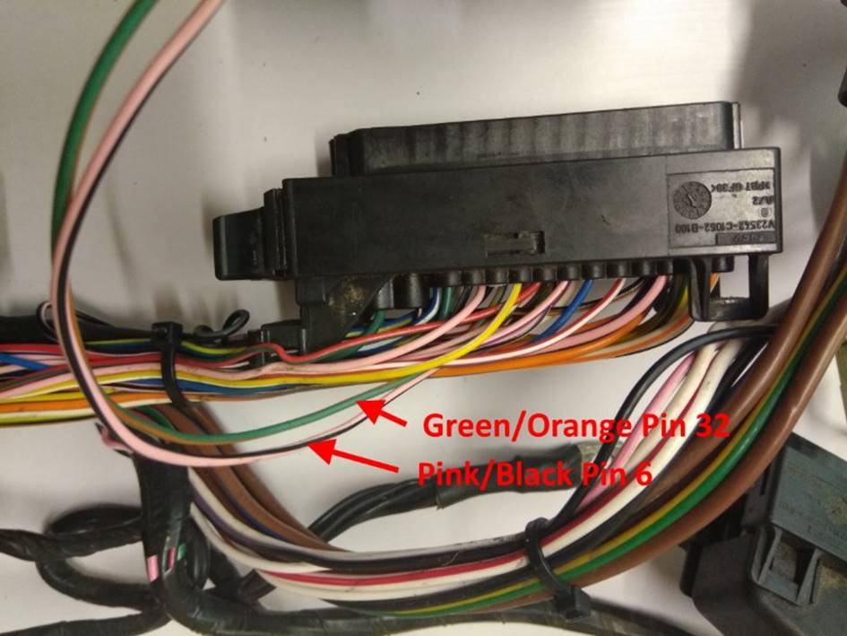
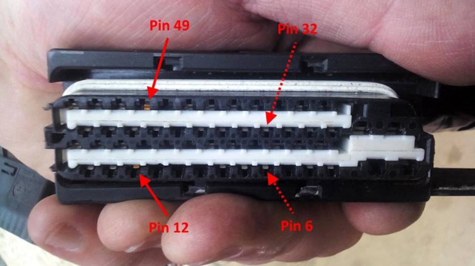
On this loom I was surprised to find that the two pins associated
with the VVC oil temperature sensor were already present and connected to wires
of the correct colours. These are the Pink/Black wires and Green/Orange wire
show connected to pins 6 and 32 in the connector pinout diagram FIG 15. On your loom, these pins may or
may not be present. If not present, you can install new pins and wires as described
in FIG 19 to FIG 25 for pins 12 and 49. On this loom I had to set about tracing
where the other ends of these wires were connected.
FIG 15:
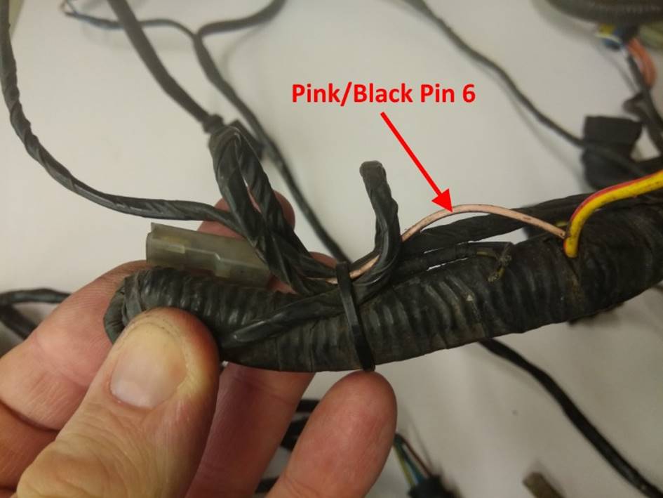
The Pink/Black wire from pin 6 was traced to a redundant unused
spade connector at the end of the loom close to the oil filter housing (which
made sense if it may have been intended to connect to another oi temperature
sensor on the housing) as shown in FIG
16. To avoid having to strip the remaining portion of the loom, this wire
was simply cut short where it entered the wrapped portion of the loom. The tail
with the spade connector was also cut off to avoid confusion as it was no
longer connector.
FIG 16:
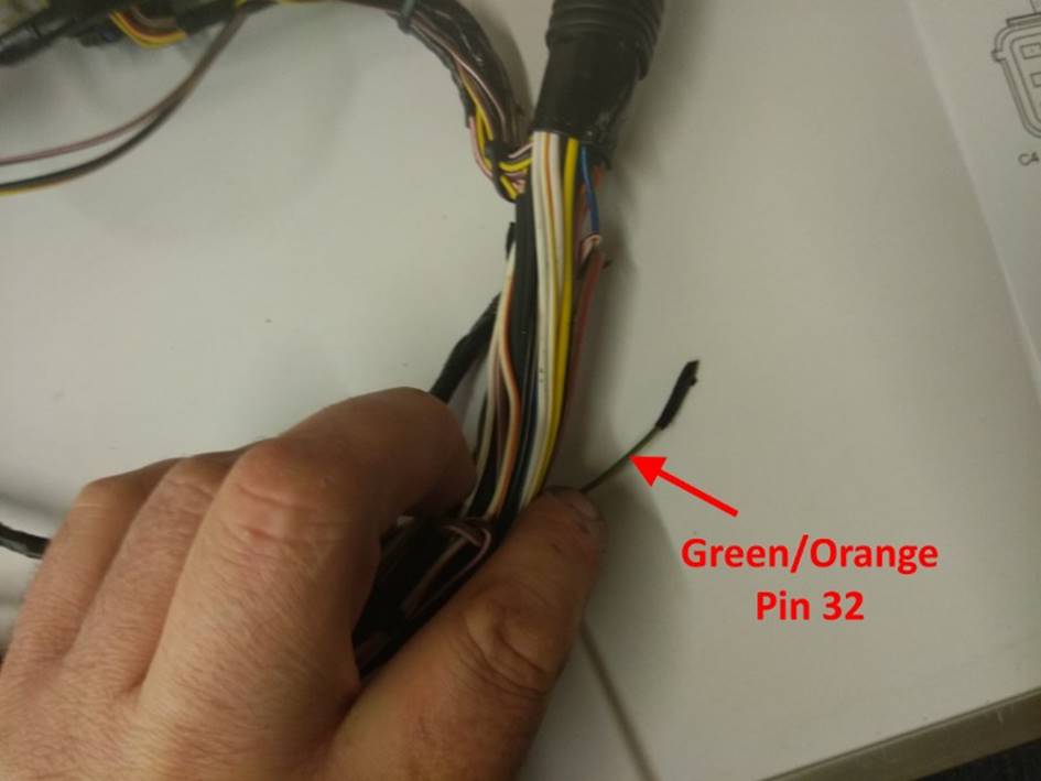
The Green/Orange wire from pin 32 was found to simply terminate
inside the loom unconnected and wrapped in tape at the same point where I had
cut back the Pin/Black wire as shown in FIG
17.
FIG 17:
I then carefully released the two wires from the loom right back
to the ECU connector as shown in FIG 18.
This would allow me to re-use the pins in the ECU connector by splicing my own
wires of the required length onto these wire tails. As mentioned in the notes
for FIG 15, if either of these wires
are not already present, you can install new pins and
wires as described in FIG 19 to FIG 25 for pins 12 and 49 rather than
splicing onto the tails of the existing wires. You could also remove the
existing pins and wires entirely, however removing terminals from this
connector can be difficult and can damage the plastic locks that the terminals
hook onto meaning that the new terminals don’t lock into place properly so I
chose not to disturb them.
FIG 18:
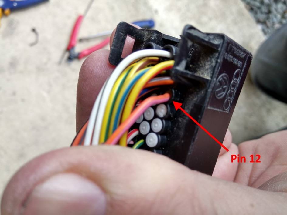
The next task is to add in the two new wires and terminals for the
VVC solenoids. Each unused terminal position in the ECU connector will have a
white blanking plug installed to keep the connector waterproof overall. It is
necessary to carefully prise out the blanking plugs associated with pins 12 and
49. These can be hooked out from the back of the connector with a needle. In
the end I found the easiest way was actually push the end of a small cable tie
into the corresponding pin hole from the front of the connector to push the
blanking plug out of the back. FIG 19
shows the correct position corresponding pin 12.
FIG 19:
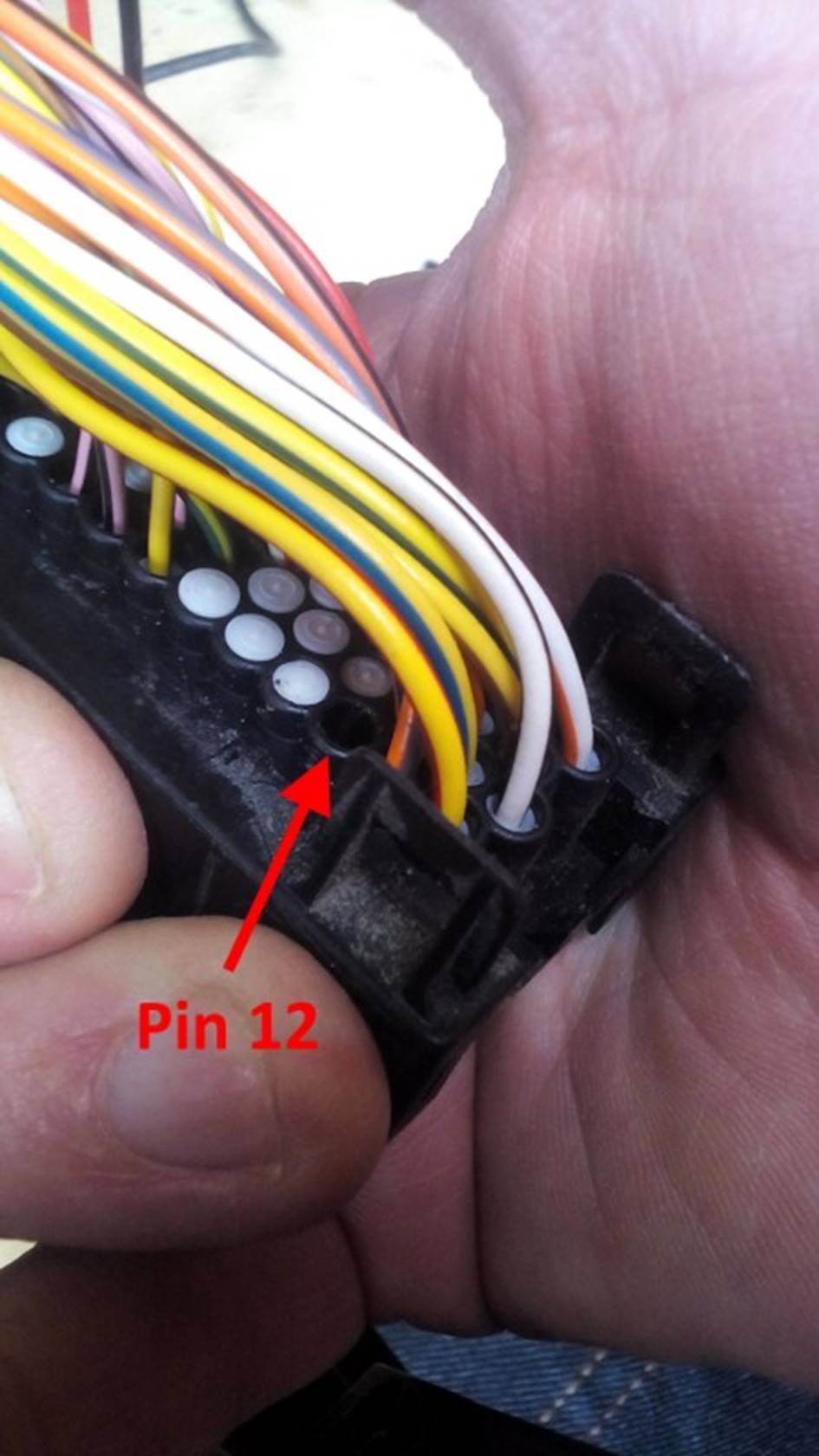
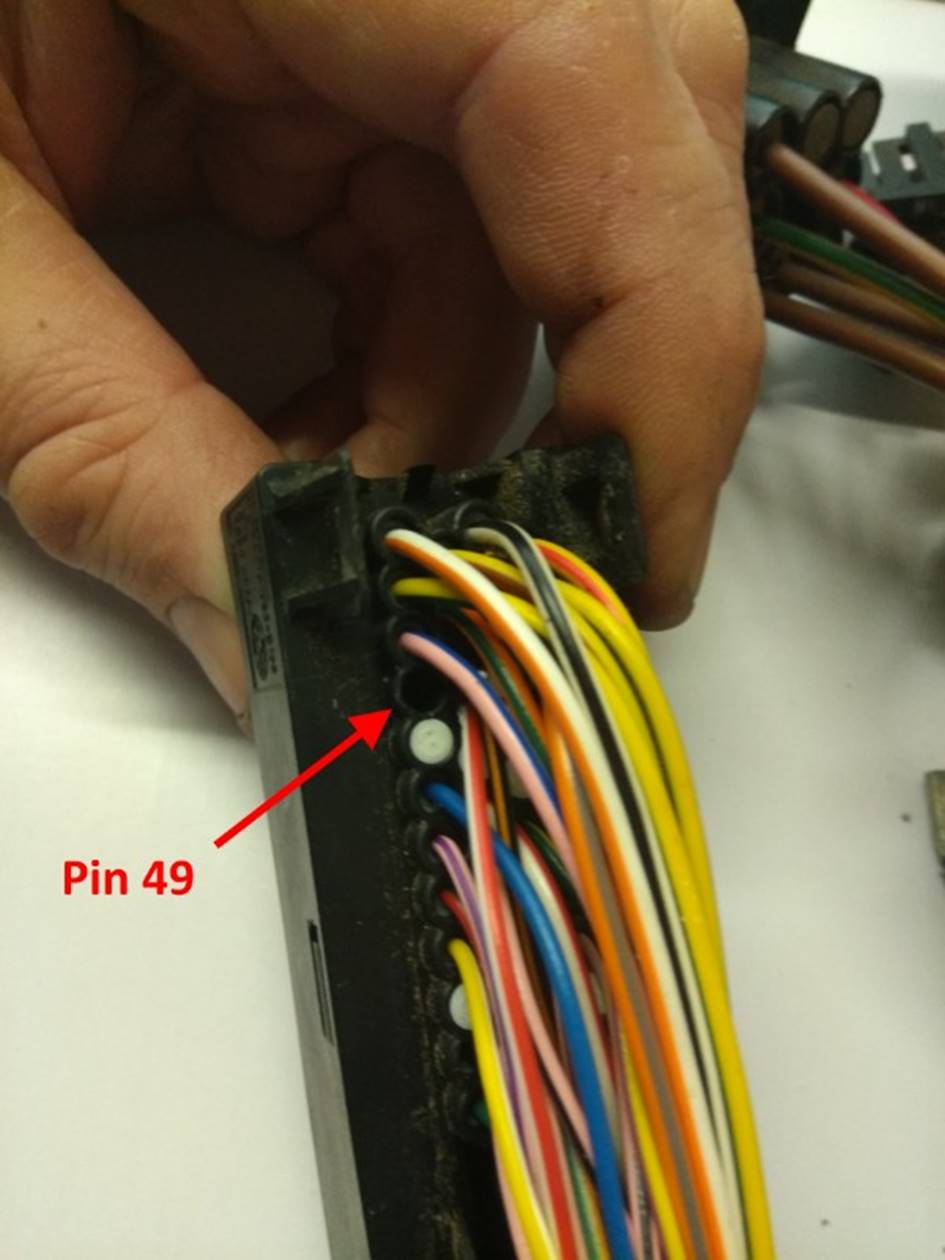
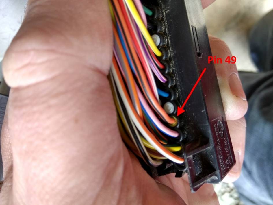
FIG 20 shows the
correct position corresponding pin 49. Check very carefully at this point that
the correct two blanking plugs have been removed by comparing with these
photographs and the ECU connector pinout shown.
FIG 20:
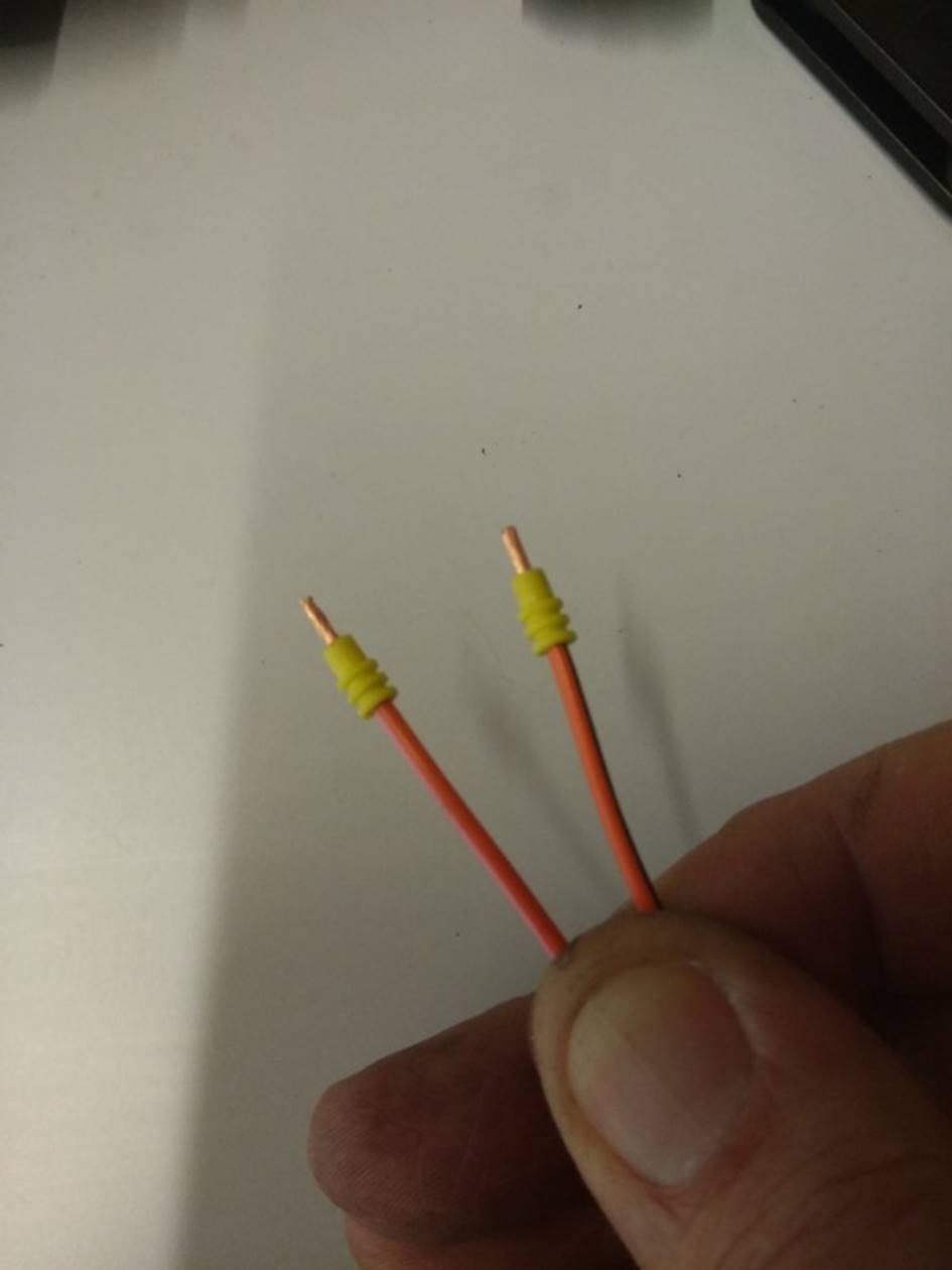
The new wires to be inserted should now be fitted with wire seals
and terminals. The seals and terminals required are Micro Timer II. And need to
be installed using a proper and suitable F-type ratchet crimping tool. The
seals should be pushed onto the wires first, then approximately 6mm of
insulation should be stripped and the seals slid back up the wires until they
align with the ends of the insulation. There is no need to twist the cut wire
ends but it is important to ensure the strands lie together in a neat bundle,
which can be achieved by a very gentle twisting with the fingers as shown in FIG 21.
FIG 21:
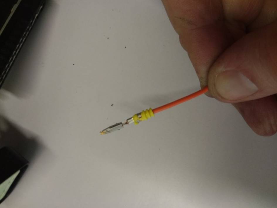
The terminals are then crimped onto the stripped ends of the
wires, clamping the seals as shown in FIG
22. If the terminals are significantly distorted by the crimper or if the
wire, seal and terminal do not end up correctly aligned with each other it is
best to cut the terminal off and try again with a new terminal and seal. It
should be possible to pull the terminal firmly without it coming off the wire.
It is best to order more terminals and seals than needed to allow for failures.
FIG 22:
The crimped terminals are the clicked into the appropriate
positions in the ECU connector housing. Be very careful to ensure that the
correct wire is inserted into the correct position as shown in the FIG 23 and FIG 24 as they can be very difficult to remove without permanently
damaging the housing. The correct orientation of the pins can be judged by
looking at the existing pins from the front of the connector. The Orange/Pink
wire terminal is installed in position 12 as shown in FIG 23.
FIG 23:
The Orange/Black wire terminal is installed in position 49 as
shown in FIG 24.
FIG 24:
When viewed from the front of the connector, the new terminals
should be visible in the positions shown in FIG 25. As the terminals I used for pins 12 and 49 were gold plated
and the standard terminals are tin plated, the new terminal positions stand
out. If new terminals are also being installed for pins 6 and 32 they should
appear in the positions shown in FIG 25.
In this case, these pins were already present.
FIG 25:
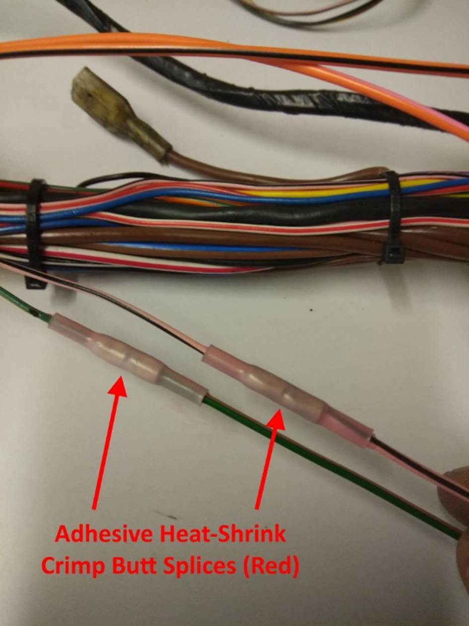
Once the new terminals have been installed, the existing oil
temperature wires can be extended. Cut the wires off such that the spliced
joints will lie in a straight portion of the loom and cut them to slightly
different lengths so that the spliced joints are staggered so that they lie
neatly within the loom when it is taped up again as shown in FIG 26. At this stage, leave all of the
wires longer than required. Once they have been routed through the loom to the
relevant connectors it is much easier to judge how long they need to be. I used
adhesive lined heat-shrink butt splice connectors. These are much better than
the regular insulated crimp terminals, which are inappropriate with the loom.
Before heat-shrinking, pull firmly on the spliced wires to ensure that they are
crimped securely. Once shrunk with a heat gun, the adhesive melts and seals the
joint and provides mechanical support and the finished splices are small and
neat. These splices are available in three standard sizes coded red, blue and
yellow. The smallest red splices are appropriate here. Although the existing
wiring and the wiring diagram use 0.5mm² cable here,
in order to obtain the correct colour combinations I was forced to use 1mm²
cable. You can see in the picture that the extension cables on the right are
slightly thicker than the existing cables on the left. It is always permissible
to use a thicker cable in place of a thinner cable (within reason), but not the
other way around.
FIG 26:
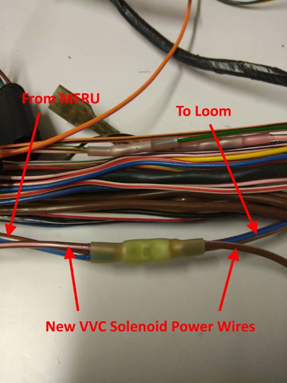
The next step is to tap into the power supply wiring within the
loom to take off new supply wires for the VVC solenoids. Which wire you need to
tap into here depends on the way in which your loom is wired, as described in
the notes for FIG 7. In order to determine which way
your car is wired, look at pin 8 of the large output plug on the MFRU (black
box that sits on top of the ECU, bottom right hand pin as viewed from the
wiring side). If this has a thick wire, usually Brown/Blue, the Main Relay is
used. This wire is the one which should be tapped to provide power supplies for
the VVC solenoids as shown in FIG 27
and FIG 28. If this pin is unused,
the Main Relay is unused. The thick wire from pin 6 is then the one which
should be tapped instead. Once the correct wire has been identified and a
convenient point to tap into has been identified, the wire is cut and spliced
back together using a large yellow heat-shrink butt splice crimp. Before
crimping, one of the VVC solenoid supply wires is inserted into each end of the
crimp as shown in FIG 27. The main
power supply wire is 3mm² and the VVC solenoid wires are specified as 1.5mm²
although 2mm² is more readily available. Care must be taken that both wires are
securely held by the crimp at each end to ensure a reliable connection. It may
be necessary to strip a little more insulation than is usually required from
each wire. Ensure that the stripped ends in each pair of wires are the same
length and that each wires is fully inserted into the crimp to the same extent.
If it proves difficult to align the two wires, it may help to tie them together
with a couple of small temporary cable ties, allowing them to be aligned
correctly. The stripped ends can then be very lightly twisted together to form
a single bundle before inserting into the crimp. After crimping and before heat
shrinking, pull the wires firmly to ensure that they are secure. When applying
a heat gun it may be prudent to slip a piece of cardboard or similar between
the wires being spliced and the rest of the loom to protect the other wires
from the heat. Once shrunk with a heat gun, the adhesive melts and seals the
joint and provides mechanical support. At this stage, leave all of the wires
longer than required. Once they have been routed through the loom to the
relevant connectors it is much easier to judge how long they need to be.
FIG 27:
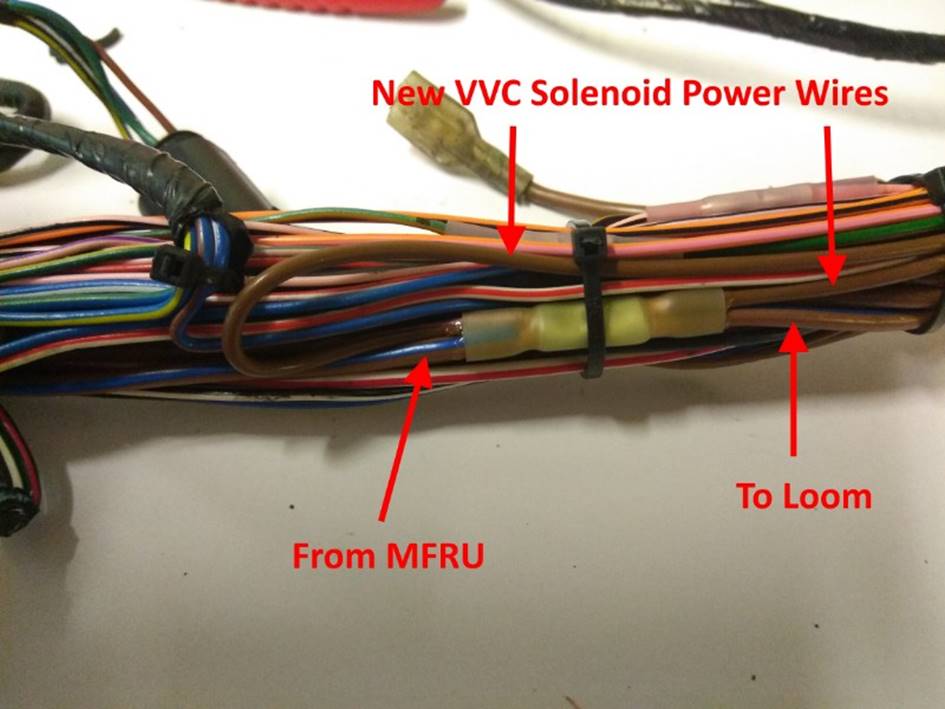
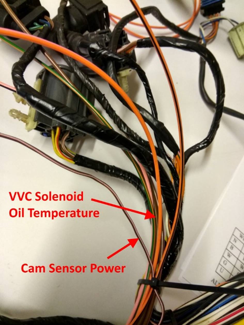
Once the spliced joint has been made, the two new power wires can
be routed neatly away from the ECU and tied into the loom as shown in FIG 28. In this picture you can see all
of the new spliced joints for both the VVC solenoids and the oil temperature
sensor.
FIG 28:
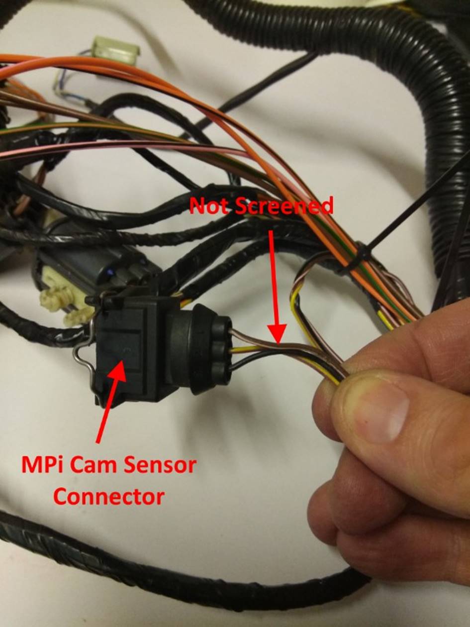
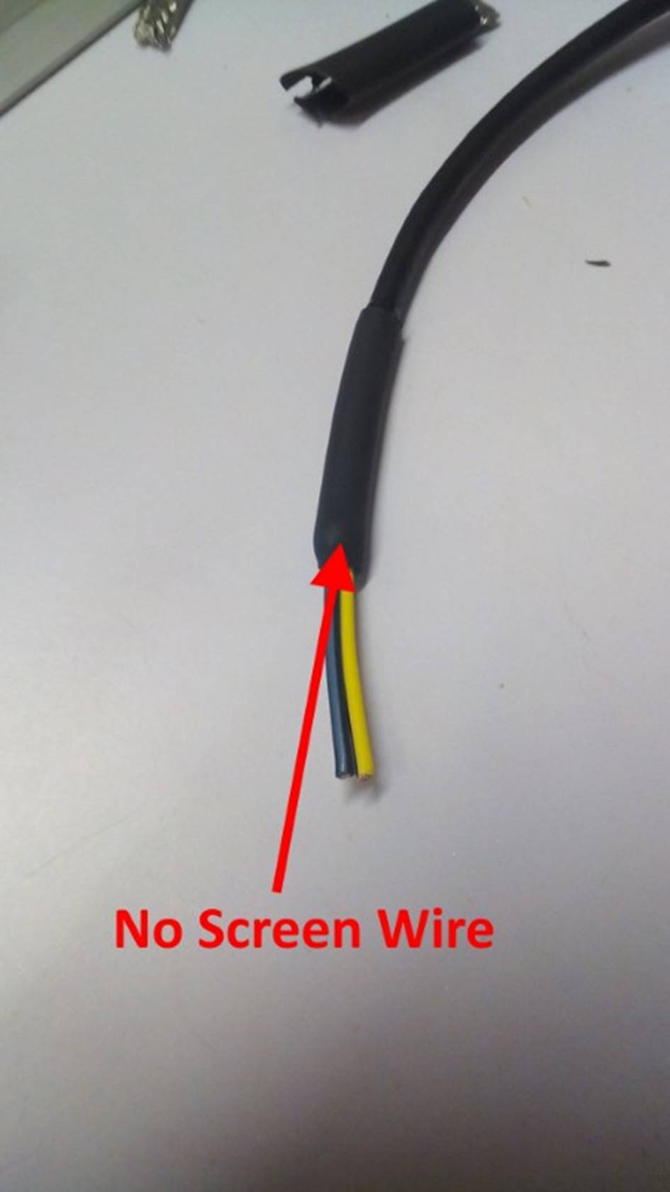
Attention now turns to the cam position sensor wiring. As the
wiring for the MPi sensor is not screened as shown in FIG 29, we need to unravel it from the loom right back to the ECU
to allow screening to be added. The wires can be cut close to the connector. I
would recommend using a new plug for the MPi sub-loom, however if the existing
connector and terminals are to be reused, leave enough of a wire tail on it to
allow the wires to be spliced but don’t cut the wires in the loom shorter than
necessary at this stage.
FIG 29:
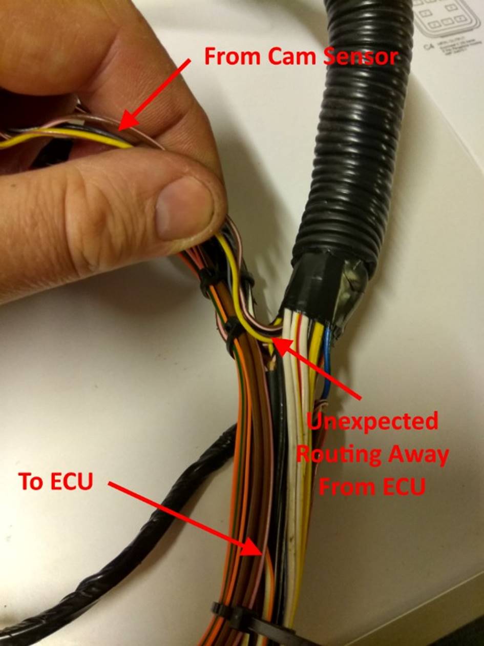
On this loom, as I traced and unravelled the wiring I was
surprised to find that disappeared into the wrapped portion of the loom rather
than running towards the ECU as expected, as shown in FIG 30.
FIG 30:
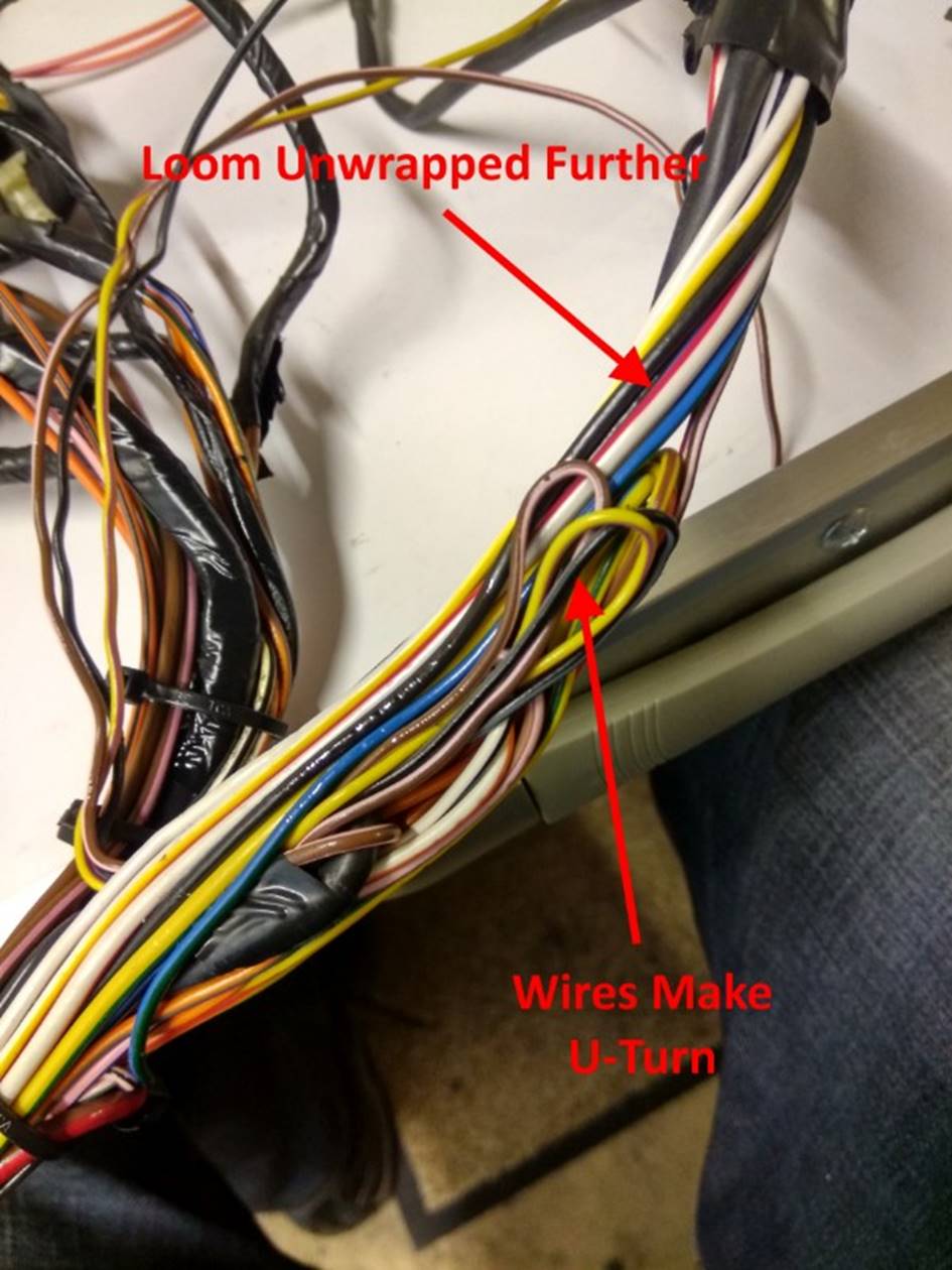
I was therefore forced to unwrap the loom
a little further to investigate and found the wires simply did a U-turn back
towards the ECU as expected as shown in FIG
31. You loom may or may not be constructed in this
way.
FIG 31:
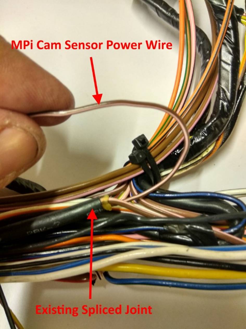
The power supply wire for the cam sensor was found to be spliced
very close to the point where I wanted to route it out of the loom to the
adapter connector, as shown in FIG 32.
FIG 32:
It was therefore carefully routed out of the loom alongside the
other bundle of cables that branched from the loom at this point, as shown in FIG 33.
VVC-Only
Loom: Where there is no requirement to be able to use the
loom with an MPi engine, this power supply wire is not required. It can be cut
off short, insulated and taped into the loom for neatness.
FIG 33:
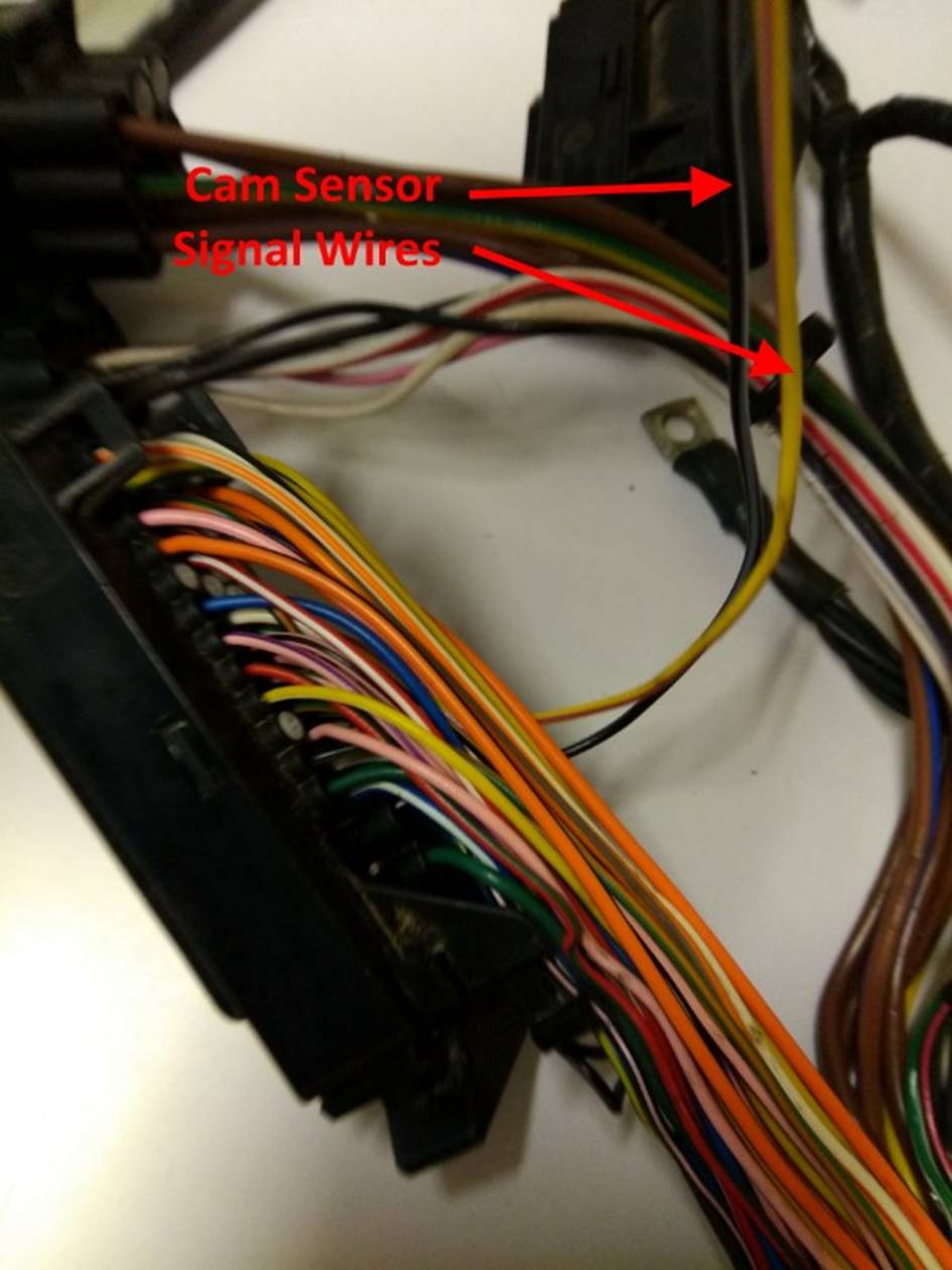
The two cam sensor signal wires were then unravelled and separated
right back to the ECU connector, as shown in FIG 34.
FIG 34:
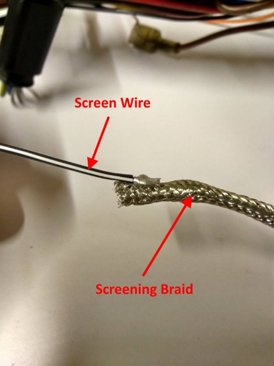
The next job is to add a screen to the cam sensor signal wires.
The screen is made from tinned copper braided tube. In order to connect to
this, a short length of Black/White wire is carefully soldered to the end of a
length of braid as shown in FIG 35.
Although the existing screen wires within the loom use Black/Slate wire, to
avoid any possible confusing Black/White wire was used as one of the signal
wires is also coloured Black/Slate.
FIG 35:
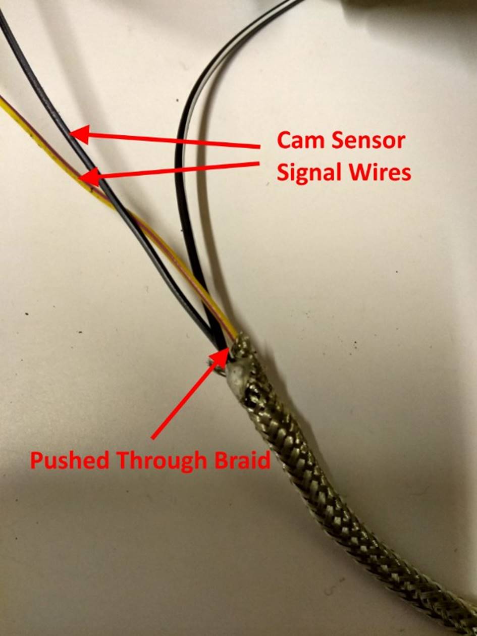
After soldering, the two signal wires are then fed carefully along
the braided tube, as shown in FIG 36.
FIG 36:
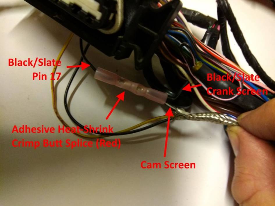
It is now necessary to identify the existing Black/Slate wire from
pin 17 of the ECU connector which connects to the screen on the crank position
sensor wiring. On this loom this wire conveniently formed a loose loop adjacent
to the ECU connector which was easy to cut and splice. On other looms this may
not be so easily accessible so care should be taken to think of the best way to
tap into it. In this case I was able to cut the wire and splice it back together
with a small red heat-shrink butt splice crimp, feeing the new Black/White
screen wire into one end of the crimp as shown in FIG 37. Keep the screen connections as short as possible, although
there is no need to make them quite as short as I did here. Again, once crimped
give the wires a firm pull to ensure that they have been securely crimped
before applying the heat gun.
FIG 37:
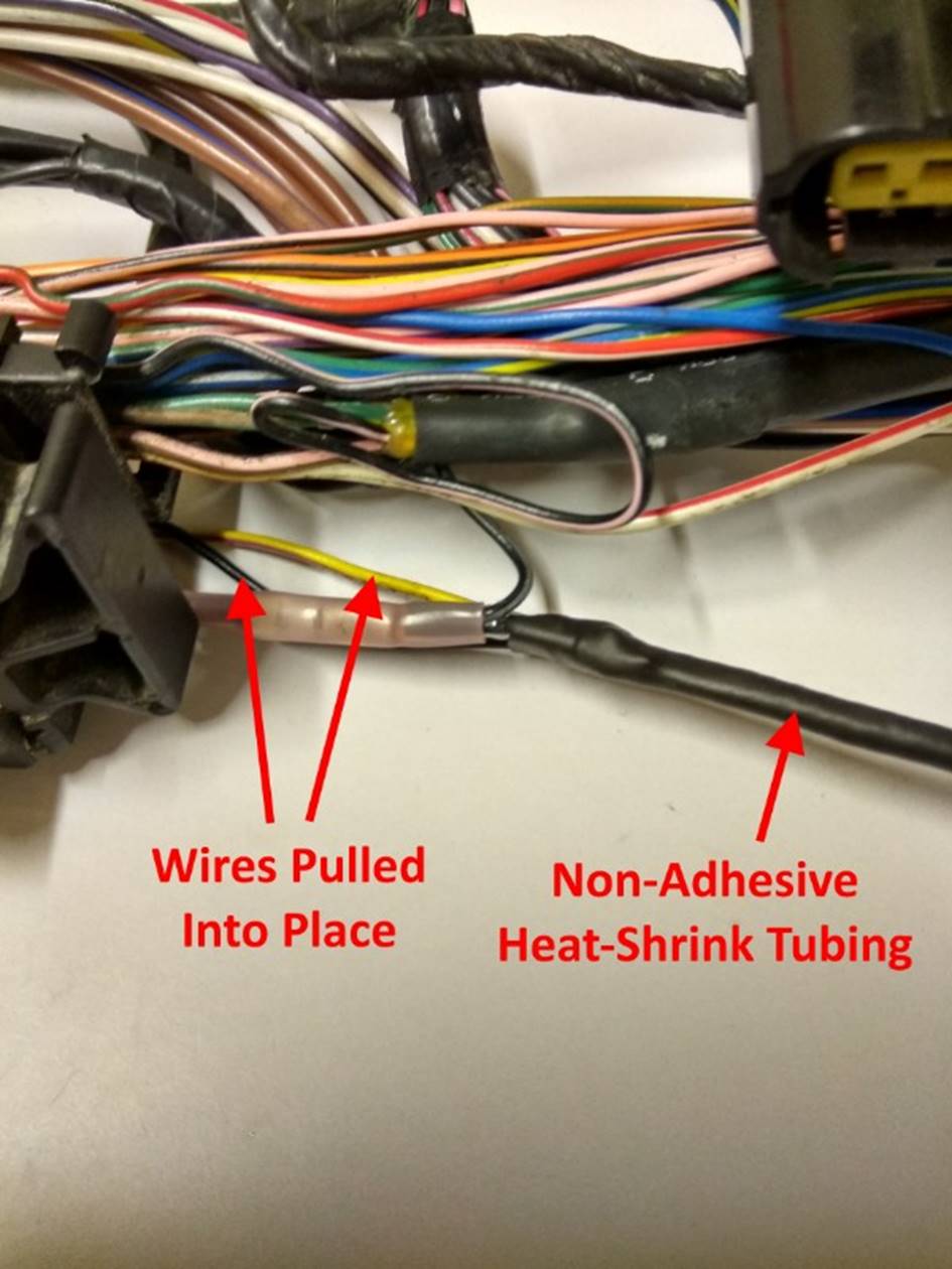
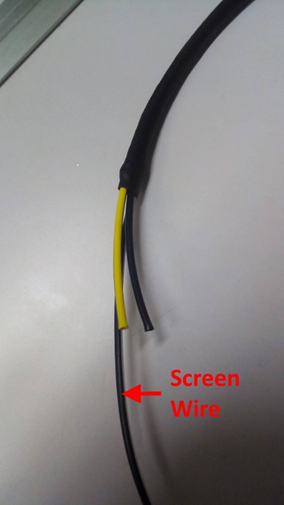
Once the crimped joint is complete, the signal wires can be pulled
through the braid taking up the slack, as shown in FIG 38. Heat-shrink tubing may be slipped over the screened braid
to form the outer insulator. This should completely cover the end of the screen
braid. Non-adhesive heat-shrink tubing should be used. If adhesive heat-shrink
tubing is used, the adhesive melts into the copper braid and the resulting
cable becomes rigid. With non-adhesive heat-shrink tuning, the cable remains
soft and flexible. At this stage it is easiest to only shrink the tubing along
around half its length working away from the ECU connector. This makes it a lot
easier to cut the heat-shrink, braid and signal wires back to required length
and to terminate the screen once routed through the loom.
FIG 38:
The new screened cable may now be routed neatly along the loom
away from the ECU connector and cable tied, as shown in FIG 39.
FIG 39:
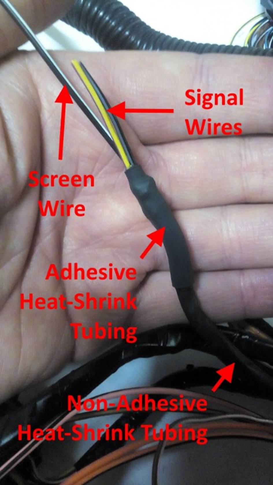
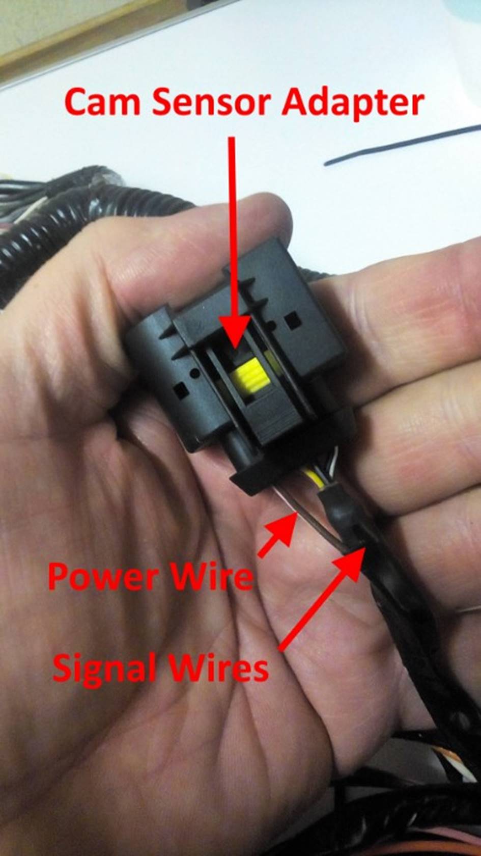
Once routed through the loom the cable may be brought out
alongside the MPi cam sensor power cable. The signal and power cables may then
be cut to a suitable length to allow the cam sensor adapter connector to be
installed (or to a suitable length to allow the VVC cam sensor connector to be
installed directly if the optional adapter connector and sub-loom are not being
used). If the optional adapter connector is being used to allow the loom to be
used with an MPi engine it will be necessary to extend the screen to the
sub-loom, so a Black/White wire should be soldered to the end of the screen
braid as at the other end of the cable. The braid should be cut back shorter
than the signal cables and the heat-shrink should be cut back shorter than the
braid. The braid should be splayed out away from the signal cables in order to
allow the screen connection to be soldered without damaging the insulation.
Once soldered, the remaining length of the heat-shrink can be shrunk into place
and short length of adhesive heat-shrink may be applied to insulate the exposed
braid and seal the end of the cable, as shown in FIG 40.
VVC-Only
Loom: Where there is no requirement to be able to use the
loom with an MPi engine, the signal cables may then be cut to a suitable length
to allow the VVC cam sensor connector to be installed directly. The steps
described in the notes for FIG 41
and FIG 44 would then be omitted.
Instead the cables would be terminated without a screen connection as show in FIG 45 and the VVC cam sensor connector
installed directly as shown in FIG 46.
FIG 40:
The optional adapter connector may then be fitted to the cut ends
of the signal, screen and power cables, as shown in FIG 41. A proper and
suitable F-type ratchet crimping tool and appropriate wire seals should be used
as before.
VVC-Only
Loom: Where there is no requirement to be able to use the
loom with an MPi engine, this step would be omitted.
FIG 41:
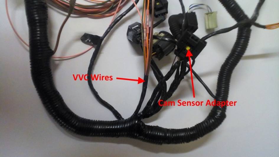
The unwrapped portions of the loom may now be taped up again and
any split convoluted tubing which was removed may be reinstalled and taped
over. The cables for the VVC solenoids and oil temperature sensor may be taped
as single bundle and the signal and power cables for the cam sensor may also be
taped as a bundle, as shown in FIG 42.
When taping bundles of cable branched off from the main loom, where possible it
is good to start from the free end and work back towards the main run of the
loom, ending in a turn or two around the main loom; in this way when the main
loom is taped up the free ends are taped down and the tape cannot unwind over
time. The back shell of ECU Connector 1 may be clipped back into place now. The
cables are normally cable tied to the connector housing as they exit for
security. Remember to click the two secondary locks back into the locked
position in order to securely lock all the terminals into place and allow the
connector to mate with the ECU.
FIG 42:
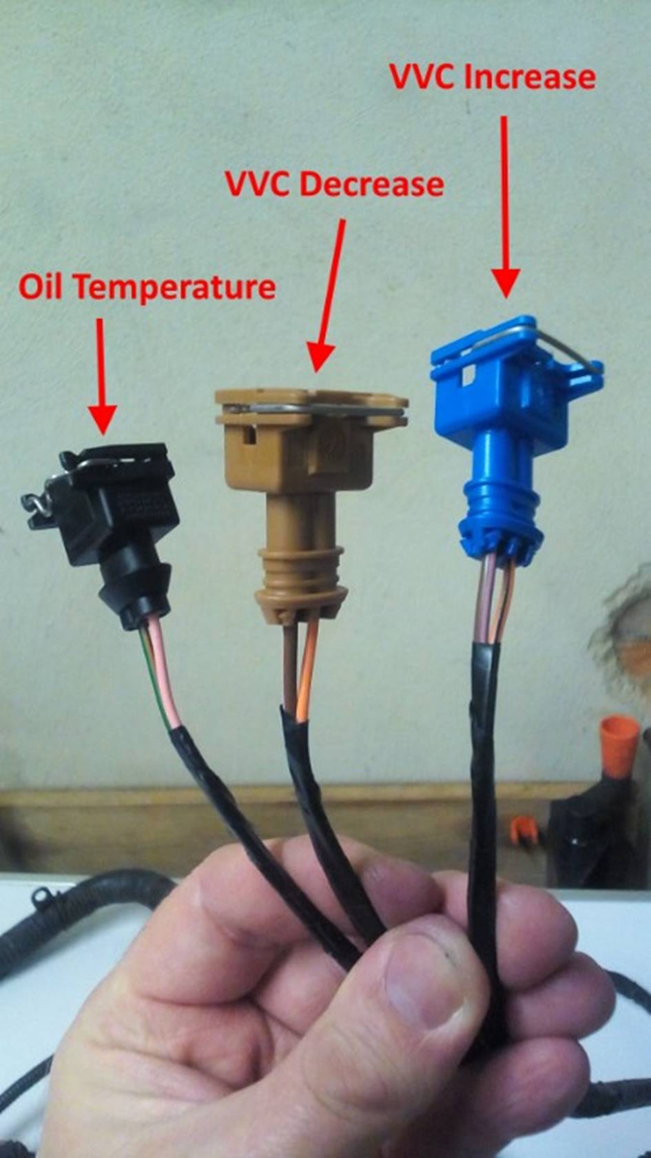
The bundle of cables for the VVC solenoids and oil temperature
sensor may now be divided into three branches for the three connectors for the
final 15cm or so of their length and then taped up. The three connectors are
then installed as shown in FIG 43. A
proper and suitable F-type ratchet crimping tool and appropriate wire seals
should be used as before. This completes the changes to the main loom.
FIG 43:
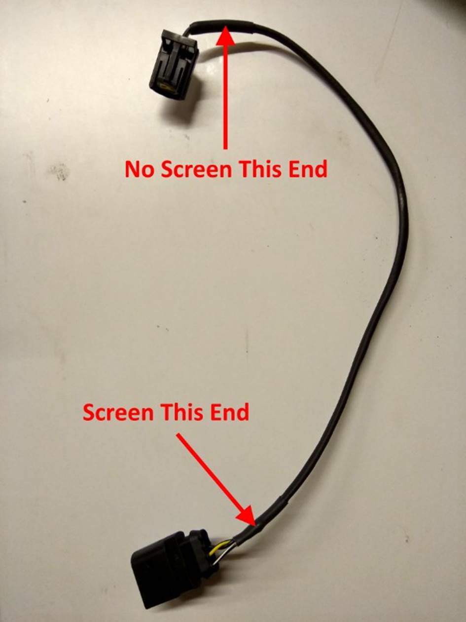
The sub-looms for the VVC and MPi cam sensors may now be made up.
For the VVC cam sensor sub-loom we again make this from screened cable, using
screen braid and heat shrink exactly as before. This time however, we only need
to solder on a Black/White wire at the end which connect to the adapter
connector, as shown in FIG 44. The
VVC sub-loom only connects to the signal and screen pins in the adapter
connector and does not use the power supply wire.
VVC-Only
Loom: Where there is no requirement to be able to use the
loom with an MPi engine, this step would be omitted.
FIG 44:
At the end which connects to the sensor connector, we simply use a
length of adhesive heat-shrink tubing to insulate and seal the cable, making
sure that the end of the screen brain is completely covered, as shown in FIG 45. It is important that the whole
screen is only connected at one end to prevent any currents flowing in the
screen inducing noise in the signal wires.
VVC-Only
Loom: Where there is no requirement to be able to use the
loom with an MPi engine, the ends of the extended cables for the VVC cam sensor
would be insulated in this way.
FIG 45:
Appropriate connectors are installed at each end of the sub-loom,
as shown in FIG 46. A proper and
suitable F-type ratchet crimping tool and appropriate wire seals should be used
as before.
VVC-Only
Loom: Where there is no requirement to be able to use the
loom with an MPi engine, the VVC cam sensor would be installed directly onto
the cables from the main loom.
FIG 46:
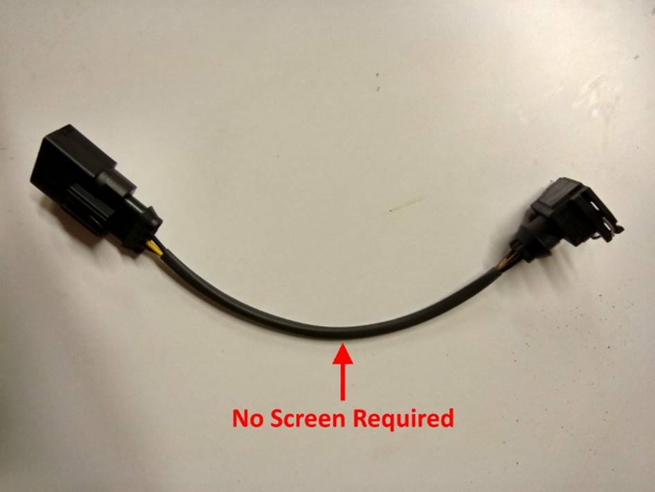
The MPi sub-loom only connects to the signal and power pins in the
adapter connector and does not need to be screened, as shown in FIG 47.
VVC-Only
Loom: Where there is no requirement to be able to use the
loom with an MPi engine, this step would be omitted.
FIG 47:
The loom changes are now complete. The loom may be used with a VVC
engine. If the optional adapter connector was installed, the loom may be used
again with an MPi engine simply by swapping the sub-looms. For an MPi engine
the additional VVC solenoid and oil temperature sensor connectors would be left
unused and tied neatly back against the loom somewhere convenient. The finished
VVC loom is shown in FIG 48.
FIG 48:
Installation
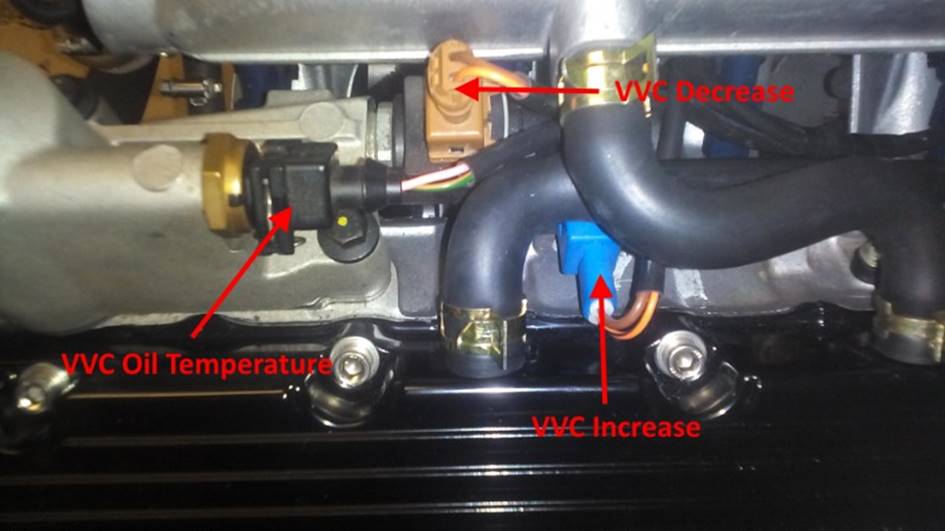
The additional VVC connectors are connected as show in FIG 49. Be warned that Rover changed
the colour coding of the VVC solenoids between EU2 and EU3 and pictures on the
Internet may show the blue and brown coloured plugs apparently installed the
other way around. The installation shown in FIG 49 is correct for an EU3 installation
and for a loom wired as described in this article.
FIG 49:
Connector
Pinouts
ECU Connector
1 Pin Layout
FIG 50:
Cam Sensor
Adapter Pin Layout
VVC-Only
Loom: Where there is no
requirement to be able to use the loom with an MPi engine, this connector would
be omitted.
FIG 51:
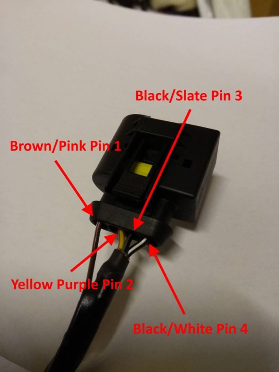
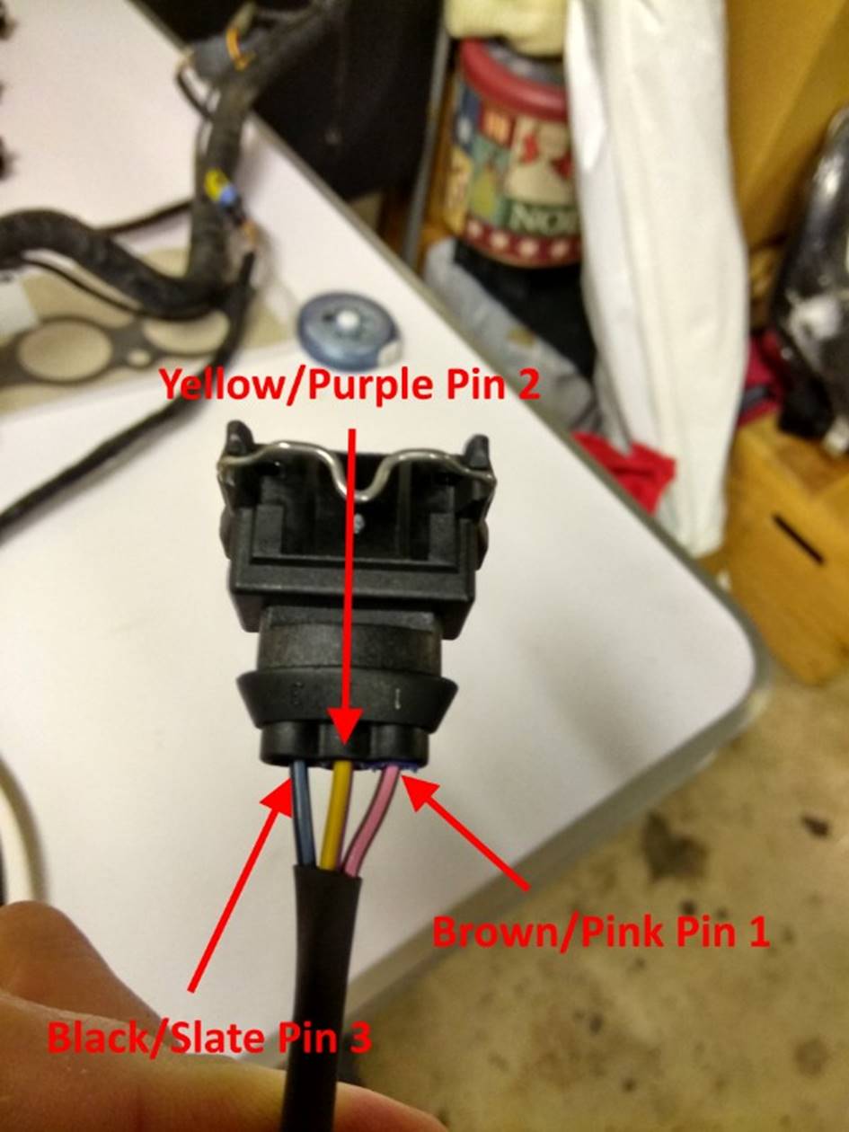
VVC Cam
Sensor Sub Loom Adapter End Pin Layout
VVC-Only
Loom: Where there is no
requirement to be able to use the loom with an MPi engine, this connector would
be omitted.
FIG 52:
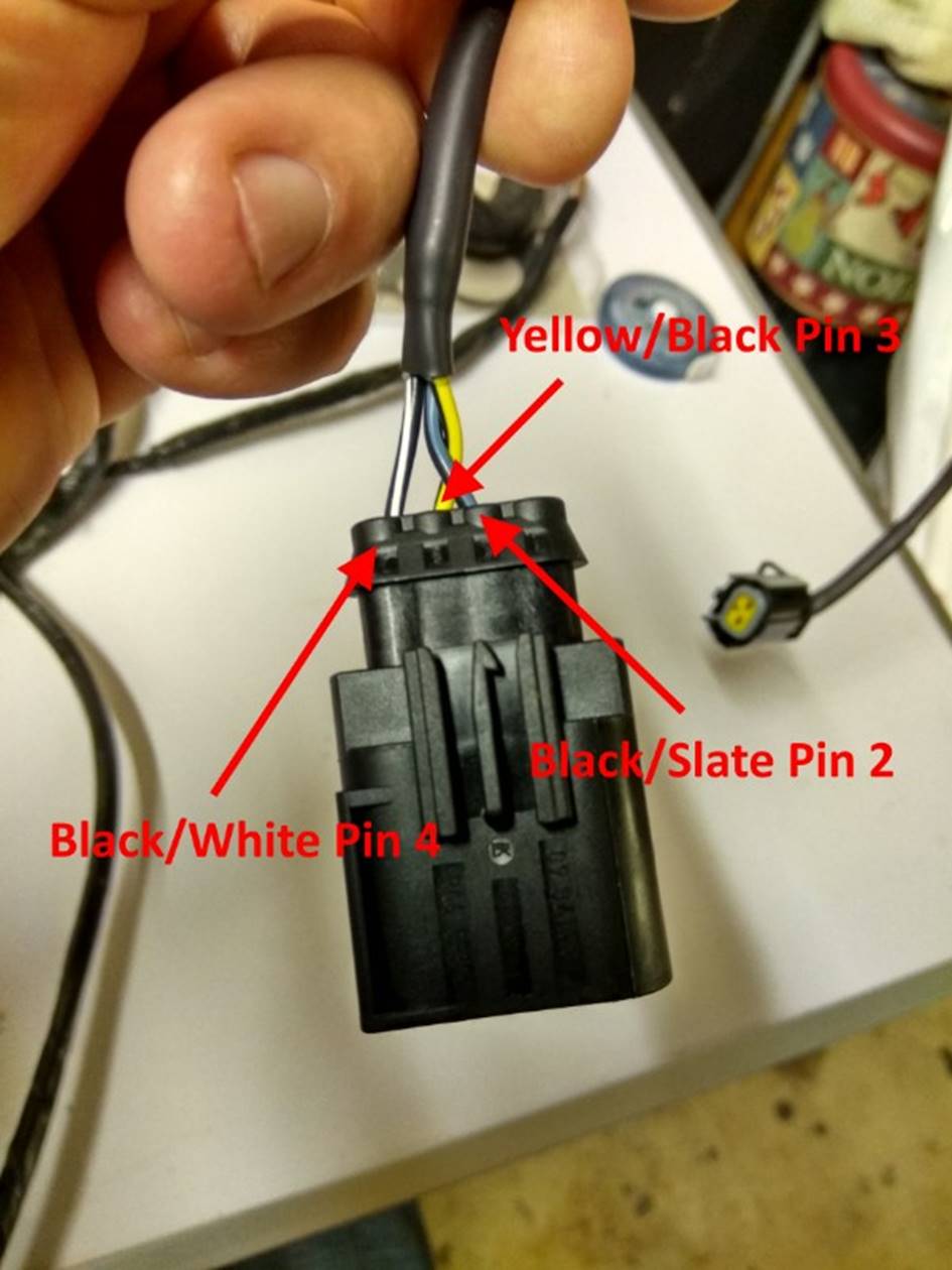
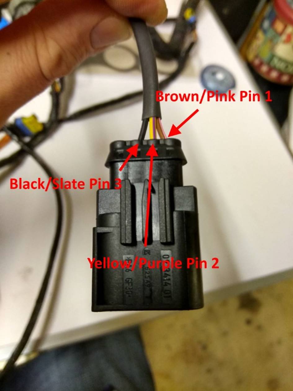
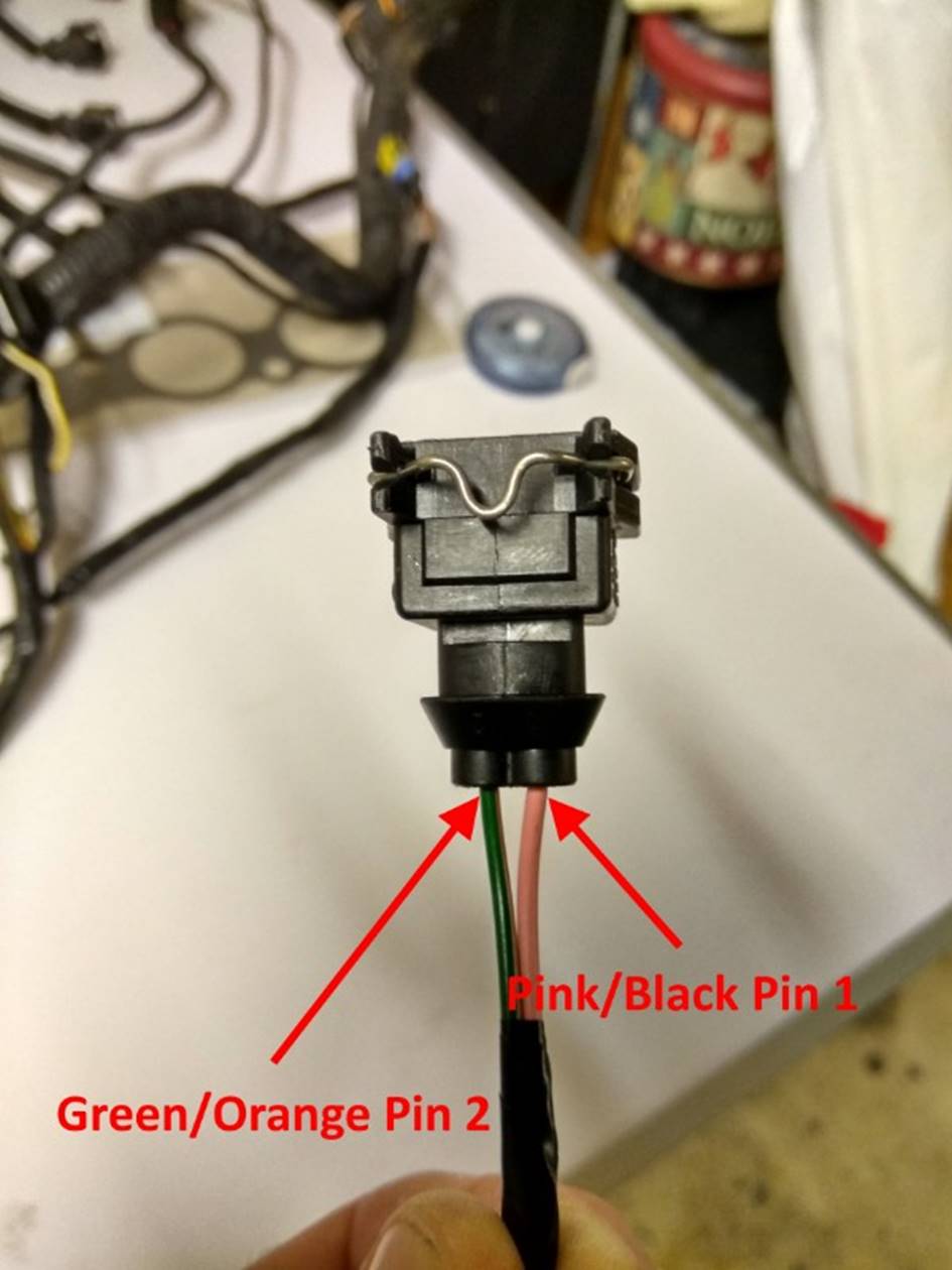
VVC Cam
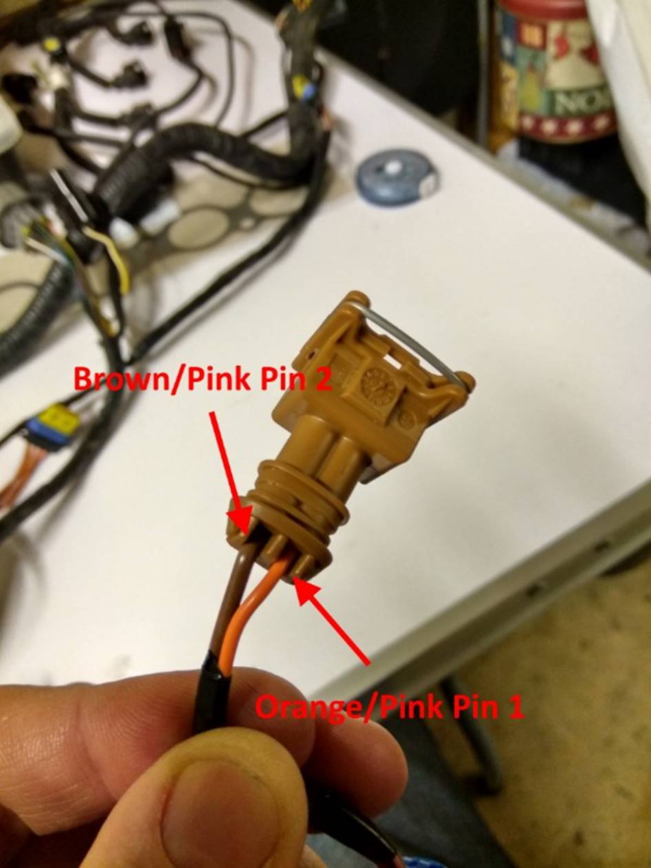
Sensor Sub Loom Sensor End Pin Layout
FIG 53:
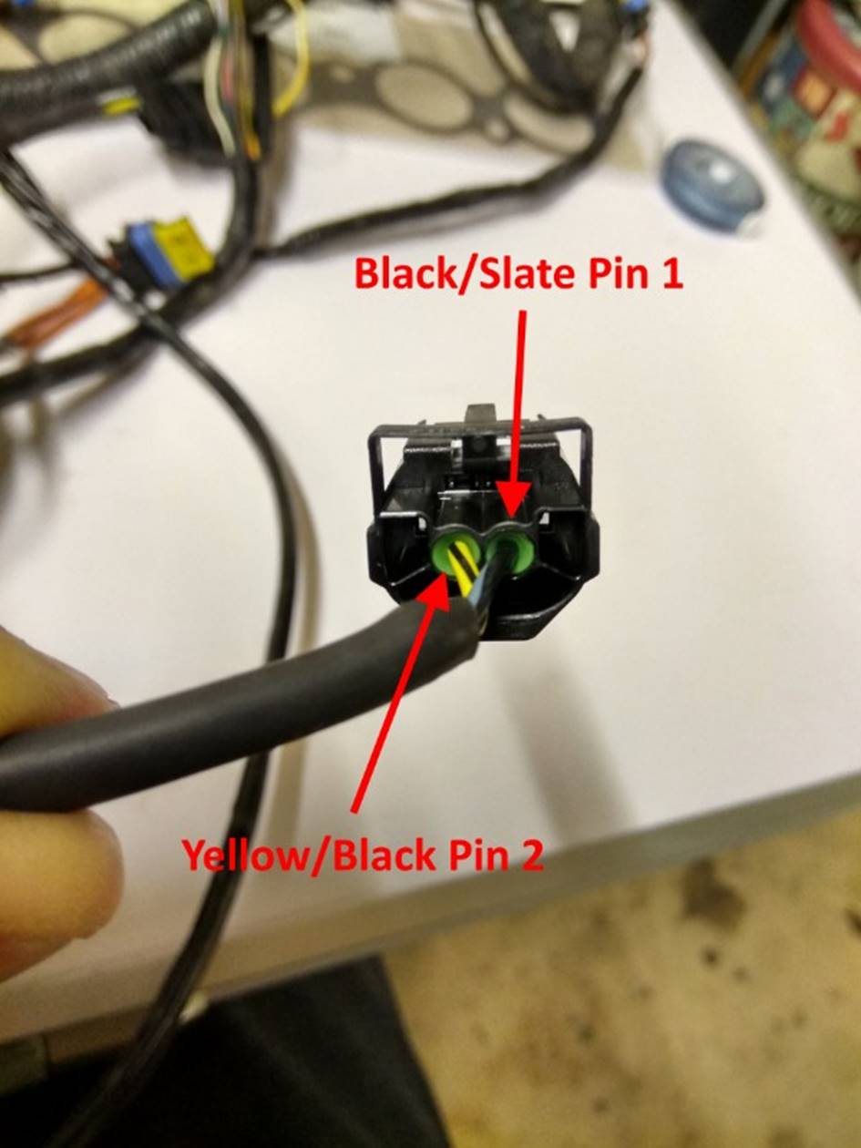
VVC Cam
Sensor Sub Loom Sensor End Pin Layout Alternate
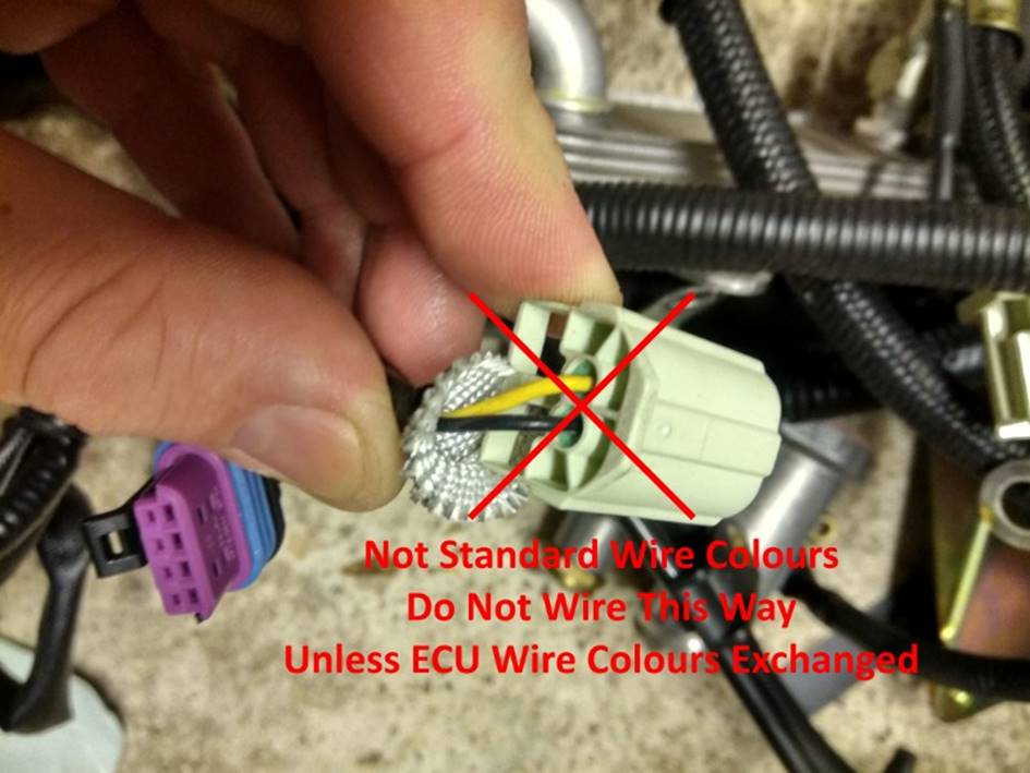
Warning: I have seen some Rover looms where the wire colours to
the VVC cam sensor connector are transposed, as in FIG 54. These looms have the wire colours transposed at both
connectors, so the same pins on the cam sensor still connect to the same pins
on the ECU. To further complicate matters, the K Series wiring diagram issued
by Caterham incorrectly shows these wires transposed at one end only,
connecting the sensor pins to the wrong ECU pins. If the cam sensor is wired
backwards in this way it will not work correctly. The negative feedback loop
used to control the VVC mechanism position effectively becomes a positive
feedback loop and the VVC mechanisms tend to lock hard against one end of their
travel or the other apparently at random after revving the engine. The wiring
in FIG 53 is correct if the rest of
the instructions in this article have been followed correctly.
FIG 54:
MPi Cam
Sensor Sub Loom Adapter End Pin Layout
VVC-Only
Loom: Where there is no
requirement to be able to use the loom with an MPi engine, this connector would
be omitted.
FIG 55:
MPi Cam
Sensor Sub Loom Sensor End Pin Layout
VVC-Only
Loom: Where there is no
requirement to be able to use the loom with an MPi engine, this connector would
be omitted.
VVC-Only
Loom: Where there is no
requirement to be able to use the loom with an MPi engine, this connector would
be omitted.
FIG 56:
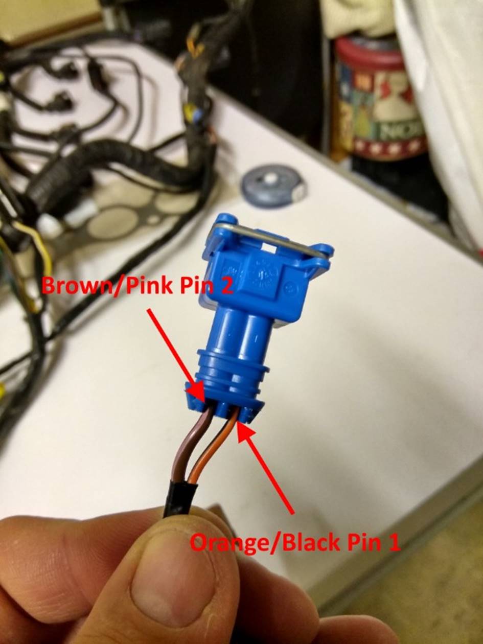
VVC Increase
Solenoid Pin Layout
FIG 57:
VVC Decrease
Solenoid Pin Layout
FIG 58:
VVC Oil
Temperature Sensor Pin Layout
FIG 59:
Parts List
|
|
||||||||||||||||||||||||||||||||||||||||||||||||||||||||||||||||||||||||||||||||||||||||||||||||||||||||||||||||||||||||||||||||||||||||||||||||||||||||||||||||||||||||||||||||||||||||||||||||||||||||||||||||||||||||||||||||||||||||||||||||||||||||||||||||||||||||||||||||||||||||||||||||||||||||||||||||||||||||||||||||||||||||||||||||||||||||||||||||||||||||||||||||||||||||||||||||||||||||||||||||||||||||||||||||||||